1
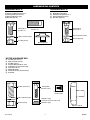
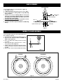
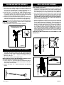
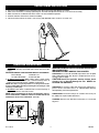
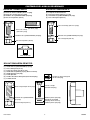
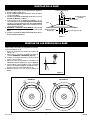
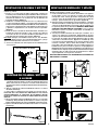
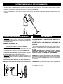
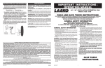
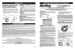
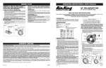
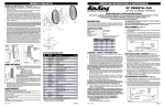
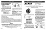
30" INDUSTRIAL GRADE OSCILLATING
PEDESTAL FAN WITH WHEELS
Model X30400
READ AND SAVE THESE INSTRUCTIONS
READ CAREFULLY BEFORE ATTEMPTING TO ASSEMBLE, INSTALL, OPERATE OR MAINTAIN THE PRODUCT DESCRIBED.
PROTECT YOURSELF AND OTHERS BY OBSERVING ALL SAFETY INFORMATION. FAILURE TO COMPLY WITH
INSTRUCTIONS COULD RESULT IN PERSONAL INJURY AND/OR PROPERTY DAMAGE!
RETAIN INSTRUCTIONS FOR FUTURE REFERENCE.
INCLUDED WITH THIS FAN:
(1)3 Speed, Oscillating Motor Assembly
(1) Column Assembly
(1)Base
(1)Blade
(1) Front Grill
(1) Rear Grill
(1) Hardware Bag
(1) Motor Hardware Bag
(1) Wheel Kit Bag
(1) Instruction Sheet
GENERAL SAFETY INFORMATION
11.NEVER operate any Fan with a damaged cord or plug or after
the Fan malfunctions, has been dropped or damaged in any
manner.
12.Do not insert or allow fingers or foreign objects to enter any
ventilation or exhaust opening as it may cause an electric shock
or fire, or damage the Fan. Do not block or tamper with the Fan
in any manner while it is in operation.
13.Always place the Fan on a stable, flat, level surface when
operating, to avoid the chance of the Fan overturning. Locate
the Power Cord so the Fan or other objects are not resting on it.
Do not run cord under carpeting. Do not cover cord with throw
rugs, runners, or similar coverings. Do not route cord under
furniture or appliances. Arrange cord away from traffic area and
where it will not be tripped over.
14.This Fan is not intended for use in wet or damp locations.
Never locate a Fan where it may fall into a bathtub or other
water container.
15. Do not use Fan outdoors.
16.This Fan is not suitable for use in agricultural facilities including
areas where livestock, poultry or other animals are confined.
Please refer to National Electric Code (NEC) Article 547-7
(2008), or applicable state or local codes or standards relating
to electrical requirements for Agricultural Buildings. THIS FAN
DOES NOT MEET THE REQUIREMENTS OF NEC ARTICLE
547-7 (2008).
17.This Fan is not suitable for use in hazardous locations. Please
refer to National Electric Code (NEC) Article 500 or applicable
state or local codes or standards relating to electrical
requirements for Hazardous locations. THIS FAN DOES NOT
MEET THE REQUIREMENTS OF NEC ARTICLE 500 (2008).
WARNING: REDUCE THE RISK OF FIRE OR ELECTRIC SHOCK
– DO NOT USE THIS FAN WITH ANY SOLID STATE SPEED
CONTROL DEVICES.
CAUTION: BECAUSE OF THE SIZE AND WEIGHT OF THIS
FAN, MAKE SURE ALL PARTS ARE COMPLETELY ASSEMBLED
ACCORDING TO INSTRUCTIONS. FAILURE TO DO SO COULD
RESULT IN FAN COMING APART DURING OPERATION AND/OR
PERSONAL INJURY.
1. Read all instructions before using Fan. 2. Make certain that the power source conforms to the electrical requirements of the Fan.
3. Use this Fan only as described in this manual. Any other use not
recommended by the manufacturer may cause fire, electrical
shock, or injury to persons.
4. To reduce the risk of personal injury and electric shock, the
Fan should not be played with or placed where small children
can reach it.
5. Unplug power cord before servicing, or moving the Fan.
WARNING: DO NOT DEPEND UPON THE ON-OFF SWITCH
AS THE SOLE MEANS OF DISCONNECTING POWER WHEN
INSTALLING OR SERVICING THE FAN. ALWAYS UNPLUG THE
POWER CORD.
6. This Fan must NOT be used in potentially dangerous
locations such as flammable, explosive, chemical-laden
or wet atmospheres.
7. DO NOT use Fan in or near a window. Rain may create an
electrical hazard.
8. Completely reassemble Fan, according to instructions,
before reconnecting to power supply.
9. The power cord is equipped with a three-prong grounded
plug that must be inserted into a matching receptacle. Under
no circumstances should the grounding prong be cut off the
plug. Where a two-prong wall receptacle is encountered,
it must be replaced with a properly grounded three-prong
receptacle installed in accordance with the National Electrical
Code (NEC) and all applicable local codes and ordinances.
This work must be done only by a qualified electrician, using
copper wire only.
WARNING: USE OF A THREE-PRONG TO TWO-PRONG
ADAPTER IS NOT RECOMMENDED. IMPROPER CONNECTION
MAY CREATE THE RISK OF ELECTROCUTION. USE OF SUCH
ADAPTER IS NOT PERMITTED IN CANADA.
10. Where possible, avoid the use of extension cords. If they must
be used, minimize the risk of overheating by ensuring that they
are UL listed. Never use a single extension cord to operate
more than one Fan.
Rev. A 10/11
Register Your Product Today
www.laskoproducts.com/registration
You will benefit from:
- efficient and enhanced support
- future product updates
scan with a smart phone
SAVE THESE INSTRUCTIONS
1
5084440
HARDWARE BAG CONTENTS
HARDWARE BAG D:
HARDWARE BAG A:
(1) (1)
(4)
(4)
(4)
(1) Mounting Flange
(1) Square Head Bolt (3/8-16 X 1”)
(4) Carriage Bolts (3/8-16 X 1”)
(4) Split Lockwashers (3/8”)
(4) Hex Nuts (3/8-16)
Carriage Bolt
(3/8-16 X 1”)
Left Wheel Assembly
Right Wheel Assembly
Carriage Bolts (5/16-18 X 1”)
Split Lockwashers (5/16”)
Hex Nuts (5/16-18)
Square Head Bolt
(3/8-16 X 1”)
Carriage Bolt
(5/16-18 X 1”)
Split Lockwasher (5/16”)
Split Lockwasher (3/8”)
Hex Nut (5/16-18)
Hex Nut (3/8-16)
Mounting Flange
MOTOR HARDWARE BAG
(1)
(1)
(1)
(1)
(1)
(2)
(1)
(6)
(1)
Hex Bolt (1/2-13 X 1”)
Split Lockwasher (1/2”)
Hex Nut (1/2-13)
Carriage Bolt (1/4-20 X 1 5/8”)
Lockwasher (1/4” Internal Tooth)
Flatwashers (1/4”)
Adjustable Knob
Hex Head Screws (10-32 X 5/16”)
Pull Cord
Hex Bolt (1/2-13 X 1”)
Carriage Bolt
(1/4-20 X 1 5/8”)
Hex Head Screws
(10-32 X 5/16”)
Split Lockwasher (1/2”)
Hex Nut (1/2-13)
Flatwasher (1/4”)
Lockwasher (1/4” Internal Tooth)
Flatwasher (1/4”)
Adjustment Knob
Rev. A 10/11
2
5084440
BASE ASSEMBLY
Carriage Bolts (4)
Locate Hardware Bag “A” to Assemble Base. (Figure 1)
1. Place Base on floor.
2.Fit Mounting Flange through large hole in center of Base.
3. Insert (4) 3/8-16 X 1” Carriage Bolts through Mounting
Flange and Base.
4.Tilt Base and secure one Carriage Bolt at a time by first
putting on a 3/8” Split Lockwasher and then a 3/8-16 Hex
Nut. DO NOT FULLY TIGHTEN AT THIS TIME. Repeat above
procedure with remaining Bolts.
5. GO BACK AND FULLY TIGHTEN each Hex Nut so that the
Flange is securely assembled to the Base.
6. Thread the 3/8-16 X 1” Square Head Bolt into the Mounting
Flange.
Square Head
Bolt
Mounting Flange
Base
Split Lockwasher (4)
Hex Nut (4)
Figure 1
WHEELS TO BASE ASSEMBLY
Locate Hardware Bag “D” to Assemble Wheels to
Base. (Figures 2 and 3)
1. Remove Wheel Assemblies from Hardware Bag “D”.
2. Take note that Wheel Assemblies are RIGHT and
LEFT handed. (Figure 3)
3. Place one Wheel Assembly on Base location
as shown.
4. Align two bolt holes and insert 5/16 - 18 X 1”
Long Carriage Bolt. (Figure 2)
5. Tilt Base and Secure one bolt at a time by first putting on a 5/16 Split Lockwasher and then a 5/16-18
Hex Nut.
6. Repeat steps 2 thru 5 with other Wheel Assembly.
Figure 2
CORRECT
INCORRECT
Figure 3
Rev. A 10/11
3
5084440
COLUMN AND MOTOR ASSEMBLY
GRILL AND BLADE ASSEMBLY
Locate Motor Hardware Bag to Assemble Column and Motor Assembly.
1. Place flat section on Upper Tube of Column Assembly next to
Neck on Motor Assembly. Align the 1/2” diameter hole in the
flat section on the Upper Tube of Column Assembly with the
1/2” diameter hole in the Motor Assembly. (Figure 4)
2. Insert the 1/2” X 1” Hex Bolt (3/4” head) through the Motor
Neck, and the Upper Tube Assembly. Place 1/2” diameter Split
Lockwasher then the 1/2” diameter Hex Nut (3/4” head) and
tighten fully with a adjustable wrench. (Figure 4)
3. From the same side of the Motor Neck,insert one 1/4-20 X 1 5/8”
Carriage Bolt through the Arc-Shaped Slot in the Motor Neck
and Hole in the Upper Pipe of Column Assembly. (Figure 4)
To Fasten: Place one 1/4” Flatwasher, one 1/4” Internal Tooth Lockwasher, a second 1/4” Flatwasher and then tighten the Adjustable
Knob over the remaining threads.
4. Attach pull string to motor speed switch, if desired.
Locate remaining parts from Motor Hardware Bag to Assemble
Grills and Blade to the Motor.
1. Install the Rear Grill onto the Motor, lining up the six holes in the
grill with the six threaded holes in the motor mounting flange.
Install (6) 10-32 X 5/16” Hex Screws through the rear grill into
the mounting flange. Securely tighten all (6) screws. (Figure 6)
2. Push the Fan Blade onto the Motor Shaft, centering the Hub
facing away from the motor, until it stops against the shaft
(Inset A) . Align Square Head Bolt with flat of the motor shaft.
TIGHTEN VERY SECURELY WITH AN ADJUSTABLE WRENCH.
Failure to securely tighten the Bolt could result in damage to
the Fan and/or personal injury.
3. Hold the Front Grill so that the name, in the center, is right side
up and straight across. Starting at the top: Fasten Front Grill
to Rear Grill by sliding the hooked wires on the Front Grill over
the outermost ring on the Rear Grill. (Figure 7 / Detail A). The
bottom most hooks will require the use of a flathead screwdriver
to complete assembly. Stand behind the Fan. Slip the flat of
the screwdriver between the Front and Rear Grills, next to one
of the unfastened hooks. (Figure 7 / Detail B) Pull screwdriver
handle upwards towards the Rear Grill. Slip the Front Grill hook
over the Rear Grill outer ring with a push. Repeat procedure
with remaining hooks.
CAUTION: DO NOT BEND WIRES ON THE FRONT OR THE
REAR GRILLS.
Actual motor not shown for
detailed hardware view.
Figure 4
Inset A
COLUMN/MOTOR TO BASE ASSEMBLY
1. Rest Column and Motor Assembly on floor next to the Base
Assembly. Tilt Base Assembly up on end. Pick up lower pipe
of Column Assembly and insert into the Mounting Flange. (Figure 5)
2.Tighten the 3/8-16 X 1” Square Head Bolt into the
Mounting Flange.
3. Tilt entire assembly to the upright position.
MAKE SURE BOLTS IN COLUMN AND MOTOR ASSEMBLY STEPS
ARE TIGHT BEFORE STANDING FAN UPRIGHT.
4. Loosen 3/8-16 X 1” Square Heat Bolt in the Mounting Flange.
This will allow the Column to settle in the bottom of the Base
after setting the Fan upright.
5. Tighten the 3/8-16 X 1” Square Head Bolt in the Mounting
Flange.
Figure 6
Detail A
Figure 7
Detail B
Figure 5
Rev. A 10/11
4
5084440
REPOSITIONING INSTRUCTIONS
1.
2.
3.
4.
5.
Disconnect ALL POWER before repositioning Fan. Never move Fan while blade is in motion.
Make sure Fan Head is secured by tightening 1/2” Hex Bolt and adjustment knob to secure the head assembly.
Make sure that the oscillation knob in the motor is in the locked down position.
Position and lower Fan head as shown for stability.
Tilt fan back onto wheels as shown. Fan is heavy and awkward; make certain to use extra care.
OPERATING INSTRUCTIONS
MAINTENANCE
1. To Operate: Plug cord into a grounded 120V, 60 Hz outlet. Select desired operating speed with pull cord on the rear of the
motor.
CAUTION: FAN MAY START UP WHEN INITIALLY PLUGGED IN.
First Pull:High
Third Pull: Low
Second Pull: Medium
Fourth Pull: OFF
2. To Adjust Head Height: While holding upper column firmly,
loosen bolt on column collar (turn counterclockwise). Raise or
lower head to desired position. FIRMLY retighten bolt.
NOTE: This Fan is very heavy. Failure to securely hold onto the
head assembly while adjusting head height or head angle could
result in personal injury.
3. Oscillation: Push down oscillation knob on motor housing to
make fan head move from side to side.
NOTE: FAN IS SHIPPED WITH 90º OSCILLATION ANGLE, FOR 45º
OSCILLATION ANGLE, CONNECT THE OSCILLATION LINK TO THE
INNERMOST HOLE IN THE CAM GEAR. (Inset A)
WARNING: ALWAYS UNPLUG THE CORD BEFORE MOVING OR SERVICING.
WARNING: DO NOT IMMERSE FAN IN WATER!
CLEANING: Use a soft cloth and mild soap solution such as liquid
dish washing detergent. Dry all parts completely before reconnecting to power supply.
CAUTION: Do not use gasoline, benzine, thinner, harsh
cleaners, etc. as they will damage the Fan. NEVER use
ALCOHOL OR SOLVENTS.
SERVICING: For servicing, other than general user maintenance,
please contact Customer Service at 800-233-0268, Monday
through Friday, from 8am-5pm Eastern.
LUBRICATION: Precision bearings are sealed at the factory for
life and do not require further lubrication.
STORAGE: Store the Fan, with these instructions, in a clean and
dry place.
45˚ 90˚
3.
Cam Gear
(Inset A)
1.
2.
Rev. A 10/11
5
5084440
 LASKO PRODUCTS, INC. LIMITED WARRANTY(Valid in the USA, its Territories, and CANADA Only)
WHAT THIS WARRANTY COVERS:  This product is warranted against defects in workmanship and/or materials.
HOW LONG THIS WARRANTY LASTS:  This warranty extends only to the original purchaser of the product and lasts for one (1) year from the date
of original purchase or until the original purchaser of the product sells or transfers the product, whichever first occurs.
WHAT LASKO WILL DO:  During the warranty period, Lasko will, at its sole option, repair or replace any part or parts that prove to be defective
or replace the whole product with the same or comparable model.
WHAT THIS WARRANTY DOES NOT COVER:  This warranty does not apply if the product was damaged or failed because of accident, improper
handling or operation, shipping damage, abuse, misuse, unauthorized repairs made or attempted.This warranty does not cover shipping costs
for the return of products to Lasko for repair or replacement.  Lasko will pay return shipping charges from Lasko following warranty repairs or
replacement.
ANY AND ALL WARRANTIES, EXPRESSED OR IMPLIED (INCLUDING, WITHOUT LIMITATION, ANY IMPLIED WARRANTY OF
MERCHANTABILITY), LAST ONE YEAR FROM THE DATE OF ORIGINAL PURCHASE OR UNTIL THE ORIGINAL PURCHASER OF THE
PRODUCT SELLS OR TRANSFERS THE PRODUCT, WHICHEVER FIRST OCCURS AND IN NO EVENT SHALL LASKO’S LIABILITY UNDER
ANY EXPRESS OR IMPLIED WARRANTY INCLUDE (I) INCIDENTAL OR CONSEQUENTIAL DAMAGES FROM ANY CAUSE WHATSOEVER, OR
(II) REPLACMENT OR REPAIR OF ANY HOUSE FUSES, CIRCUIT BREAKERS OR RECEPTACLES.  NOTWITHSTANDING ANYTHING TO THE
CONTRARY, IN NO EVENT SHALL LASKO’S LIABILITY UNDER ANY EXPRESS OR IMPLIED WARRANTY EXCEED THE PURCHASE PRICE OF
THE PRODUCT AND ANY SUCH LIABILITY SHALL TERMINATE UPON THE EXPIRATION OF THE WARRANTY PERIOD.
Some states and provinces do not allow limitations on how long an implied warranty lasts, or the exclusion or limitation of incidental or consequential
damages, so these exclusions or limitations may not apply to you.  This warranty gives you specific legal rights. You may also have other rights
which vary from state to state and province to province.
Proof of purchase is required before a warranty claim will be accepted.
CUSTOMER SERVICE:
Toll-Free (800) 233-0268. Email: [email protected]
Our Customer Service team is available to assist you with product and service questions, and replacement parts.
They can be reached Monday through Friday, 8am-5pm Eastern. Please have your model number available, as
well as the type and style (located on the underside of your product).
Customer Service Dept., 820 Lincoln Ave., West Chester, PA 19380
(Please do not send product to this location) www.laskoproducts.com
Rev. A 10/11
6
5084440
Ventilador Oscilante de Pedestal
de 30” con Ruedas, para Uso
Industrial
Modelo X30400
LEA Y GUARDE ESTAS INSTRUCCIONES
LEA CUIDADOSAMENTE LAS INSTRUCCIONES ANTES DE INTENTAR ARMAR, INSTALAR, USAR O DAR
MANTENIMIENTO AL PRODUCTO DESCRITO.
PROTÉJASE A SÍ MISMO Y A LOS DEMÁS CUMPLIENDO CON TODA LA INFORMACIÓN DE SEGURIDAD. EL NO
SEGUIR LAS INSTRUCCIONES PODRÍA RESULTAR EN LESIONES PERSONALES Y/O DAÑOS A LA PROPIEDAD.
CONSERVE LAS INSTRUCCIONES COMO FUTURA REFERENCIA.
INCLUIDO CON EL VENTILADOR:
(1) Conjunto de motor oscilante de 3 velocidades
(1) Conjunto de columna
(1)Base
(1)Hélice
(1) Parrilla delantera
(1) Parrilla trasera
(1) Bolsa de tornillería
(1) Motor bolsa tornillería
(1) Bolsa de juego de ruedas
(1) Hoja de instrucciones
12.No introduzca ni permita que se introduzcan dedos u objetos
INFORMACIÓN GENERAL SOBRE SEGURIDAD
extraños en ninguna abertura de ventilación o escape, puesto
1. Lea todas las instrucciones antes de utilizar el Ventilador.
que podría provocar un golpe de electricidad, incendio, o daños
2. Cerciórese de que la fuente de poder sea compatible con las
al ventilador. No bloquee ni manipule el Ventilador de ninguna
demandas eléctricas del Ventilador.
manera mientras esté en funcionamiento.
3. Use este Ventilador sólo en la forma que se describe en el
13.Siempre
coloque el Ventilador sobre una superficie, estable,
manual. Cualquier otro uso no recomendado por el fabricante
plana y horizontal mientras esté en funcionamiento, para evitar
podría ocasionar un incendio, golpes de electricidad o lesiones a
la posibilidad de que el Ventilador se dé vuelta. Ubique el cable
personas.
eléctrico de tal modo que el ventilador u otros objetos no
4. Para disminuir el riesgo de lesiones físicas y golpes de
descansen sobre él. No coloque el cable de corriente debajo de
electricidad, no debe jugarse con el ventilador no deberá éste
alfombras. No cubra el cable de corriente con tapetes, alfombras
ser ubicado al alcance de los niños pequeños.
estrechas o artículos de coberturas similares. No coloque el
5. Desenchufe el cable eléctrico antes de instalar, proporcionar
cable de corriente debajo de muebles o artefactos. Coloque el
servicio o mover el Ventilador.
cable de corriente lejos del tráfico de la habitación, donde las
ADVERTENCIA: NO DEPENDA DEL INTERRUPTOR DE ENCENDIDOpersonas no se tropiecen con éste.
APAGADO COMO EL ÚNICO MEDIO PARA DESCONECTAR LA POTENCIA
AL INSTALAR O PROPORCIONARLE SERVICIO AL VENTILADOR. 14.Este Ventilador no ha sido diseñado para usarse en lugares
mojados o húmedos. Nunca coloque un Ventilador donde quepa
DESENCHUFE SIEMPRE EL CABLE ELÉCTRICO.
la posibilidad de que caiga en una bañera u otro recipiente con agua.
6. Este Ventilador NO debe usarse en ubicaciones potencialmente
peligrosas, tales como en ambientes inflamables, explosivos, 15.No use el Ventilador en exteriores.
16.Este Ventilador no es adecuado para usar en instalaciones
cargados de sustancias químicas o húmedos.
de agricultura incluyendo áreas donde se almacene ganado,
7. NO use el ventilador ante una ventana, pues la lluvia podría
aves de corral u otros animales. Por favor consulte el Articulo
presentar riesgos eléctricos.
547-7 (2008) del Código Eléctrico Nacional (NEC), o los códigos
8. Vuelva a armar el ventilador por completo, siguiendo las
o normas estatales o locales aplicables con relación a los
instrucciones, antes de reconectarse a la fuente de poder.
requisitos eléctricos para edificios destinados a las agricultura.
9. El cordón eléctrico está equipado con una clavija a tierra de
ESTE VENTILADOR NO CUMPLE CON LOS REQUISITOS DEL
tres espigas que tiene que ser enchufada a un receptáculo del
ARTICULO 547-7 DEL NEC (2008).
mismo diseño. Bajo ninguna circunstancia deberá cortarse la
espiga a tierra de la clavija. De existir un receptáculo de pared 17. Este Ventilador no es adecuado para usar en lugares peligrosos.
Por favor consulte el Artículo 500 del Código Eléctrico Nacional
de dos espigas, deberá reemplazarse por uno de tres espigas
(NEC), o los códigos o normas estatales o locales aplicables
debidamente puesto a tierra e instalado de conformidad con
con relación a los requisitos eléctricos para lugares peligrosos.
el Código Nacional de Electricidad y todos los códigos y
ESTE VENTILADOR NO CUMPLE CON LOS REQUISITOS DEL
ordenanzas locales aplicables. El trabajo deberá hacerlo un
ARTICULO 500 (2008).
electricista calificado, utilizando exclusivamente alambre de cobre.
ADVERTENCIA: NO SE RECOMIENDA EL USO DE UN ADAPTADOR DE
TRES A DOS ESPIGAS. LA CONEXIÓN INDEBIDA PODRÍA CREAR EL
RIESGO DE SER ELECTROCUTADO. EL USO DE TALES ADAPTADORES
NO ESTÁ PERMITIDO EN CANADÁ.
10.De ser posible, evite el uso de cables de extensión. Si debieran
usarse, minimice el riesgo de sobrecalentamiento procurando
que estén aprobados por UL. Nunca use un solo cable de
extensión para hacer funcionar más de un Ventilador.
11.No haga funcionar ningún Ventilador con un cable o enchufe
dañado o después de que el ventilador presente algún
desperfecto o haya sido dejado caer o sufriera cualquier tipo
de daño.
Rev. A 10/11
7
ADVERTENCIA: DISMINUYA EL RIESGO DE INCENDIO O GOLPES DE
ELECTRICIDAD – NO USE ESTE VENTILADOR CON ARTEFACTOS DE
CONTROL DE VELOCIDAD EN ESTADO SÓLIDO.
Precaucion: Debido al tamano y peso de este Ventilador,
asegurese de que todas las piezas estan COMPLETAMENTE
MONTADAS DE ACUERDO CON LAS INSTRUCCIONES. Un fallo podria
causar la desunion de las piezas durante su funcionamiento
y/o danos personales.
CONSERVE ESTAS
INSTRUCCIONES
5084440
CONTENIDO DE LA BOLSA DE HERRAJES
BOLSA DE TORNILLERÍA A:
BOLSA DE TORNILLERÍA D:
(1) Brida de montaje
(1) Perno de cabeza cuadrada (3/8-16 x 1 pulg)
(4) Pernos de carruaje (3/8-16 x 1 pulg)
(4) Arandelas de seguridad divididas (3/8 pulg)
(4) Tuercas hexagonales (3/8-16)
(1) (1)
(4)
(4)
(4)
Conjunto de Rueda Izquierda
Conjunto de Rueda Derecha
Perno de Carruaje (5/16-18 x 1 pulg)
Arandela de Seguridad Dividida (5/16 pulg)
Tuerca Hexagonal (5/16-18)
Perno de Carruaje (5/16-18 x 1 pulg)
Perno de cabeza cuadrada
(3/8-16 X 1 pulg)
Pernos de carruaje
(3/8-16 X 1” pulg)
Arandela de Seguridad Dividida (5/16 pulg)
Arandelas de seguridad divididasr (3/8 pulg)
Tuerca hexagonal (5/16-18)
Tuercas hexagonales (3/8-16)
Brida de Montaje
bolsa tornillería DE Motor
(1) Perno Hexagonal (1/2-13 X 1 pulg)
(1) Arandela de Seguridad Dividida (1/2 pulg)
(1) Tuerca Hexagonal (1/2-13)
(1) Perno de Carruaje (1/4-20 X 1 5/8)
(1) Arandela de Seguridad (1/4 pulg, dientes internos)
(2) Arandela planas (1/4 pulg)
(1) Perilla Ajustable
(6) Tornillos de Cabeza Hexagonal (10-32 X 5/16 pulg)
(1) Cordón de Tirar
Tornillos de cabeza hexagonal
(10-32 x 5/16 pulg)
Perno hexagonal (1/2-13 X 1 pulg)
Perno de carruaje
(1/4-20 X 1 5/8 pulg)
Arandela de seguridad dividida
(1/2 pulg)
Arandelas planas (1/4 pulg)
Tuerca hexagonal (1/2- 13)
Arandela de Seguridad
(1/4 pulg, dientes internos)
Arandelas planas (1/4 pulg)
Perilla Ajustable
Rev. A 10/11
8
5084440
MONTAJE DE LA BASE
Ubique la Bolsa de Herrajes “A” para Montar la Base. (Figura 1)
1. Coloque la Base sobre el piso.
2. Encaje el Patín de Montaje a través del orificio grande en
el centro de la Base.
3. Introduzca (4) Tornillos de Carruaje de 3/8-16 X 1” a través
del Patín de Montaje y la Base.
4. Incline la Base y fije un Tornillo de Carruaje a la vez,
colocando primero una Arandela Fijadora Hendida de 3/8”
y después una Tuerca Hexagonal de 3/8-16. NO APRIETE
TOTALMENTE TODAVÍA. Repita el procedimiento anterior
con los Tornillos restantes.
5. REGRESE Y APRIETE TOTALMENTE cada Tuerca
Hexagonal de modo que el Patín esté fijo con firmeza a la
Base.
6. Introduzca el Tornillo de Cabeza Cuadrada de 3/8-16 X 1”
dentro del Patín de Montaje.
Tornillo De Carruaje (4)
Tornillo De Cabeza
Cuadrada
Patín De Montaje
Base
Arandelas Figadora
Hendida (4)
Tuercas Hexagonales (4)
Figura 1
MONTAJE DE LAS RUEDAS EN LA BASE
Ubique la Bolsa de Herrajes “D” para Montar las Ruedas
en la Base. (Figuras 2 y 3)
1. Retire los Conjuntos de Rueda de la Bolsa de
Herrajes “D”.
2. Revise que los Conjuntos de Rueda son para los
costados DERECHO e IZQUIERDO. (Figura 3)
3. Coloque un Conjunto de Rueda en la ubicación de
la Base como se indica.
4. Alinee dos orificios para tornillos e introduzca un
Tornillo de Carruaje Largo de 5/16 - 18 X 1”. (Figura 2)
5. Incline la Base y fije un tornillo a la vez, colocando
primero una Arandela Fijadora Hendida de 5/16 y
después una Tuerca Hexagonal de 5/16-18.
6. Repita los pasos 2 al 5 con el otro Conjunto de
Rueda.
Figura 2
CORRECTO
INCORRECTO
Figura 3
Rev. A 10/11
9
5084440
MONTAJE DE COLUMNA Y MOTOR
MONTAJE DE ENREJADO Y HÉLICE
Ubique la Motor de bolsa tornillería para Montar el Conjunto de
Columna y Motor.
1. Deslice la sección plana del Tubo Superior del Conjunto de
Columna junto al Cuello del Conjunto de Motor. Alinee el orificio
de 1/2” de diámetro en la sección plana del Tubo Superior del
/Conjunto de Columna con el orificio de 1/2” de diámetro del
Conjunto de Motor. (Figura 4)
2. Introduzca el Tornillo Hexagonal de 1/2” X 1” (cabeza de 3/4”)
a través del Cuello del Motor y el Conjunto del Tubo Superior.
Coloque una Arandela de Fijadora Hendida de 1/2” de diámetro y
luego la Tuerca Hexagonal de 1/2” de diámetro (cabeza de 3/4”)
y apriételas completamente con una llave de tuerca ajustable.
(Figura 4)
3. Desde el mismo costado del Cuello del Motor, introduzca un
Tronillo de Carruaje de 1/4-20 X 1 5/8” a través de la Ranura
con Forma de Arco en el Cuello del Motor y del Orificio en el
Tubo Superior del Conjunto de Columna. (Figura 4)
Para Fijar: Coloque una Arandela Plana de 1/4”, una Arandela
Fijadora de Diente Interno, una segunda Arandela Plana, y luego
apriete la Perilla Ajustable sobre las roscas restantes.
4. Conecte la cadena de tiro al interruptor de velocidad del motor
si así lo desea.
Ubique las partes restantes de la Motor de bolsa tornillería para
Montar los Enrejados y la Hélice en el Motor.
1. Instale la Parrilla Trasera en el Motor, alineando los seis agujeros
de la parrilla con los seis agujeros roscados de la brida de
montaje del motor. Instale (6) tornillos hexagonales de 10-32
x 5/16 a través de la parrilla trasera y dentro de la brida de
montaje. apréte firmemente los (6) tornillos. (Figura 6)
2. Empuje la Hélice Del Ventilador en el Eje Del Motor, centrando
el Cubo orientado en sentido opuesto al motor, hasta que tope
contra el eje. (Inseto A) Alinee un perno de cabeza cuadrada con
la superficie plana del eje del motor. APRÉTELO BIEN FIRME
CON UNA LLAVE DE TUERCAS AJUSTABLE. Si no se apreta
firmemente el perno se puede causar daños al ventilador y/o
lesiones personales.
3. Sostenga la Parrilla Delantera de modo que el nombre, en el
centro, esté al derecho y horizontal. Empezando en la parte
superior: Fije la Parrilla Delantera a la Parrilla Trasera deslizando
los ganchos de alambre de la Parrilla Delantera sobre el anillo
exterior de la Parrilla Trasera. (Figura 7 / Detalle A) Será
necesario usar un destornillador en los ganchos inferiores para
terminar el armado. Párese detrás del ventilador. Deslice la
punta plana del destornillador entre las Parrilla Delantera y
Parrilla Trasera, junto a uno de los ganchos sin fijar. (Figura 7 /
Detalle B) Tire del mango del destornillador hacia arriba hacia la
Parrilla Trasera. Empuje el gancho de la Parrilla Delantera para
deslizarlo sobre el anillo exterior de la Parrilla Trasera. Repita
el procedimiento con los ganchos restantes.
PRECAUCIÓN: NO DOBLE LOS ALAMBRES EN LAS PARRILLAS
DELANTERA Y TRASERA.
El motor verdadero no mostró para la
vista de hardware de detalle.
Figura 4
MONTAJE DE COLUMNA / MOTOR
A LA BASE
Inseto A
1. Coloque el Conjunto de Columna y Motor sobre el piso al
costado del Conjunto de Base. Incline el Conjunto de base hacia
arriba, sobre uno de sus extremos. Levante el tubo inferior del
Conjunto de Columna e introdúzcalo dentro del Patín de Montaje.
(Figura 5)
2. Apriete el Tornillo de Cabeza Cuadrada de 3/8-16 X 1” dentro
del Patín de Montaje.
3. Incline todo el conjunto hasta que quede en posición vertical.
Figura 6
PROCURE QUE LOS TORNILLOS INDICADOS EN LOS PASOS
CORRESPONDIENTES AL CONJUNTO DE COLUMNA Y MOTOR
ESTÉN FIJOS ANTES DE COLOCAR EL VENTILADOR EN POSICIÓN
VERTICAL.
4. Afloje el Tornillo de Cabeza Cuadrada de 3/8-16 X 1” en el Patín
de Montaje. Esto permitirá que la Columna se asiente en la parte
inferior de la Base después de colocar el Ventilador en posición vertical.
5. Apriete el Tornillo de Cabeza Cuadrara de 3/8-16 X 1” en el Patín
de Montaje.
Detalle A
Figura 7
Detalle B
Figura 5
Rev. A 10/11
10
5084440
INSTRUCCIONES DE USO
INSTRUCCIONES PARA EL REPOSICIONAMIENTO
1. Desconecte TODA LA ALIMENTACIÓN ELÉCTRICA. Nunca traslade el ventilador con la hélice en movimiento.
2. Asegúrese que el cabezal del ventilador esté bien sujeto apretando el perno hexagonal de 1/2 y la perilla de ajuste para fijar el conjunto
del cabezal.
3. Asegúrese que la perilla de oscilación en el motor esté en la posición bloqueada.
4. Baje el cabezal del ventilador de la manera ilustrada para mayor estabilidad.
5. Incline el ventilador hacia atrás sobre las ruedas como se ilustra. El ventilador es pesado y difícil de manipular. Tenga sumo
cuidado.
INSTRUCCIONES DE FUNCIONAMIENTO
MANTENIMIENTO
1. Para usar: Enchufe el cordón en un tomacorriente de 120
V, 60 Hz con puesta a tierra. Seleccione la velocidad de
funcionamiento deseada usando el cordón de tirar en la parte
posterior del motor.
PRECAUCIÓN: EL VENTILADOR PUEDE ENCENDERSE CUANDO
LO ENCHUFA POR PRIMERA VEZ.
Primer tirón:Alta
Tercer tirón: Baja
Segundo tirón: Mediana Cuarto tirón: APAGADO
2. Para ajustar la altura del cabezal: Mientras se sostiene
firmemente la columna superior, afloje el perno del collar de la
columna (en sentido contrahorario). Eleve o baje el cabezal a la
posición deseada. Vuelva a apretar el perno FIRMEMENTE.
NOTA: Este ventilador es muy pesado. No sostener firmemente
el conjunto del cabezal mientras se ajusta la altura o el ángulo
del cabezal podría resultar en lesiones personales.
3. Oscilación: Empuje hacia abajo la perilla de oscilación en la
caja del motor para hacer que el cabezal del ventilador oscile
de lado a lado.
NOTA: EL BARCO DEL VENTILADOR CON 90º EL ÁNGULO DE
LA OSCILACIÓN, PARA OBTENER UNA OSCILACIÓN DE 45º,
CONECTE EL VÍNCULO DE OSCILACIÓN CON EL ORIFICIO MÁS
INTERNO DEL ENGRANAJE DE LEVAS.
ADVERTENCIA: SIEMPRE DESENCHUFE EL CABLE
ANTES DE MOVER O PROPORCIONAR SERVICIO AL
VENTILADOR.
ADVERTENCIA : ¡NO SUMERJA EL VENTILADOR EN
EL AGUA!
INSTRUCCIONES DE TRASLADO
LIMPIEZA: Use un paño suave y una solución jabonosa suave, tal
como un detergente líquido para lavar trastes. Seque todas las
partes por completo antes de reconectar el Ventilador a la fuente
de poder.
ADVERTENCIA: No use gasolina, bencina, acetona,
limpiadores abrasivos, etc., puesto que dañarán el
Ventilador. NUNCA use ALCOHOL O SOLVENTES.
SERVICIO: Para cualquier reparación, que no sea de mantenimiento
general por parte del usuario, por favor contacte a nuestro equipo
de Servicio al Cliente al (800) 233-0268 de Lunes a Viernes de 8
a.m. a 5 p.m.
LUBRICACIÓN: Los cojinetes de precisión vienen sellados de por
vida en la fábrica y no precisarán ninguna lubricación adicional.
ALMACENAMIENTO: Guarde el Ventilador con estas instrucciones
en un lugar fresco y seco.
45˚ 90˚
3.
Del
Engranaje
De Levas
(Inseto A)
1.
2.
Rev. A 10/11
11
5084440
GARANTÍA LIMITADA DE LASKO PRODUCTS, INC. (Válido en EE.UU., sus territorios, y Canadá únicamente)
QUÉ CUBRE ESTA GARANTÍAS:  Este producto está garantizado contra defectos de mano de obra y/o materiales.
CUÁNTO DURA ESTA GARANTÍA:  Esta garantía se extiende únicamente al comprador original del producto y dura un (1) año a partir de la
fecha original de compra o hasta que el comprador original del producto venda o transfiera el producto, cualesquiera de ambas que ocurriera
en primer lugar.
QUÉ HARÁ LASKO:  Durante el período de garantía, Lasko, a opción propia, reparará o reemplazará cualquier parte o partes que demuestren ser
defectuosas o reemplazará el producto completo por el mismo modelo u otro comparable.
QUÉ NO CUBRE ESTA GARANTÍA:  Esta garantía no tiene validez si el producto fue dañado o falló debido a un accidente, manipulación u
operación inadecuadas, daño en el envío, abuso, mal uso, reparaciones no autorizadas hechas o el intento de hacerlas. Esta garantía no cubre
los costos de envío para la devolución de productos a Lasko para su reparación o reemplazo.  Lasko abonará los cargos de envío de devolución
a Lasko con posterioridad a las reparaciones o el reemplazo bajo garantía.
CUALESQUIERA Y TODAS LAS GARANTÍAS, EXPLÍCITAS O IMPLÍCITAS (INCLUYENDO, SIN LIMITACIÓN, CUALESQUIERA GARANTÍA
IMPLÍCITA DE COMERCIABILIDAD), DURAN UN AÑO A PARTIR DE LA FECHA ORIGINAL DE COMPRA O HASTA QUE EL COMPRADOR
ORIGINAL DEL PRODUCTO VENDA O TRANSFIERA EL PRODUCTO, CUALESQUIERA DE AMBAS QUE OCURRIERA EN PRIMER LUGAR
Y EN NINGÚN CASO LA RESPONSABILIDAD DE LASKO BAJO CUALQUIER GARANTÍA EXPLÍCITA O IMPLÍCITA INCLUIRÁ (I) DAÑOS
INCIDENTALES O POR CONSECUENCIA POR CUALQUIER CAUSA QUE FUERE, O (II) REEMPLAZO O REPARACIÓN DE CUALESQUIERA
FUSIBLES HOGAREÑOS, CORTA-CIRCUITOS O TOMACORRIENTES.  INDEPENDIENTEMENTE DE CUALQUIER DECLARACIÓN CONTRARIA,
EN NINGÚN CASO LA RESPONSABILIDAD DE LASKO BAJO CUALQUIER GARANTÍA EXPLÍCITA O IMPLÍCITA PODRÁ EXCEDER EL PRECIO
DE COMPRA DEL PRODUCTO Y DICHA RESPONSABILIDAD TERMINARÁ AL VENCIMIENTO DEL PERÍODO DE GARANTÍA.
Algunos estados y provincias no permiten limitaciones sobre la duración de una garantía implícita, o sobre la exclusión o limitación de los daños
incidentales o por consecuencia, por lo tanto dichas exclusiones o limitaciones podrían no aplicarse en su caso.  Esta garantía le otorga a usted
derechos legales específicos.  Usted también podría tener otros derechos que varían de estado en estado y de provincia en provincia.
Se requiere prueba de compra antes que se acepte un reclamo bajo garantía.
SERVICIO AL CLIENTE:
Línea gratuita (800) 233-0268. Correo electrónico: [email protected]
Nuestro equipo de Servicio al Cliente está disponible para ayudarle con preguntas sobre productos, ubicaciones
de los centros de reparación y repuestos. Se puede comunicar con nuestro equipo de Servicio al Cliente de
lunes a viernes, de 8 a.m. a 5 p.m. hora del Este. Por favor tenga disponible el número de modelo, así como
también el tipo y estilo (ubicados en la parte inferior de su producto).
Customer Service Dept., 820 Lincoln Ave., West Chester, PA 19380
(Por favor no envíe el producto a esta dirección) www.laskoproducts.com
Rev. A 10/11
12
5084440