1
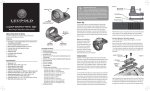
LMS-JMX-H; LMS-JMX-NH What’s in the Box Ⓒ Ⓐ Ⓘ Ⓕ Ⓐ Ⓑ Ⓒ Ⓓ Ⓔ Ⓕ Ⓖ Ⓗ Ⓘ Ⓙ Affix Laser Warning Label (I) onto your firearm as close to the laser as possible Ⓗ Ⓑ Ⓖ Ⓓ Ⓙ Ⓔ LEFT GRIP RIGHT GRIP LASER SIDE PLATE GRIP SCREW SIDE PLATE SCREWS (2) BATTERIES (2) LARGE HEX WRENCH (5/64) ALIGNMENT TOOL (.035”) LASER WARNING LABEL BATTERY COVER Installing the J-Max Laser System a b rem o ve Make sure your gun is unloaded. Double check to verify your handgun is safe before proceeding. Place left side of revolver grip frame over Left Grip (A), so that the grip frame aligns with features in Left Grip (A). (See Figure b) Place Laser Side Plate (C) over right side of grip frame, aligning it with grooves and screw holes in frame. (See Figure c) Insert Side Plate Screws (E) into holes in Laser Side Plate (C). Tighten with the Large Hex Wrench (G). Do not over tighten. (See Figure d) Position Right Grip (B) over Laser Sight Plate (C), aligning it with grooves & screw hole. DO NOT REMOVE screw below cylinder c d e TIME OUT! To avoid unintentional battery drain, the J-Max is set to turn off after 30 minutes of constant use. While in the time out mode, simply cycle the activation switch off to re-cycle the laser, and turn it back on. Unscrew the mounting hardware on your existing grips (in most cases this will be a single flat head screw; refer to gun owners manual for proper size) and remove grips. Remove the two (2) factory side plate screws. Do not remove factory side plate or side plate yoke screw! (See Figures a & b) Insert Grip Screw (D) into hole in Right Grip (B) and through frame. Secure with flat blade screwdriver. (See Figure e) Inserting the Batteries f Laser Side Plate (C) g h To insert or replace batteries: Using a small flat blade screwdriver, loosen the battery cover screw until the battery cover (J) is able to rotate. Rotate the battery cover (J) until you are able to remove the batteries. Replace the batteries by inserting the negative (-) end first. The batteries’ positive (+) printed side must face out. Rotate the battery cover to its original orientation. Tighten the battery cover screw until snug—do not over tighten. Confirm that the laser will now activate. If the laser will not turn on—retighten the screw and try again. (See Figures f-h) * Remove batteries when not in use for extended periods of time to preserve battery life. 1.800.527.3703 installation installationguide guide LMS-JMX-H; LMS-JMX-NH Changing The Laser Mode h One of the unique features of the J-Max Laser System is the ability to change the laser mode. The J-Max comes factory set for a modulated (pulsed) beam for higher visibility. To change this setting to a continuous wave (steady on) beam, follow these simple steps: Beam Selection Switch TOP Remove both Grips (A & B). the Beam Selection Switch on the Laser Side Switch Plate (C) to the left (See Figure h) Reassemble as usual. To return to modulated (pulsed) laser mode, repeat steps 1-3. Right = Pulsed; LEFT = Continuous Mode. Aligning The Laser For POA/POI You can easily fine tune your laser to accommodate any weapon platform, type of ammunition or shooting distance. sight in the laser, insert Alignment Tool (H) into To one of the holes at the top of the laser side plate (C). tune your laser alignment by slowly turning the Fine Alignment Tool (H), then checking your laser position against your iron sights & your POI (Point of Impact). One half turn will be roughly equal to an adjustment of two feet at twenty yards. The hole at the top adjusts elevation (vertical alignment).* *A clockwise turn lowers your elevation. **A clockwise turn moves your windage to the left. Use of a boresighter to sight in your laser is not recommended. Your POI will vary greatly depending on range and ammunition. The hole at the side adjusts windage (horizontal alignment).** NOTE: When installing J-Max for the first time, a slight shift in alignment may be noticed after firing, due to settling. Recheck alignment after your first trip to the range. Readjust if necessary. Storing Your Alignment Tool & Batteries Your J-Max laser comes with two (2) Alignment Tools (H) for your convenience. One tool can be stored on the inside of the Left Grip (A) for use on the range or in the field. A spare set of 357 Batteries (not included) can also be stored inside the Left Grip (A). Replacing batteries once a year is recommended. Adjustment Tool (F) SPARE PARTS LIST: Replacement Batteries: LMS-2x357; *Service Kit: LMS-JMX-SK *Service Kit includes: (1) Grip Screw (D), (2) Side Plate Screws (E), (1) Large Hex Wrench (G), (1) Alignment Tool (H), (1) Laser Warning Label (I), (1) Battery Cover (J), (2) Alignment Screws POWER OUTPUT: <5 mW DIODE LASER WAVELENGTH: 600-700 nm CLASS IIIa LASER PRODUCT AVOID DIRECT EXPOSURE TO BEAM 1.800.527.3703 1.800.527.3703 01785-0-21 MANUFACTURED BY LASERMAX, INC. 3495 WINTON PLACE ROCHESTER, NY 14623 USA Patent # US 6,591,536 other patents pending installation guide, installation continued guide REV C 6/07