1
XPort AR
User Guide
Part Number 900-405
Revision B November 2005
Copyright & Trademark
© 2005, Lantronix. All rights reserved. No part of the contents of this book may be
transmitted or reproduced in any form or by any means without the written permission
of Lantronix. Printed in the United States of America.
Ethernet is a trademark of XEROX Corporation. UNIX is a registered trademark of
The Open Group. Windows 95, Windows 98, Windows 2000, and Windows NT are
trademarks of Microsoft Corp. Netscape is a trademark of Netscape Communications
Corporation.
Contacts
Lantronix Corporate Headquarters
15353 Barranca Parkway
Irvine, CA 92618, USA
Phone: 949-453-3990
Fax:
949-453-3995
Technical Support
Phone: 800-422-7044 or 949-453-7198
Fax:
949-450-7226
Online: www.lantronix.com/support
Sales Offices
For a current list of our domestic and international sales offices, go to the Lantronix
web site at www.lantronix.com/about/contact.
Disclaimer & Revisions
Note: This product has been designed to comply with the limits for a Class B digital
device pursuant to Part 15 of FCC and EN55022:1998 Rules when properly enclosed
and grounded. These limits are designed to provide reasonable protection against
radio interference in a residential installation. This equipment generates, uses, and
can radiate radio frequency energy, and if not installed and used in accordance with
this guide, may cause interference to radio communications.
The information in this guide may change without notice. The manufacturer assumes
no responsibility for any errors that may appear in this guide.
Date
Rev. Comments
6/2005 A
11/2005 B
XPort AR User Guide
Initial Document
Added V2.0 software information
2
Contents
Figures
7
Tables
8
1: Using This Guide
9
Purpose and Audience _______________________________________________ 9
Summary of Chapters ________________________________________________ 9
Additional Documentation ____________________________________________ 10
2: Description and Specifications
11
Features _________________________________________________________ 11
Applications _______________________________________________________ 11
Protocol Support ___________________________________________________ 12
Additional Features _________________________________________________ 12
Configuration Methods ______________________________________________ 12
Addresses and Port Numbers _________________________________________ 13
Hardware Address ______________________________________________________ 13
IP Address_____________________________________________________________ 13
Port Numbers __________________________________________________________ 13
Product Information Label ____________________________________________ 14
3: Using DeviceInstaller
15
Accessing XPort AR using DeviceInstaller _______________________________ 15
Viewing the XPort AR’s Current Configuration ____________________________ 15
4: Configuration Using Web Manager
17
Accessing Web Manager through a Web Browser _________________________ 17
Network Settings ___________________________________________________ 18
Network Configuration ___________________________________________________ 18
Protocol Stack Configuration ______________________________________________ 19
PPP __________________________________________________________________ 21
DNS Configuration ______________________________________________________ 22
SNMP Configuration _____________________________________________________ 22
FTP Configuration _______________________________________________________ 23
TFTP Configuration______________________________________________________ 24
IP Address Filter ________________________________________________________ 25
Query Port_____________________________________________________________ 25
Line 1, Line 2, and Line 3 Settings _____________________________________ 26
XPort AR User Guide
3
Contents
Line 1 Configuration _____________________________________________________ 26
Line 1 Command Mode___________________________________________________ 27
Tunnel 1 and Tunnel 2 Settings________________________________________ 28
Serial Settings __________________________________________________________ 29
Connect Mode__________________________________________________________ 30
Accept Mode ___________________________________________________________ 31
Disconnect Mode _______________________________________________________ 33
Packing Mode __________________________________________________________ 33
Start and Stop Characters ________________________________________________ 34
Modem Emulation _______________________________________________________ 35
AES Keys – Connect Mode _______________________________________________ 36
AES Keys – Accept Mode_________________________________________________ 37
Configurable Pin Manager____________________________________________ 38
CPM: Configurable Pins __________________________________________________ 38
CPM: Groups __________________________________________________________ 40
SSH Settings ______________________________________________________ 42
SSH Server’s Host Keys __________________________________________________ 42
SSH Server’s Authorized Users ____________________________________________ 43
SSH Client Known Hosts _________________________________________________ 44
SSH Client User Configuration _____________________________________________ 44
SSL Settings ______________________________________________________ 46
Command Line Interface Settings ______________________________________ 47
CLI Configuration _______________________________________________________ 47
HTTP Settings _____________________________________________________ 48
HTTP Configuration _____________________________________________________ 49
HTTP Authentication _____________________________________________________ 50
HTTP RSS ____________________________________________________________ 51
XML Configuration__________________________________________________ 52
Import System Configuration ______________________________________________ 52
Export System Configuration ______________________________________________ 54
Email Configuration _________________________________________________ 55
Filesystem Configuration _____________________________________________ 56
Diagnostics Configuration ____________________________________________ 59
MIB2 Statistics _________________________________________________________ 59
IP Sockets _____________________________________________________________ 59
Ping __________________________________________________________________ 60
Traceroute_____________________________________________________________ 61
DNS Lookup ___________________________________________________________ 61
Memory _______________________________________________________________ 62
XPort AR User Guide
4
Contents
Buffer Pools____________________________________________________________ 62
Processes _____________________________________________________________ 63
Hardware______________________________________________________________ 64
System Configuration _______________________________________________ 64
5: Configuration Using Telnet or Serial Port
66
Accessing Command Mode___________________________________________ 66
Using Telnet ___________________________________________________________ 66
Using the Serial Port _____________________________________________________ 66
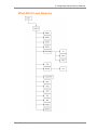
Navigating the Command Line Interface _________________________________ 67
Root Configuration Menu_____________________________________________ 68
Enable Menu ______________________________________________________ 70
Chem Menu _______________________________________________________ 74
Configure Menu ____________________________________________________ 78
Interface 1 Level Menu ______________________________________________ 88
PPP Menu ________________________________________________________ 91
CPM Menu________________________________________________________ 92
Device Menu ______________________________________________________ 94
DVT _____________________________________________________________ 95
Filesystem Menu ___________________________________________________ 96
Line Menu ________________________________________________________ 99
SSH Menu _______________________________________________________ 103
SSL Menu _______________________________________________________ 106
Tunnel Menu _____________________________________________________ 107
6: Point-to-Point Protocol (PPP)
119
7: Tunneling
120
Connect Mode ____________________________________________________ 120
Accept Mode _____________________________________________________ 121
Disconnect Mode__________________________________________________ 122
Packing Mode ____________________________________________________ 122
Modem Emulation _________________________________________________ 123
Command Mode _______________________________________________________ 123
Serial Line Settings ________________________________________________ 124
Statistics ________________________________________________________ 124
8: SSH and SSL Security
125
Secure Shell: SSH_________________________________________________ 125
SSH Server Configuration________________________________________________ 125
XPort AR User Guide
5
Contents
SSH Client Configuration ________________________________________________ 126
Secure Sockets Layer: SSL__________________________________________ 126
9: Using Email
128
SMTP Configuration _______________________________________________ 128
Priority Levels ____________________________________________________ 129
DNS Records_____________________________________________________ 129
Extended Hello ___________________________________________________ 129
Email Statistics ___________________________________________________ 129
10: Configuration Pin Manager
131
Configurable Pins _________________________________________________ 131
CP Groups_______________________________________________________ 132
11: XML
134
XML Configuration Record Schema ___________________________________ 134
Configuration using XML ____________________________________________ 136
XML Groups _____________________________________________________ 137
Import-Only Groups ____________________________________________________ 137
12: Branding the XPort AR
150
Web Manager Customization ________________________________________ 150
Command Mode __________________________________________________ 150
13: Updating Firmware
151
Obtaining Firmware ________________________________________________ 151
Loading New Firmware _____________________________________________ 151
A: Technical Support
152
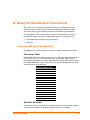
B: Binary to Hexadecimal Conversions
153
Converting Binary to Hexadecimal ____________________________________ 153
Conversion Table ______________________________________________________ 153
Scientific Calculator ____________________________________________________ 153
Compliance Information
155
Warranty
156
XPort AR User Guide
6
Contents
Figures
Figure 2-1. Sample Hardware Address ................................................................................................13
Figure 2-2. Product Label ....................................................................................................................14
Figure 4-1. Web Manager Home Page ................................................................................................17
Figure 4-2. Network Configuration........................................................................................................18
Figure 4-3. Protocol Stack ....................................................................................................................20
Figure 4-4. PPP Settings ......................................................................................................................21
Figure 4-5. DNS Settings......................................................................................................................22
Figure 4-6. SNMP Configuration ..........................................................................................................23
Figure 4-7. FTP Configuration ..............................................................................................................24
Figure 4-8. TFTP Configuration............................................................................................................24
Figure 4-9. IP Address Filter Configuration ..........................................................................................25
Figure 4-10. Query Port Configuration .................................................................................................26
Figure 4-11. Line 1 Configuration .........................................................................................................27
Figure 4-12. Line 1 Command Mode....................................................................................................28
Figure 4-13. Tunnel 1 ...........................................................................................................................29
Figure 4-14. Tunnel 1 Serial Settings ...................................................................................................29
Figure 4-15. Tunnel 1 Connect Mode...................................................................................................30
Figure 4-16. Tunnel 1 Accept Mode .....................................................................................................32
Figure 4-17. Tunnel 1 Disconnect Mode ..............................................................................................33
Figure 4-18. Tunnel 1 Packing Mode ...................................................................................................34
Figure 4-19. Tunnel 1 Start/Stop Chars ...............................................................................................35
Figure 4-20. Tunnel 1 Modem Emulation .............................................................................................35
Figure 4-21. AES Keys – Connect........................................................................................................36
Figure 4-22. AES Keys – Accept ..........................................................................................................37
Figure 4-23. CPM: CPs ........................................................................................................................38
Figure 4-24. CPM: Groups ...................................................................................................................40
Figure 4-25. SSH Server: Host Keys....................................................................................................42
Figure 4-26. SSH Server: Authorized Users ........................................................................................43
Figure 4-27. SSH Client: Known Hosts ................................................................................................44
Figure 4-28. SSH Client: Users ............................................................................................................45
Figure 4-29. SSL...................................................................................................................................46
Figure 4-30. Command Line Interface Statistics ..................................................................................47
Figure 4-31. Command Line Interface Configuration ...........................................................................48
Figure 4-32. HTTP Statistics ................................................................................................................49
Figure 4-33. HTTP Configuration .........................................................................................................49
Figure 4-34. HTTP Authentication ........................................................................................................51
Figure 4-35. HTTP RSS .......................................................................................................................52
Figure 4-36. Import System Configuration ...........................................................................................53
Figure 4-37. Export System Configuration ...........................................................................................54
Figure 4-38. Email Statistics.................................................................................................................55
Figure 4-39. Email Configuration..........................................................................................................55
Figure 4-40. Filesystem ........................................................................................................................56
Figure 4-41. Filesystem Browser..........................................................................................................57
Figure 4-42. MIB2 Network Statistics ...................................................................................................59
Figure 4-43. IP Sockets ........................................................................................................................60
Figure 4-44. Diagnostics: Ping .............................................................................................................60
Figure 4-45. Diagnostics: Traceroute ...................................................................................................61
Figure 4-46. Diagnostics: DNS Lookup ................................................................................................61
Figure 4-47. Diagnostics: Memory........................................................................................................62
Figure 4-48. Diagnostics: Buffer Pools.................................................................................................63
Figure 4-49. Diagnostics: Processes....................................................................................................63
Figure 4-50. Diagnostics: Hardware .....................................................................................................64
Figure 4-51. System .............................................................................................................................65
Figure 11-1. XML Group Example......................................................................................................135
XPort AR User Guide
7
Contents
Figure 11-2. XML Example With Multiple Named Values ..................................................................136
Figure 11-3. XML Example With Multiple Items .................................................................................136
Figure 11-4. XML Example With Multiple Groups ..............................................................................136
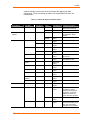
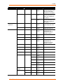
Tables
Table 11-1. XPort AR Import and Export Groups...............................................................................138
XPort AR User Guide
8
1: Using This Guide
Purpose and Audience
This guide provides the information needed to configure, use, and update the XPort
AR™. It is intended for software developers and system integrators who are
embedding the XPort AR in their designs.
Summary of Chapters
The remaining chapters in this guide include:
Chapter
Description
2: Description and
Specifications
Main features of the product and the protocols it supports.
Includes technical specifications.
3:Using DeviceInstaller
Instructions for viewing the current configuration using
DeviceInstaller.
4:Configuration Using Web
Manager
Instructions for accessing Web Manager and using it to
configure settings for the XPort AR.
5:Configuration Using Telnet or
Serial Port
Instructions for accessing Command Mode (the command
line interface) using a Telnet connection through the
network or through the serial port. Detailed information
about the commands.
6:Point-to-Point Protocol (PPP)
Overviews PPP on the XPort AR.
7:Tunneling
Information on tunneling features available on the serial
lines.
8:SSH and SSL Security
Overview and configuration of SSH and SSL security
settings.
9:Using Email
Information on the SMTP server and setting email
parameters on the XPort AR.
10:Configuration Pin Manager
Information on the Configuration Pin Manager (CPM) and
setting the configurable pins to work with a device.
11:XML
Configuring the XPort AR using XML.
12:Branding the XPort AR
Instructions for customizing the XPort AR.
13:Updating Firmware
Instructions for obtaining the latest firmware and updating
the XPort AR.
A: Technical Support
How to contact Lantronix Technical Support.
B: Binary to Hexadecimal
Instructions for converting binary values to hexadecimal and
tables listing all configuration options in hexadecimal
notation.
XPort AR User Guide
9
1: Using This Guide
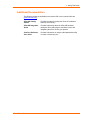
Additional Documentation
The following guides are available on the product CD or the Lantronix Web site
(www.lantronix.com):
XPort AR Getting
Started
Provides the steps for getting the XPort AR evaluation
board up and running.
XPort AR Integration
Guide
Provides information about the XPort AR hardware,
testing the XPort AR using the evaluation board, and
integrating the XPort AR into your product.
Com Port Redirector
User Guide
Provides information on using the Windows-based utility
to create a virtual com port.
XPort AR User Guide
10
2: Description and Specifications
This chapter summarizes the XPort AR device server’s features and basic
information needed before getting started.
Features
The XPort AR is designed with additional features above and beyond the original
XPort, including:
The Evolution OS operating system
Two full serial ports with all hardware handshaking signals or three serial ports
without handshaking signals
11 configurable pins
Supports fully compliant PoE designs by using PoE compliant magnetics and
passing through both the used and unused pairs
Increased memory: 4MB Flash and 1.25MB RAM
Hardware capability in place to allow future software support for:
−
−
−
−
−
−
I2C Bus
SPI Bus
CAN Bus
USB
External interrupts, including one non-maskable
Timer input
Applications
The XPort AR device server connects serial devices such as those listed below to
Ethernet networks using the IP protocol family.
ATM machines
CNC controllers
Data collection devices
Universal Power Supply (UPS) management units
Telecommunications equipment
Data display devices
Security alarms and access control devices
Handheld instruments
Modems
XPort AR User Guide
11
2: Description and Specifications
Time/attendance clocks and terminals
Protocol Support
The XPort AR device server contains a full-featured TCP/IP stack. Supported
protocols include:
ARP, IP, UDP, TCP, ICMP, BOOTP, DHCP, Auto IP, Telnet, FTP, TFTP, HTTP,
SSH, SSL, SNMP, and SMTP for network communications and management.
TCP, UDP, TCP/AES, UDP/AES, Telnet, and SSH for tunneling to the serial port.
TFTP, FTP, and HTTP for firmware upgrades and uploading files.
Additional Features
Modem Emulation: In modem emulation mode, the XPort AR can replace dial-up
modems. The unit accepts modem AT commands on the serial port, and then
establishes a network connection to the end device, leveraging network connections
and bandwidth to eliminate dedicated modems and phone lines.
Built-in Web Server: The XPort AR includes a built-in web server (Web Manager)
for configuring the unit and displaying statistics.
Command Line Interface: A Command Line Interface (CLI) is available for
configuration via the serial port or Telnet.
Configurable Pin Manager: The XPort AR contains a Configurable Pin Manager
(CPM) accessible through the CLI or Web Manager to configure and manage the
XPort AR’s 11 configurable pins.
XML: To quickly configure multiple XPort AR units, export a configured XPort AR’s
configuration as an XML file. Import this file into other XPorts without having to
repeat the configuration steps.
Power over Ethernet (PoE): The XPort AR supports PoE (also known as the IEEE
standard 802.3af). Conventionally, network devices require a connection to the
network and a power connection. PoE provides power to network devices over an
Ethernet connection if the required hardware is available. The XPort AR passes PoE
through the RJ45 to a connector on the bottom. To enable PoE, take the
connections and design a PoE circuit and regulator to provide power for the device
connected to the XPort AR. The XPort AR passes power not only through unused
pairs, but through communications pairs as well.
Configuration Methods
After installation, the XPort AR requires configuration. For the unit to operate
correctly on a network, it must have a unique IP address on the network. There are
three basic methods for logging into the XPort AR and assigning IP addresses and
other configurable settings:
DeviceInstaller: Configure the IP address and view network settings on the XPort
AR using a Graphical User Interface (GUI) on a PC attached to a network. (See
3:Using DeviceInstaller.)
XPort AR User Guide
12
2: Description and Specifications
Web Manager: Through a web browser, configure the XPort AR’s settings using the
Lantronix Web Manager. (See 4:Configuration Using Web Manager.)
Command Mode: There are two methods to accessing Command Mode: making a
Telnet connection or connecting a terminal (or a PC running a terminal emulation
program) to the unit’s serial port. (See 5:Configuration Using Telnet or Serial Port.)
Addresses and Port Numbers
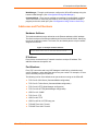
Hardware Address
The hardware address is also referred to as the Ethernet address or MAC address.
The first three bytes of the Ethernet address are fixed and read 00-20-4A, identifying
the unit as a Lantronix product. The fourth, fifth, and sixth bytes are unique numbers
assigned to each unit.
Figure 2-1. Sample Hardware Address
00-20-4A-14-01-18 or 00:20:4A:14:01:18
IP Address
Every device connected to an IP network must have a unique IP address. This
address references the specific unit.
Port Numbers
Every TCP connection and every UDP datagram is defined by a destination and
source IP address, and a destination and source port number. For example, a Telnet
server commonly uses port number 23.
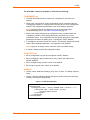
The following is a list of the default server port numbers running on the XPort AR:
TCP Port 22: SSH Server (Command Mode configuration)
TCP Port 23: Telnet Server (Command Mode configuration)
TCP Port 80: HTTP (Web Manager configuration)
TCP Port 443: HTTPS (Web Manager configuration)
UDP Port 161: SNMP
TCP Port 21: FTP
UDP Port 69: TFTP
UDP Port 30718: 0x77FE Query port
TCP/UDP Port 1001: Tunnel 1
TCP/UDP Port 1002: Tunnel 2
XPort AR User Guide
13
2: Description and Specifications
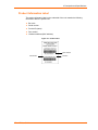
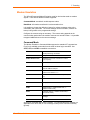
Product Information Label
The product information label on the underside of the unit contains the following
information about the specific unit:
Bar code
Serial number
Product ID (name)
Part number
Hardware address (MAC address)
Figure 2-2. Product Label
MAC Address
Part Number
XPort AR User Guide
Revision
14
3: Using DeviceInstaller
This chapter covers the steps for viewing the XPort AR device server’s properties
and device details.
Accessing XPort AR using DeviceInstaller
Note: Make note of the MAC address. It is needed to locate the XPort AR
using DeviceInstaller.
Follow the instructions on the product CD to install and run DeviceInstaller.
1. Click StartÆPrograms Æ LantronixÆDeviceInstallerÆDeviceInstaller.
2. Click on the XPort AR folder. The list of Lantronix XPort AR devices available
displays.
3. Expand the list of XPorts by clicking the + symbol next to the XPort AR icon.
Select the XPort AR unit by clicking on its IP address to view its configuration.
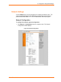
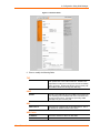
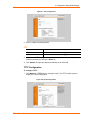
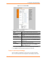
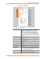
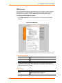
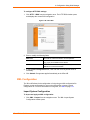
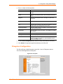
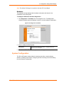
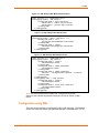
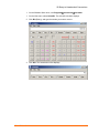
Viewing the XPort AR’s Current Configuration
1. In the right window, click the Device Details tab. The current XPort AR
configuration displays:
Name
Configurable field. Enter a name to identify the XPort AR.
Double-click on the field, type in the value, and press Enter to
complete. This name is not visible on other PCs or laptops
using DeviceInstaller.
Group
Configurable field. Enter a group to categorize the XPort AR.
Double-click on the field, type in the value, and press Enter to
complete. This group name is not visible on other PCs or
laptops using DeviceInstaller.
Comments
Configurable field. Enter comments for the XPort AR.
Double-click on the field, type in the value, and press Enter to
complete. This description or comment is not visible on other
PCs or laptops using DeviceInstaller.
Device Family
Non-configurable field. Displays the XPort AR’s device family
type as XPort AR.
Type
Non-configurable field. Displays the device type as XPort AR.
ID
Non-configurable field. Displays the XPort AR’s ID embedded
within the box.
Hardware Address
Non-configurable field. Displays the XPort AR’s hardware (or
MAC) address.
Firmware Version
Non-configurable field. Displays the firmware currently
installed on the XPort AR.
XPort AR User Guide
15
3: Using DeviceInstaller
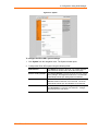
Extended Firmware
Version
Provides additional information on the firmware version.
Online Status
Non-configurable field. Displays the XPort AR’s status as
online, offline, unreachable (the XPort AR is on a different
subnet), or busy (the XPort AR is currently performing a task).
Telnet Enabled
Displays whether Telnet is enabled on this XPort AR.
Telnet Port
Non-configurable field. Displays the XPort AR’s port for telnet
sessions.
Web Enabled
Displays whether Web Manager access is enabled on this
XPort AR.
WebPort
Non-configurable field. Displays the XPort AR’s port for Web
Manager configuration.
Maximum Baud Rate
Supported
Non-configurable field. Displays the XPort AR’s maximum
baud rate.
Note: the XPort AR may not currently be running at this rate.
Firmware Upgradeable
Non-configurable field. Displays True, indicating the XPort
AR’s firmware is upgradeable as newer version become
available.
IP Address
Displays the XPort AR’s current IP address. To change the IP
address, click on the Assign IP button on the DeviceInstaller
menu bar.
Supports Configurable
Pins
Non-configurable field. Displays True, indicating configurable
pins are available on the XPort AR.
Supports Email Triggers
Non-configurable field. Displays True, indicating email
triggers are available on the XPort AR.
XPort AR User Guide
16
4: Configuration Using Web Manager
This chapter describes how to configure the XPort AR using Web Manager,
Lantronix’s browser-based configuration tool. The unit’s configuration is stored in
nonvolatile memory and is retained without power. All changes take effect
immediately, unless otherwise noted.
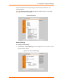
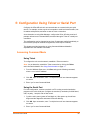
Accessing Web Manager through a Web Browser
Log into the XPort AR using a standard Web browser.
Note: Alternatively, access the Web Manager by selecting the Web
Configuration tab from DeviceInstaller.
To access Web Manager:
1. Open a standard web browser (such as Netscape Navigator 6.x and above,
Internet Explorer 5.5. and above, Mozilla Suite, Mozilla Firefox, or Opera).
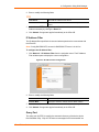
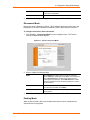
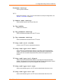
2. Enter the IP address of the XPort AR in the address bar. The Web Manager
home page displays.
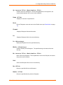
Note: The XPort AR Status page (the home page) displays the common
XPort AR configuration and product information.
Figure 4-1. Web Manager Home Page
XPort AR User Guide
17
4: Configuration Using Web Manager
Network Settings
Click the Network link on the left navigation bar to display the Network menu. The
sub-menus displayed allow for the configuration of the general network settings,
protocol stack, DNS, SNMP, FTP, TFTP, IP address filter, and the query port.
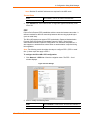
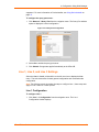
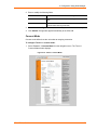
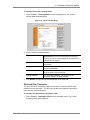
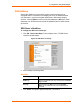
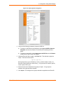
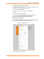
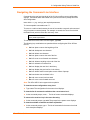
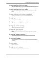
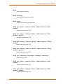
Network Configuration
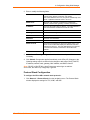
To configure the network’s general configuration:
1. Click Network Æ Configuration from the navigation menu. The Network
Configuration window displays.
Figure 4-2. Network Configuration
XPort AR User Guide
18
4: Configuration Using Web Manager
2. Enter or modify the following fields:
BOOTP Client
Select On or Off. Overrides the configured IP address,
network mask, gateway, hostname, and domain.
Note: When DHCP is set to On, the system automatically uses
DHCP, regardless if BOOTP Client is set to On.
DHCP Client
Select On, Off, or Renew. Overrides the configured IP
address, network mask, gateway, hostname, and domain.
IP Address
Enter the XPort AR’s static IP address. The static address is
used when BOOTP and DHCP are both set to Off.
Network Mask
Enter the XPort AR’s network mask.
Gateway
Enter the XPort AR’s gateway address.
MAC Address
Enter the XPort AR’s new MAC address.
Hostname
Enter the unit’s hostname.
Domain
Enter the unit’s domain name.
DHCP Client ID
Enter the ID if a DHCP ID is used by the DHCP server. The
DHCP server’s lease table displays IP addresses and MAC
addresses for devices. The lease table displays the Client ID,
in hexadecimal notation, instead of the XPort AR’s MAC
address.
Ethernet
Select the speed for Ethernet transmission.
3. In the Current Running Configuration table, delete currently stored fields as
necessary.
4. Click Submit. Changes are applied immediately to the XPort AR. Changes to the
following settings require a reboot for the changes to take effect: DHCP, BOOTP,
IP address, network mask, gateway, MAC address, and DHCP client ID.
Note: If DHCP or BOOTP fails, AutoIP intervenes and assigns an address.
In this case, the static IP (if configured) is ignored.
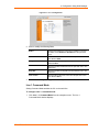
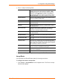
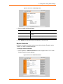
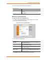
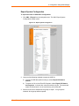
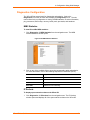
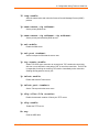
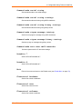
Protocol Stack Configuration
To configure the XPort AR’s network stack protocols:
1. Click Network Æ Protocol Stack from the navigation menu. The Protocol Stack
window displays the settings for TCP, ICMP, and ARP.
XPort AR User Guide
19
4: Configuration Using Web Manager
Figure 4-3. Protocol Stack
2. Enter or modify the following fields:
TCP
Send RSTs
TCP contains six control bits, with one or more defined in
each packet. RST is one of the control bits. The RST bit is
responsible for telling the receiving TCP stack to immediately
end a connection. Sending this flag may pose a security risk.
Select Off to disable the sending of the RST flag.
ICMP
Enable
Internet Control Message Protocol (ICMP) can be used as an
error-reporting protocol between two hosts. Commands such
as ping use this protocol. Sending and processing ICMP
messages may post a security risk.
ARP
ARP Timeout
Enter the time, in milliseconds, for the ARP timeout. This is
the duration an address remains in the cache.
ARP Cache
IP Address
Enter the IP address to add to the ARP table.
MAC Address
Enter the MAC address to add to the ARP table.
XPort AR User Guide
20
4: Configuration Using Web Manager
Note: Both the IP and MAC addresses are required for the ARP cache.
Current State
Clear
Select Clear to remove all entries in the ARP table.
Remove
Removes a specific entry from the ARP table.
3. Click Submit after each modified field. Changes are applied immediately to the
XPort AR.
PPP
Point-to-Point Protocol (PPP) establishes a direct connection between two nodes. It
defines a method for data link connectivity between devices using physical layers
(such as serial lines).
The XPort AR supports two types of PPP authorization: Password Authentication
Protocol (PAP) and Challenge Handshake Protocol (CHAP). Both of these
authentication methods require the configuration of a username and password. It
also supports no authentication scheme when no authentication is required during
link negotiation.
Note: The following section describes the steps to configure PPP 1 (PPP on serial
line 1); these steps also apply to PPP 2.
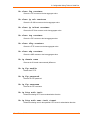
To configure the XPort AR’s PPP configuration:
1. Click Network Æ PPP Line 1 from the navigation menu. The PPP – Line 1
window displays.
Figure 4-4. PPP Settings
2. Enter or modify the following fields:
Mode
Select Enabled to enable PPP on the XPort AR’s serial line 1.
Local IP Address
Enter the IP address assigned to the device’s PPP interface.
XPort AR User Guide
21
4: Configuration Using Web Manager
Peer IP Address
Enter the IP address assigned to the peer (when requested
during negotiation).
Network Mask
Enter the network mask.
Auth. Mode
Choose the authentication mode. Select None when no
authentication is required. Select PAP for Password
Authentication Protocol. Select CHAP for the Challenge
Handshake Authentication Protocol.
3. Click Submit. Changes are applied immediately to the XPort AR
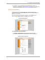
DNS Configuration
To configure the XPort AR’s DNS configuration:
1. Click Network Æ DNS from the navigation menu. The DNS window displays.
Figure 4-5. DNS Settings
2. Enter or modify the following fields:
DNS
Primary Server
Enter the DNS primary server address.
Secondary Server
Enter the DNS secondary server address.
Current Configuration
Primary Server
Displays the current Primary Server address. Select Delete
to remove this value.
Secondary Server
Displays the current Secondary Server address. Select
Delete to remove this value.
3. Click Submit. Changes are applied immediately to the XPort AR.
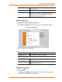
SNMP Configuration
To configure SNMP:
1. Click Network Æ SNMP from the navigation menu. The SNMP window opens
and displays the current SNMP configuration.
XPort AR User Guide
22
4: Configuration Using Web Manager
Figure 4-6. SNMP Configuration
2. Enter or modify the following fields:
SNMP Agent
Select On to enable SNMP.
Read Community
Enter the SNMP read-only community string.
Write Community
Enter the SNMP read/write community string.
System Contact
Enter the name of the system contact.
System Name
Enter the system name.
System Description
Enter the system description.
System Location
Enter the system location.
Enable Traps
Select On to enable the transmission of the SNMP cold start
trap messages. This trap is generated during system boot.
Primary TrapDest IP
Enter the primary SNMP trap host.
Secondary TrapDest IP
Enter the secondary SNMP trap host.
3. In the Current Configuration table, delete and clear currently stored fields as
necessary.
4. Click Submit. Changes are applied immediately to the XPort AR.
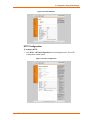
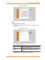
FTP Configuration
To configure FTP:
1. Click Network Æ FTP from the navigation menu. The FTP window opens to
display the current configuration.
XPort AR User Guide
23
4: Configuration Using Web Manager
Figure 4-7. FTP Configuration
2. Enter or modify the following fields:
FTP
FTP Server
Select On to enable the FTP server.
Username
Enter the username to use when logging in via FTP.
Password
Enter the password to use when logging in via FTP.
3. In the Current FTP Configuration and Statistics tables, reset currently stored
fields as necessary by clicking the Reset link.
4. Click Submit. Changes are applied immediately to the XPort AR.
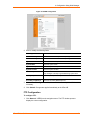
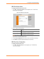
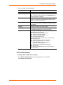
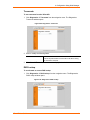
TFTP Configuration
To configure TFTP:
1. Click Network Æ TFTP from the navigation menu. The TFTP window opens to
display the current configuration.
Figure 4-8. TFTP Configuration
XPort AR User Guide
24
4: Configuration Using Web Manager
2. Enter or modify the following fields:
TFTP
TFTP Server
Select On to enable the FTP server.
Allow TFTP File Creation
Enable the automatic creation of files stored by the TFTP
server.
3. In the Current TFTP Configuration and Statistics table, reset currently stored
fields as necessary by clicking the Reset link.
4. Click Submit. Changes are applied immediately to the XPort AR.
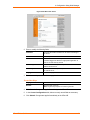
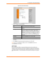
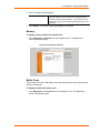
IP Address Filter
The IP address filter specifies the hosts and subnets permitted to communicate with
the XPort AR.
Note: If using DHCP/BOOTP, ensure the DHCP/BOOTP server is in this list.
To configure the IP address filter:
1. Click Network Æ IP Address Filter from the navigation menu. The IP Address
Filter window opens to display the current configuration.
Figure 4-9. IP Address Filter Configuration
2. Enter or modify the following fields:
IP Address
Enter the IP address to add to the IP filter table.
Network Mask
Enter the IP address’ network mask in dotted notation.
3. In the Current State table, click Remove to delete fields as necessary.
4. Click Submit. Changes are applied immediately to the XPort AR.
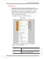
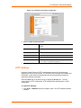
Query Port
The query port (0x77FE) is used for the automatic discovery of the device by the
DeviceInstaller utility. Only 0x77FE discover messages from DeviceInstaller are
XPort AR User Guide
25
4: Configuration Using Web Manager
supported. For more information on DeviceInstaller, see Using DeviceInstaller on
page 15.
To configure the query port server:
1. Click Network Æ Query Port from the navigation menu. The Query Port window
opens to display the current configuration.
Figure 4-10. Query Port Configuration
2. Select On to enable the query port server.
3. Click Submit. Changes are applied immediately to the XPort AR.
Line 1, Line 2, and Line 3 Settings
Select the Line 1, Line 2, or Line 3 link on the left menu bar to display the Line
menu. The sub-menus allow for both general configuration and command mode
configuration.
Note: The following section describes the steps to configure Line 1; these steps also
apply to Line 2 and Line 3 menu options.
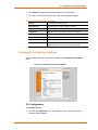
Line 1 Configuration
To configure Line 1:
1. Click Line 1 Æ Configuration from the navigation menu. The Line 1
Configuration window displays.
XPort AR User Guide
26
4: Configuration Using Web Manager
Figure 4-11. Line 1 Configuration
2. Enter or modify the following fields:
Status
Displays the whether the current line is enabled. To change
the status, select Enabled or Disabled from the pull-down
menu.
Baud Rate
Select the XPort AR’s baud rate from the pull-down menu.
The default is 9600.
Parity
Select the XPort AR’s parity from the pull-down menu. The
default is None.
Data Bits
Select the number of data bits from the pull-down menu. The
default is 8.
Stop Bits
Select the number of stop bits from the pull-down menu. The
default is 1.
Flow Control
Select the XPort AR’s flow control from the pull-down menu.
The default is None.
3. Click Submit. Changes are applied immediately to the XPort AR.
Line 1 Command Mode
Setting Command Mode enables the CLI on the serial line.
To configure Line 1’s command mode:
1. Click Line 1 Æ Command Mode from the navigation menu. The Line 1
Command Mode window displays.
XPort AR User Guide
27
4: Configuration Using Web Manager
Figure 4-12. Line 1 Command Mode
2. Enter or modify the following fields:
Always
Select Yes to enable the XPort AR’s command mode.
Use Serial String
Select Yes to start command mode based on a serial string.
Use CP Group
Select Yes to start command mode based on the value of a
CP group.
Echo Serial String
Select Yes to enable echoing of the serial string at boot-up.
Wait Time
Enter the wait time for the serial string during boot-up.
Serial String
In the Char field, enter the serial string characters. Select the
string type from the pull down menu as Character, Binary, or
Decimal notation.
CP Group
Enter the CP group name and its value.
Signon Message
In the Char field, enter the boot-up signon message. Select
the string type from the pull down menu as Character,
Binary, or Decimal notation.
3. In the Current Configuration table, clear currently stored fields as necessary.
4. Click Submit. Changes are applied immediately to the XPort AR.
Tunnel 1 and Tunnel 2 Settings
Select the Tunnel 1 or Tunnel 2 link on the left menu bar to display the Tunnel
menu. The sub-menus allow for the configuration of serial settings, connect mode,
XPort AR User Guide
28
4: Configuration Using Web Manager
accept mode, disconnect mode, packing mode, start and stop characters, and
modem emulation.
Note: The following section describes the steps to configure Tunnel 1; these steps
also apply to Tunnel 2 menu options.
Figure 4-13. Tunnel 1
Serial Settings
To configure serial settings:
1. Click Tunnel 1 Æ Serial Settings from the navigation menu. The Tunnel 1 Serial
Settings window displays.
Figure 4-14. Tunnel 1 Serial Settings
XPort AR User Guide
29
4: Configuration Using Web Manager
2. Enter or modify the following fields:
Buffer Size
Enter the buffer size used for the tunneling of data received.
Read Timeout
Enter the time, in milliseconds, for tunneling wait for serial
data
Wait for Read Timeout
Select Enabled to cause the tunneling to wait for a read
timeout before returning serial data.
3. In the Current Configuration table, reset currently stored fields as necessary.
4. Click Submit. Changes are applied immediately to the XPort AR.
Connect Mode
Connect mode defines how the unit makes an outgoing connection.
To configure Tunnel 1’s connect mode:
1. Select Tunnel 1 Æ Connect Mode from the navigation menu. The Tunnel 1
Connect Mode window displays.
Figure 4-15. Tunnel 1 Connect Mode
XPort AR User Guide
30
4: Configuration Using Web Manager
2. Enter or modify the following fields:
Mode
Select Disabled to turn off connect mode. Any Character
enables connect mode upon receiving a character. Start
Character enables connect mode upon receiving the start
character. Select DSR Active to enable Connect Mode if
Data Set Ready (DSR) pin is active on the serial line. Select
Modem Emulation to use modem emulation on this tunnel.
Remote Address
Enter the remote address to which the XPort AR will connect.
Enter an IP address or DNS name.
Remote Port
Enter the remote port number.
Local Port
Enter the port for use as the local port. A random port is
selected by default.
Protocol
Select the protocol type for use in command mode. TCP is
the default protocol.
Reconnect Timer
Enter the reconnect time in milliseconds. The XPort AR
attempts to reconnect this amount of time after failing a
connection or exiting an existing connection.
SSH Username
Enter the SSH username. The tunnel uses the SSH keys for
the client username.
Block Serial Data
Select On to block (not tunnel) serial data transmitted to the
XPort AR.
Block Network Data
Select On to block (not tunnel) network data transmitted to the
XPort AR.
TCP Keep Alive
Enter the time, in milliseconds, the unit waits during a silent
connection before checking if the currently connected network
device is still on the network. If the unit then gets no response
after 8 attempts, it drops that connection.
CP Set Group
Identifies a CP or CP Group whose value should change
when a connection is established and dropped.
On Connection
Specifies the value to set the CP or CP Group when a
connection is established.
On Disconnection
Specifies the value used when the connection is closed.
3. Click Submit. Changes are applied immediately to the XPort AR.
Accept Mode
In accept mode, the XPort AR listens (waits) for incoming connections.
To configure the tunnel’s accept mode:
1. Click Tunnel 1 Æ Accept Mode from the navigation menu. The Tunnel 1 Accept
Mode window displays.
XPort AR User Guide
31
4: Configuration Using Web Manager
Figure 4-16. Tunnel 1 Accept Mode
2. Enter or modify the following fields:
Mode
Select Disabled to disable Accept Mode completely. Select
Enable to enable Accept Mode at all times. Select Any
Character to enable Accept Mode upon receiving any
character or select Start Character to enable Accept Mode
upon receiving the start character. Select DSR Active to
enable Accept Mode if the Data Set Ready (DSR) pin is active
on the serial line. In general, a modem sends a DSR signal to
its attached computer to indicate that the modem is ready to
operate.
Local Port
Enter the port number for use as the local port. The default is
port 10001.
Protocol
Select the protocol type for use with Accept Mode. The
default protocol is TCP.
Flush Serial Data
Select Enabled to flush the serial data buffer on a new
connection.
Block Serial Data
Select On to block, or not tunnel, serial data transmitted to the
XPort AR.
Block Network Data
Select On to block, or not tunnel, network data transmitted to
the XPort AR.
TCP Keep Alive
Enter the time, in milliseconds, the unit waits during a silent
connection before checking if the currently connected network
device is still on the network. If the unit then gets no response
after 8 attempts, it drops that connection.
CP Set Group
Identifies a CP or CP Group whose value should change
when a connection is established and dropped.
XPort AR User Guide
32
4: Configuration Using Web Manager
On Connection
Specifies the value to set the CP or CP Group when a
connection is established.
On Disconnection
Specifies the value used when the connection is closed.
3. Click Submit. Changes are applied immediately to the XPort AR.
Disconnect Mode
Disconnect mode is disabled by default. When enabled, disconnect mode runs in the
background of an active connection to determine when a disconnection is required.
To configure the tunnel’s disconnect mode:
1. Click Tunnel 1 Æ Disconnect Mode from the navigation menu. The Tunnel 1
Disconnect Mode window displays.
Figure 4-17. Tunnel 1 Disconnect Mode
2. Enter or modify the following fields:
Mode
Select Disabled to disable Disconnect Mode completely.
Select Timeout to enable Disconnect Mode upon the timeout.
Select Stop Character to enable Disconnect Mode upon
receiving the stop character. Select DSR Inactive to enable
Disconnect Mode if the Data Set Ready (DSR) pin is inactive
on the serial line.
Timeout
Enter a time, in milliseconds, for the XPort AR to disconnect
on a timeout (if specified as the Mode).
Flush Serial Data
Select Enabled to flush the serial data buffer on a
disconnection.
3. Click Submit. Changes are applied immediately to the XPort AR.
Packing Mode
When in packing mode, data is not transferred one byte at a time. Instead, data is
queued and sent in segments.
XPort AR User Guide
33
4: Configuration Using Web Manager
To configure the tunnel’s packing mode:
1. Select Tunnel 1 Æ Packing Mode from the navigation menu. The Tunnel 1
Packing Mode window displays.
Figure 4-18. Tunnel 1 Packing Mode
2. Enter or modify the following fields:
Mode
Select Disabled to disable Packing Mode completely. Select
Send Character to send the queued data when the Send
Character is received. Select Timeout to send data after the
specified time has elapsed.
Timeout
Enter a time, in milliseconds, for the XPort AR to send the
queued data.
Threshold
Send the queued data when the number of queued bytes
reaches the threshold.
Send Character
Enter the send character. Upon receiving this character, the
XPort AR sends out the queued data.
Trailing Character
Enter the trailing character. This character is sent
immediately following the send character.
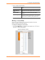
3. Click Submit. Changes are applied immediately to the XPort AR.
Start and Stop Characters
The XPort AR can be configured to start a tunnel when it receives a specific start
character from the serial port. The XPort AR can also be configured to disconnect
upon receiving the stop character.
To configure the start and stop characters mode:
1. Select Tunnel 1 Æ Stop/Start Chars from the navigation menu. The Tunnel 1
Start/Stop Chars window displays.
XPort AR User Guide
34
4: Configuration Using Web Manager
Figure 4-19. Tunnel 1 Start/Stop Chars
2. Enter or modify the following fields:
Start Character
Enter the start character in either ASCII or hexadecimal
notation.
Stop Character
Enter the start character in either ASCII or hexadecimal
notation.
Echo Start Character
Select On to forward (tunnel) the start character.
Echo Stop Character
Select On to forward (tunnel) the stop character.
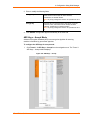
3. Click Submit. Changes are applied immediately to the XPort AR.
Modem Emulation
Configure the modem emulation settings when selecting Modem Emulation as the
Tunnel 1 or Tunnel 2 Connect Mode type.
To configure modem emulation:
1. Select Tunnel 1 Æ Modem Emulation from the navigation menu. The Tunnel 1
Modem Emulation window displays.
Figure 4-20. Tunnel 1 Modem Emulation
XPort AR User Guide
35
4: Configuration Using Web Manager
2. Enter or modify the following fields:
Echo Pluses
Select On to echo “+++” when entering modem command
mode
Echo Commands
Select On to echo the modem commands to the console.
Verbose Response
Codes
Select On to send modem response codes out on the serial
line.
Response Codes
Select the type of response code from either Text or
Numeric.
Connect String
Enter the connect string. This modem initialization string
prepares the modem for communications. It is a customized
string sent with the “CONNECT” modem response code.
3. Click Submit. Changes are applied immediately to the XPort AR.
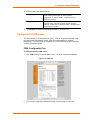
AES Keys – Connect Mode
Advanced Encryption Standard (AES) is an encryption algorithm for securing
sensitive information by government agencies.
To configure the AES keys for connect mode:
1. Click Tunnel 1Æ AES Keys – Connect from the navigation menu. The Tunnel 1
AES Keys – Connect window displays.
Figure 4-21. AES Keys – Connect
XPort AR User Guide
36
4: Configuration Using Web Manager
2. Enter or modify the following fields:
Encrypt Key
Enter the value for each byte. From the pull-down menu,
select the format for the byte as either character,
hexadecimal, or decimal notation.
Note: Any empty trailing bites that are not specified are set to
0.
Decrypt Key
Enter the value for each byte of the decrypt key. From the
pull-down menu, select the format for the byte as either
character, hexadecimal, or decimal notation.
Note: Any empty trailing bites that are not specified are set to
0.
3. Click Submit. Changes are applied immediately to the XPort AR.
AES Keys – Accept Mode
Advanced Encryption Standard (AES) is an encryption algorithm for securing
sensitive information by government agencies.
To configure the AES keys for accept mode:
1. Click Tunnel 1 Æ AES Keys – Accept from the navigation menu. The Tunnel 1
AES Keys – Accept window displays.
Figure 4-22. AES Keys – Accept
XPort AR User Guide
37
4: Configuration Using Web Manager
2. Enter or modify the following fields:
Encrypt Key
Enter the value for each byte. From the pull-down menu,
select the format for the byte as either character,
hexadecimal, or decimal notation. All trailing bytes not
specified are set to 0.
Decrypt Key
Enter the value for each byte of the decrypt key. From the
pull-down menu, select the format for the byte as either
character, hexadecimal, or decimal notation. All trailing bytes
not specified are set to 0.
3. Click Submit. Changes are applied immediately to the XPort AR.
Configurable Pin Manager
The XPort AR has 11 Configurable Pins (CPs). CPs can be grouped together using
the Configurable Pin Manager (CPM). Each CP is associated to an external
hardware pin. CPs can trigger an outside event (such as sending an email message
or starting Command Mode).
CPM: Configurable Pins
To configure the XPort AR’s CPs:
1. Click CPM Æ CPs from the navigation menu. The CPM: CPs window displays.
Figure 4-23. CPM: CPs
2. The Current Configuration table displays the current settings for each CP:
XPort AR User Guide
38
4: Configuration Using Web Manager
Current Configuration
CP
Indicates the Configurable Pin number.
Pin #
Indicates the hardware pin number associated with the CP.
Configured As
Displays the CPs configuration. A CP configured as Input is
set to read input. A CP configured as Output drives data out
of the XPort AR. Peripheral is a setting assigned by the
XPort AR.
State
A value of 1 means asserted. 0 means de-asserted. I
indicates the CP is inverted.
Groups
Indicates the number of groups in which the CP is a member.
Active In Group
A CP can be a member of several groups. However, it may
only be active in one group. This field displays the group in
which the CP is active.
3. To display the CP status of a specific pin, click the CP number under the Current
Configuration table. The CP Status table displays detailed information about the
CP.
CP Status
Name
Displays the CP number.
State
Current enable state of the CP.
Note: Peripheral pins are locked.
Value
Displays the last bit in the CP’s current value.
Bit
Visual display of the 32 bit placeholders for a CP.
I/O
A “+” symbol indicates the CP is asserted (the voltage is high).
A “-“ indicates the CP voltage is low.
Logic
An “I” indicates the CP is inverted.
State
Displays the assertion value of the corresponding bit.
CP#
Displays the CP number.
Groups
Lists the groups in which the CP is a member.
4. To change a CP’s value:
a) Select the CP from the drop-down list.
b) Enter the CP’s value.
c) Click Submit. Changes are applied immediately to the XPort AR.
5. To change a CP’s configuration:
a) Select the CP from the drop-down list.
b) Select the CP’s configuration from the drop-down list.
c) (If necessary) Select the Assert Low checkbox.
d) Click Submit. Changes are applied immediately to the XPort AR.
Note: To modify a CP, all groups in which it is a member must be disabled.
XPort AR User Guide
39
4: Configuration Using Web Manager
CPM: Groups
The CP Groups page allows for the management of CP groups. Create a CP group
and add CPs to it. A group, based on its state, triggers outside events (such as
sending email messages). Only an enabled group can be used as a trigger.
To configure the XPort AR’s CP groups:
1. Click CPM Æ Groups from the navigation menu. The CPM: Groups window
displays.
Figure 4-24. CPM: Groups
2. The Current Configuration table displays the current settings for each CP group:
Current Configuration
Group Name
Displays the CP group’s name.
State
Indicates whether the group is enabled or disabled.
CP Info
Provides CP group information.
3. To display the status of a specific group, click the CP group name under the
Current Configuration table. The Group Status table displays, providing detailed
information about the CP group.
Group Status
Name
Displays the CP Group name.
State
Current enable state of the CP group.
Note: Peripheral pins are locked.
XPort AR User Guide
40
4: Configuration Using Web Manager
Value
Displays the CP group’s current value.
Bit
Visual display of the 32 bit placeholders for a CP.
I/O
A “+” symbol indicates the CP’s bit position is asserted (the
voltage is high). A “-“ indicates the CP voltage is low.
Logic
An “I” indicates the CP is inverted.
State
Displays the assertion value of the corresponding bit.
CP#
Displays the Configurable Pin number and its bit position in
the CP group.
2. To create a CP group:
a) Enter a group name in the Create Group field.
b) Click Submit. Changes are applied immediately to the XPort AR.
3. To delete a CP group:
a) Select the CP group from the Delete Group drop-down list.
b) Click Submit. Changes are applied immediately to the XPort AR.
4. To enable or disable a CP group:
a) Select the CP group from the Set drop-down list.
b) Select the state (Enabled or Disabled) from the drop-down list.
c) Click Submit. Changes are applied immediately to the XPort AR.
5. To set a CP group’s value:
a) Select the CP group from the Set drop-down list.
b) Enter the CP group’s value in the value field.
c) Click Submit. Changes are applied immediately to the XPort AR.
6. To add CP to a CP group:
a) Select the CP from the Add drop-down list.
b) Select the CP group from the drop-down list.
c) Select the CP’s bit location from the bit drop-down menu.
d) Click Submit. Changes are applied immediately to the XPort AR.
7. To delete a CP from a CP group:
a) Select the CP from the Remove drop-down list.
b) Select the CP group from the drop-down list.
c) Click Submit. Changes are applied immediately to the XPort AR.
XPort AR User Guide
41
4: Configuration Using Web Manager
SSH Settings
Secure Shell (SSH) is a protocol used to access a remote computer over an
encrypted channel. It is a protocol for managing the security of data transmission
over the Internet. It provides encryption, authentication, and message integrity
services. Select the SSH link on the left menu bar to display the SSH menu over an
encrypted channel. The sub-menus allow for the configuration of the SSH server
(when the XPort AR acts as the server) and the SSH client (when the XPort AR acts
as the client).
SSH Server’s Host Keys
To configure the SSH server’s host keys:
1. Click SSH Æ Server Host Keys from the navigation menu. The SSH Server:
Host Keys window displays.
Figure 4-25. SSH Server: Host Keys
2. Enter or modify the following fields:
Host Keys
Private Key
Browse and locate the private key. Required when the Public
Key is specified.
Public Key
Browse and locate the public key. Required when the Private
Key is specified
Key Type
Select the key type. DSA is more secure than RSA.
Note: One set of RSA keys and one set of DSA keys are
accepted.
3. Click Submit. Changes are applied immediately to the XPort AR.
XPort AR User Guide
42
4: Configuration Using Web Manager
4. To create new keys, select the following option buttons:
Create New Keys
Key Type
Select RSA or DSA.
Bit Size
Select the size of the key. Large bit keys require more time to
generate.
Note: Certain SSH clients require RSA host keys to be at
least 1024 bits.
5. Click Submit. Changes are applied immediately to the XPort AR.
SSH Server’s Authorized Users
To configure the SSH server’s authorized users:
1. Click SSH Æ Server Authorized Users from the navigation menu. The SSH
Server: Authorized Users window displays.
Figure 4-26. SSH Server: Authorized Users
2. Enter or modify the following fields:
Authorized Users
Username
Enter the username for an authorized user. Required when
the Password is specified.
Password
Enter the password for SSH login to the XPort AR. Required
when the Username is specified.
Public RSA Key
Browse and locate the RSA public key for this authorized
user. This is used for key authentication. When successful,
no password is requested.
Public DSA Key
Browse and locate the DSA public key for this authorized
user. This is used for key authentication. When successful, no
password is requested.
3. Click Submit. Changes are applied immediately to the XPort AR.
XPort AR User Guide
43
4: Configuration Using Web Manager
SSH Client Known Hosts
To configure the SSH client’s known hosts:
1. Click SSH Æ Client Known Hosts from the navigation menu. The SSH Client:
Known Hosts window displays.
Figure 4-27. SSH Client: Known Hosts
2. Enter or modify the following fields:
Server
Enter the hostname or IP address of the remote server
location.
Public RSA Key
Click Browse to locate the public RSA key to use when
authenticating the connection to the server.
Public DSA Key
Click Browse to locate the public DSA key to use when
authenticating the connection to the server.
Note: These fields are not required for communication. They protect
against Man-In-The-Middle (MITM) attacks.
3. In the Current Configuration table, delete currently stored fields as necessary.
4. Click Submit. Changes are applied immediately to the XPort AR.
SSH Client User Configuration
To configure the SSH client’s users:
1. Click SSH Æ SSH Client Users from the navigation menu. The SSH Client:
Users window displays.
XPort AR User Guide
44
4: Configuration Using Web Manager
Figure 4-28. SSH Client: Users
2. Enter or modify the following fields:
Username
Enter the XPort AR’s username for use when connecting to
the server.
Password
Enter the password associated with the username.
Remote Command
Enter the remote command to provide to the server. This
command triggers the desired or appropriate application to
execute. A shell starts by default.
Private Key
Browse and locate the private key to use for authentication
with the remote server.
Public Key
Browse and locate the public key to use for authentication with
the remote server.
Key Type
Select the key type. DSA is more secure than RSA.
3. To create new keys, select the following option buttons:
Create New Keys
Key Type
Select RSA or DSA.
Bit Size
Select the size of the key.
Note: Large bit keys require more time to generate.
4. Click Submit. Changes are applied immediately to the XPort AR.
5. In the Current Configuration table, delete currently stored fields as necessary.
6. Click Submit. Changes are applied immediately to the XPort AR.
XPort AR User Guide
45
4: Configuration Using Web Manager
SSL Settings
Secure Socket Layer (SSL) is a protocol for managing the security of data
transmission over the Internet. It provides encryption, authentication, and message
integrity services. SSL is widely used for secure communication to a web server.
Select the SSL link on the left menu bar to display the SSL menu. The Web
Manager also permits the creation of self-signed certificates. This type of SSL
certificate is a certificate not signed by a valid Certificate Authority (CA).
To configure the XPort AR’s SSL settings:
1. Click SSL from the main menu. The SSL window displays.
Figure 4-29. SSL
2. Enter or modify the following fields:
Upload Certificate
New Certificate
Browse and locate the digital certificate for use in SSL
communications. Required field when configuring the Private
Key.
Private Key
Browse and locate the private key. This private key is a
secret and known only to the certificate’s owner. Required
field when configuring a New Certificate.
XPort AR User Guide
46
4: Configuration Using Web Manager
3. Click Submit. Changes are applied immediately to the XPort AR.
4. To create a new self-signed certificate, enter the following information:
Create New Self-Signed Certificate
Country
Enter the 2-letter country code.
State/Province
Enter the state or province within the country.
Locality
Enter the city within the State/Province.
Organization
The name of the organization owning the certificate.
Organization Unit
The organization’s division (unit) using the certificate.
Contact Name
Enter the Contact Name for the certificate.
Expires
Enter, in mm/dd/yyy format, the certificate’s expiry date.
Bit Size
Select the certificate’s bit size.
Note: Large bit keys require more time to generate.
5. Click Submit. Changes are applied immediately to the XPort AR.
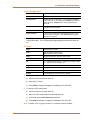
Command Line Interface Settings
Select the CLI link on the left menu bar to display the Command Line Interface
menu.
Figure 4-30. Command Line Interface Statistics
CLI Configuration
To configure the CLI:
1. Click CLI Æ Configuration from the navigation menu. The Command Line
Interface window displays.
XPort AR User Guide
47
4: Configuration Using Web Manager
Figure 4-31. Command Line Interface Configuration
2. Enter or modify the following fields:
Telnet Access
Select On to enable Telnet access. Telnet is enabled by
default.
Telnet Port
Enter the Telnet port to use for Telnet access. The default is
23.
SSH Access
Select On to enable SSH access. SSH is enabled by default.
SSH Port
Enter the SSH port to use for SSH access. The default is 22.
Password
Enter the password for Telnet access.
Enable Password
Enter the password for access to the Command Mode Enable
level. There is no password by default.
3. Click Submit. Changes are applied immediately to the XPort AR.
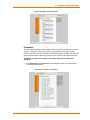
HTTP Settings
Hypertext Transfer Protocol (HTTP) is the transport protocol for communicating
hypertext documents on the Internet. HTTP defines how messages are formatted and
transmitted. It also defines the actions Web servers and browsers should take in
response to different commands.
Select the HTTP link on the left menu bar to display the HTTP menu. The submenus allow for HTTP configuration, HTTP authentication administration, or RSS
configuration.
To view HTTP statistics:
1. Click HTTP Æ Statistics from the navigation menu. The HTTP Statistics window
displays.
XPort AR User Guide
48
4: Configuration Using Web Manager
Figure 4-32. HTTP Statistics
HTTP Configuration
To configure HTTP:
1. Click HTTP Æ HTTP Configuration from the navigation menu. The HTTP
Configuration window opens.
Figure 4-33. HTTP Configuration
XPort AR User Guide
49
4: Configuration Using Web Manager
2. Enter or modify the following fields:
HTTP Server
Select On to enable the HTTP server.
HTTP Port
Enter the port for the HTTP server to use. The default is 80.
HTTPS Port
Enter the port for the HTTPS server to use. The default is
443. The HTTP server only listens on the HTTPS Port when
an SSL certificate is configured.
Max Timeout
Enter the maximum time for the HTTP server to wait when
receiving a request. This prevents Denial-of-Service (DoS)
attacks. The default is 10 seconds.
Max Bytes
Enter the maximum number of bytes the HTTP server accepts
when receiving a request. The default is 32 KB (this prevents
DoS attacks).
Logging
Select On to enable HTTP server logging.
Max Log Entries
Sets the maximum number of HTTP server log entries. Only
the last Max Log Entries are cached and viewable.
Log Format
Set the log format string for the HTTP server. The Log
Format directives are as follows:
%a - remote IP address (could be a proxy)
%b - bytes sent excluding headers
%B - bytes sent excluding headers (0 = '-')
%h - remote host (same as '%a')
%{h}i - header contents from request (h = header string)
%m - request method
%p - ephemeral local port value used for request
%q - query string (prepend with '?' or empty '-')
%t - timestamp HH:MM:SS (same as Apache
'%(%H:%M:%S)t' or '%(%T)t')
%u - remote user (could be bogus for 401 status)
%U - URL path info
%r - first line of request (same as '%m %U%q <version>')
%s - return status
2. Click Submit. Changes are applied immediately to the XPort AR.
HTTP Authentication
To configure HTTP authentication settings:
1. Click HTTP Æ Authentication from the navigation menu. The HTTP
Authentication window opens.
XPort AR User Guide
50
4: Configuration Using Web Manager
Figure 4-34. HTTP Authentication
2. Enter or modify the following fields:
URI
Enter the Uniform Resource Identifier (URI).
Realm
Enter the domain, or realm, used for HTTP. Required with the
URI field.
Auth Type
Select the authentication type. None means no authentication
is necessary. Basic encodes passwords using Base64.
Digest encodes passwords using MD5. SSL means the page
can only be accessed over SSL (no password is required).
SSL/Basic means the page is accessible only over SSL and
encodes passwords using Base64. SSL/Digest means the
page is accessible only over SSL and encodes passwords
using MD5.
Username
Enter the Username used to access the URI.
Password
Enter the Password for the Username.
3. In the Current Configuration table, delete and clear currently stored fields as
necessary.
4. Click Submit. Changes are applied immediately to the XPort AR.
Note: More than one Username per URI is permitted. Click Submit and enter the
next Username as necessary.
HTTP RSS
Rich Site Summary (RSS) is a method of feeding online content to Web users.
Instead of actively searching for XPort AR configuration changes, RSS feeds permit
viewing only relevant and new information regarding changes made to the XPort AR
via an RSS publisher. The RSS feeds are also stored to the filesystem’s cfg_log.txt
file.
XPort AR User Guide
51
4: Configuration Using Web Manager
To configure HTTP RSS settings:
1. Click HTTP Æ RSS from the navigation menu. The HTTP RSS window opens
and displays the current RSS configuration.
Figure 4-35. HTTP RSS
2. Enter or modify the following fields:
RSS Feed
Select On to enable RSS feeds to an RSS publisher.
Persistent
Select On to enable the RSS feed to be written to a file
(cfg_log.txt) and available across reboots.
Max Entries
Sets the maximum number of log entries. Only the last Max
Entries are cached and viewable.
3. In the Current Configuration table, view and clear currently stored fields as
necessary.
4. Click Submit. Changes are applied immediately to the XPort AR.
XML Configuration
The XPort AR allows for the configuration of units using an XML configuration file.
Export a current configuration for use on other XPort ARs or import a saved
configuration file. For more information on using XML, see XML on page 134.
Import System Configuration
To import and apply an XML configuration:
1. Click XML Æ Import from the navigation menu. The XML: Import System
Configuration window opens.
XPort AR User Guide
52
4: Configuration Using Web Manager
Figure 4-36. Import System Configuration
2. Use one of the following methods to import the XCR file:
a) To import an XCR file from the filesystem, select Import XCR file from the
filesystem and enter the filename on the XPort AR containing the file to
import.
b) To import an external file, select Import external XCR file and click Browse.
Locate the file in the Choose File window.
3. (Optional) Enter the filter to apply in the Filter field. This selects the groups to
import. The format of the input is:
<g>:<i>;<g>:<i>; …
Each group name (<g>) is followed by a colon (:) and the instance value (<i>).
Each set of these ends with a semi-colon (;). If a group has no instance, specify
only the group name (<g>).
4. Select from the list of checkboxes the groups to import. If no groups are
selected, all the groups will be imported.
5. Click Import. The settings for the groups selected are applied to the XPort AR.
XPort AR User Guide
53
4: Configuration Using Web Manager
Export System Configuration
To export and store an XPort AR’s configuration:
1. Click XML Æ Export from the navigation menu. The XML: Export System
Configuration window opens.
Figure 4-37. Export System Configuration
2. Use one of the following methods to export the XCR file:
a) To view the XCR data (without storing it), select Export ECR data to
browser.
b) To export to a file on the XPort AR filesystem, select Export XCR data to
the filesystem. In the text box, enter the name for the file. The system will
create the file and store it in the root directory of the XPort AR.
3. Select from the list of checkboxes the groups to export. If no groups are
selected, all the groups will be exported.
XPort AR User Guide
54
4: Configuration Using Web Manager
4. Click Export. The groups display if exporting the data to the browser. If
exporting to the filesystem, the files are stored on the filesystem. (To view these
files or store them elsewhere, see Filesystem Configuration on page 56.)
Email Configuration
The XPort AR allows for the configuration of four email alerts relating to the
Configuration Pins (CPs). Select the Email link on the left menu bar to display the
Email menu and statistics.
Note: The following section describes the steps to configure Email 1; these
steps also apply to Email 2, Email 3, and Email 4 menu options.
Figure 4-38. Email Statistics
To configure XPort AR’s email settings:
1. Click Email Æ Configuration from the navigation menu. The Email
Configuration window opens and displays the current Email configuration.
Figure 4-39. Email Configuration
XPort AR User Guide
55
4: Configuration Using Web Manager
2. Enter or modify the following fields:
To
Enter the email address to which the email alerts will be sent.
CC
Enter the email address to which the email alerts will be
CC’ed.
From
Enter the email address to list in the From field of the email
alert.
Reply-To
Enter the email address to list in the Reply-To field of the
email alert.
Subject
Enter the subject for the email alert.
File
Enter the path of the file to send with the email alert. This file
displays within the message body of the email.
Overriding Domain
Enter the domain name to override the current domain name
in EHLO (Extended Hello).
Server Port
Enter the SMTP server port number. The default is a random
port number.
Local Port
Enter the local port to use for email alerts.
Priority
Select the priority level for the email alert.
CP Send
Configure this field to send an email based on a CP Group
trigger. An email is sent when the specified Value matches
the current Group’s value.
3. In the Current Configuration table, delete currently stored fields as necessary.
4. Click Submit. Changes are applied immediately to the XPort AR.
Filesystem Configuration
The XPort AR uses a flash filesystem to store files. Use the Filesystem option to
view current file diagnostics or modify files.
Figure 4-40. Filesystem
XPort AR User Guide
56
4: Configuration Using Web Manager
To compact or format the XPort AR’s filesystem:
1. Click Filesystem from the navigation menu. The Filesystem window opens and
displays the current filesystem statistics and usage.
2. To compact the files, click Compact.
Note: Data can be lost if power is cycled when compacting the
filesystem.
3. To reformat the filesystem, click Format.
Note: All files and configuration settings on the filesystem are destroyed
upon formatting, including Web Manager files. Back up all files as
necessary. Upon formatting, the current configuration is lost.
To browse the XPort AR’s filesystem:
1. Click Filesystem Æ Browse from the navigation menu. The Filesystem Browser
window opens and displays the current filesystem configuration.
Figure 4-41. Filesystem Browser
2. Click on a filename to view the contents.
XPort AR User Guide
57
4: Configuration Using Web Manager
3. Click the X next to a filename to delete the file or directory. A directory can only
be deleted if it is empty.
4. Enter or modify the following fields:
Note: Changes apply to the current directory view. To make changes within
other folders, click on the folder or directory and then enter the parameters in
the fields listed below.
Create
File
Enter a filename and click Create. The XPort AR creates the
empty file (0 bytes) and stores it in the current directory.
Directory
Enter a folder name and click Create. The XPort AR creates
the folder and stores it in the current directory.
Upload File
Browse
Click Browse and locate the file to upload to the current
filesystem directory. Click Upload to complete the process.
Copy File
Source
Enter the filename to copy.
Destination
Enter the folder where the Source file will be copied. Click
Copy to complete the process.
Note: The Source and Destination filenames can be
different.
Move
Source
Enter the filename to move.
Destination
Enter the folder into which the Source file will be moved.
Click Move to complete the process.
Note: When the Source and Destination filenames are
different, the file and folder are renamed.
TFTP
Action
Select Get or Put. Choose Get to receive a file. Choose Put
to send a file.
Mode
Select ASCII or Binary.
Local File
Enter the name of the file to send to the remote location (Put)
or to store locally (Get).
Remote File
Enter the name of the file on the remote location to store
externally (Put) or to store locally (Get).
Host
Enter the IP address or hostname of the remote location.
Port
Enter the port number for TFTP communication. Click
Transfer to complete the file transfer. The default is port 69.
XPort AR User Guide
58
4: Configuration Using Web Manager
Diagnostics Configuration
The XPort AR has several tools for diagnostics and statistics. Select the
Diagnostics link on the left menu bar to display the Diagnostics menu. The submenus allow for the configuration or viewing of MIB2 statistics, IP socket information,
ping, traceroute, DNS lookup, memory, buffer pools, processes, and hardware.
MIB2 Statistics
To view XPort AR’s MIB2 statistics:
1. Click Diagnostics Æ MIB2 Statistics from the navigation menu. The MIB2
Network Statistics window opens.
Figure 4-42. MIB2 Network Statistics
2. Click on any of the available links to open the corresponding table and statistics.
For more information, refer to the following Requests for Comments (RFCs):
RFC 1213
Original MIB2 definitions.
RFC 2011
Updated definitions for IP and ICMP.
RFC 2012
Updated definitions for TCP.
RFC 2013
Updated definitions for UDP.
RFC 2096
Definitions for IP forwarding.
IP Sockets
To display open network sockets on the XPort AR:
1. Click Diagnostics Æ IP Sockets from the navigation menu. The IP Sockets
window opens and displays all of the open network sockets on the XPort AR.
XPort AR User Guide
59
4: Configuration Using Web Manager
Figure 4-43. IP Sockets
Ping
To ping a remote device or computer:
2. Click Diagnostics Æ Ping from the navigation menu. The Diagnostics: Ping
window opens.
Figure 4-44. Diagnostics: Ping
3. Enter or modify the following fields:
Host
Enter the IP address for the XPort AR to ping.
Count
Enter the number of ping packets XPort AR should attempt to
send to the Host. The default is 3.
Timeout
Enter the time, in seconds, for the XPort AR to wait for a
response from the host before timing out. The default is 5
seconds.
4. Click Submit. The results of the ping display in the window.
XPort AR User Guide
60
4: Configuration Using Web Manager
Traceroute
To use traceroute from the XPort AR:
1. Click Diagnostics Æ Traceroute from the navigation menu. The Diagnostics:
Traceroute window opens.
Figure 4-45. Diagnostics: Traceroute
2. Enter or modify the following fields:
Traceroute
Enter the IP address or DNS hostname. This address is used
to show the path between it and the XPort AR when issuing
the traceroute command.
3. Click Submit. The results of the traceroute display in the window.
DNS Lookup
To use forward or reverse DNS lookup:
1. Click Diagnostics Æ DNS Lookup from the navigation menu. The Diagnostics:
DNS Lookup window opens.
Figure 4-46. Diagnostics: DNS Lookup
XPort AR User Guide
61
4: Configuration Using Web Manager
2. Enter or modify the following field:
Lookup
Enter an IP address for reverse lookup to locate the hostname
for that IP address. Enter a hostname for forward lookup to
locate the corresponding IP address. Enter a domain name
(prefixed with “@”) to look up the Mail Exchange (MX) record
IP address.
3. Click Submit. The results of the lookup display in the window.
Memory
To display memory statistics for the XPort AR:
1. Click Diagnostics Æ Memory from the navigation menu. The Diagnostics:
Memory window displays.
Figure 4-47. Diagnostics: Memory
Buffer Pools
Several parts of the XPort AR system use private buffer pools to ensure deterministic
memory management.
To display the XPort AR’s buffer pools:
1. Click Diagnostics Æ Processes from the navigation menu. The Diagnostics:
Buffer Pools window opens.
XPort AR User Guide
62
4: Configuration Using Web Manager
Figure 4-48. Diagnostics: Buffer Pools
Processes
The XPort AR Processes window displays all the processes currently running on the
system. It displays the Process ID (PID), the percentage of total CPU cycles a
process used within the last 2 seconds, the total stack space available, the maximum
amount of stack space used by the process since it started, and the process name.
To display the processes running on the XPort AR and their associated
statistics:
1. Click Diagnostics Æ Processes from the navigation menu. The Diagnostics:
Processes window opens.
Figure 4-49. Diagnostics: Processes
XPort AR User Guide
63
4: Configuration Using Web Manager
Note: The Adobe SVG plug-in is required to view the CPU Load Graph.
Hardware
The Hardware window displays basic hardware information and allows for the
modification of the CPU speed.
To display the XPort AR’s hardware diagnostics:
1. Click Diagnostics Æ Hardware from the navigation menu. The Diagnostics:
Hardware window opens and displays current the current hardware configuration.
Figure 4-50. Diagnostics: Hardware
2. Enter or modify the following field:
CPU Speed
Enter the XPort AR’s CPU speed. Accepted values are
between 25 and 120 MHz.
4. Click Submit. The CPU speed is updated immediately (no reboot required).
System Configuration
The XPort AR System window allows for rebooting the device, restoring factory
defaults, uploading new firmware, configuring the short and long name, and viewing
the current system configuration.
XPort AR User Guide
64
4: Configuration Using Web Manager
Figure 4-51. System
To configure the XPort AR’s system settings:
1. Click System from the navigation menu. The System window opens.
2. Configure the XPort AR’s system using the following fields:
Reboot Device
Click Reboot to reboot the XPort AR. The system refreshes
and redirects the browser to the XPort AR’s home page.
Restore Factory Defaults
Click Factory Defaults to restore the XPort AR to the original
factory settings. All configurations will be lost. The XPort AR
automatically reboots upon setting back to the defaults.
Upload New Firmware
Click Browse to locate the firmware file location. Click
Upload to install the firmware on the XPort AR. The device
automatically reboots upon the installation of new firmware.
Name
Enter a new Short Name and a Long Name (if necessary).
The Short Name is a maximum of 8 characters. Changes
take place upon the next reboot.
XPort AR User Guide
65
5: Configuration Using Telnet or Serial Port
Configure the XPort AR so that it can communicate on a network with your serial
device. For example, set the way the unit responds to serial and network traffic, how
it handles serial packets, and when to start or close a connection.
As an alternative to using Web Manager, configure the XPort AR using a series of
prompts referred to as Command Mode, accessed through a Telnet or a serial port
connection.
The configuration may be changed at any time. Changes are applied immediately to
the XPort AR (except for network configurations, which require a reboot).
This chapter provides instructions on using Command Mode and detailed
explanations of the available commands.
Accessing Command Mode
Using Telnet
To configure the unit over the network, establish a Telnet connection.
Note: As an alternative, establish a Telnet connection by clicking the Telnet
tab in the DeviceInstaller. See Using DeviceInstaller on page 15.
1. From the Windows Start menu, click Run and type the following command,
where x.x.x.x is the IP address:
telnet x.x.x.x
2. Click OK. Upon connection, enter “!” multiple times until one character appears
on screen.
3. Enter “xyz” to enter Command Mode.
Using the Serial Port
For local configuration, connect a terminal or a PC running a terminal emulation
program to the unit’s serial port. Configure the terminal (or emulation) for 9600 baud,
8-bit, no parity, 1 stop bit, and no flow control.
1. Cycle the unit’s power (power off and back on). After power-up, the self-test
begins and the diagnostic and status LEDs start blinking.
2. Click OK. Upon connection, enter “!” multiple times until one character appears
on screen.
3. Enter “xyz” to enter Command Mode.
XPort AR User Guide
66
5: Configuration Using Telnet or Serial Port
Navigating the Command Line Interface
Commands at the root level (top level) of the CLI do not affect current configuration
settings. Commands within the Enable menu (and its sub-menus) modify the XPort
AR’s configuration.
Items within < > (e.g. <string>) are required parameters.
To view acceptable commands enter “?”.
To move to a sub-level and traverse the tree of commands, enter each sub-command
only in its parent command prompt. For example, to access the Tunnel1 level within
the Enable level (which is below the root level), enter:
root>enable
root(enable)#tunnel1
To exit and return to the menu one level higher, type exit.
The following key combinations are permitted when configuring the XPort AR from
the CLI:
Ctrl + a: place cursor at the beginning of line
Ctrl + b: backspace one character
Ctrl + d: delete one character
Ctrl + e: place cursor at the end of the line
Ctrl + f: move cursor forward one character
Ctrl + k: delete everything to the end of the line
Ctrl + l: redraw the command line
Ctrl + n: display the next line in the history
Ctrl + p: display the previous line in the history
Ctrl + u: delete entire line and place cursor at start of prompt
Ctrl + w: delete one word back in line
Esc + b: move cursor back one word
Esc + f: move cursor forward one word
Note: The XPort AR CLI also supports tab completion.
To view the current configuration at any level:
Type show. The configuration for that menu level displays.
To view the list of commands available at the current menu level:
At the command prompt, enter ?. The list of current commands displays.
To return to the next level up in the menu hierarchy:
At the command prompt, type exit. The prompt for the parent menu displays.
To view the available commands and their explanation:
At the command prompt, type *. The list of commands for that menu level and
their description displays.
XPort AR User Guide
67
5: Configuration Using Telnet or Serial Port
XPort AR CLI Level Hierarchy
XPort AR User Guide
68
5: Configuration Using Telnet or Serial Port
Root Configuration Menu
Top level root commands do not alter the configuration of the XPort AR.
Clrscrn
Clears the screen.
Enable
Displays the Enable level prompt. Within this menu, changes can be written to the
XPort AR. For the list of Enable prompts, see Enable Menu on page 70.
Exit
Exit from the system.
Ping <host>
Pings the host destination 5 times with a 5 second timeout.
Ping <host> <count>
Pings the host destination the specified number of times (count) with a 5 second
timeout.
Ping <host> <count> <timeout>
Pings the string destination the specified number of times (count) with a specified
timeout (in seconds).
Show history
Shows the set of commands inputted from the moment user was brought back up to
this menu. Entering a sub-menu, and then returning to this menu displays only the
commands inputted since re-entering this command set.
Show XPort
Shows current XPort AR settings.
Trace route <host>
Determines the path taken from a computer to a specified destination. Enter the
destination IP address.
XPort AR User Guide
69
5: Configuration Using Telnet or Serial Port
Enable Menu
The following sections describe the configurable parameters within the Enable
configuration menu.
Auto show interfaces
Displays interface statistics.
Auto show processes
Continuously displays thread runtime information.
Chem
Change from the Enable menu to the Configure Email 1 (Chem) sub-menu. For the
list of Chem prompts, see Chem Menu on page 74.
Chem 1
Change from the Enable menu to the Configure Email 1 (Chem) sub-menu. For the
list of Chem prompts, see Chem Menu on page 74.
Chem 2
Change from the Enable menu to the Configure Email 2 (Chem) sub-menu. For the
list of Chem prompts, see Chem Menu on page 74.
Chem 3
Change from the Enable menu to the Configure Email 3 (Chem) sub-menu. For the
list of Chem prompts, see Chem Menu on page 74.
Chem 4
Change from the Enable menu to the Configure Email 4 (Chem) sub-menu. For the
list of Chem prompts, see Chem Menu on page 74.
Clear interface counters
Sets to zero the interface session counters.
Clear line <number>
Use the show sessions command to view the active command mode sessions on
the XPort AR. Each session is assigned a number. Use the clear line command
to end a specific command mode session.
XPort AR User Guide
70
5: Configuration Using Telnet or Serial Port
Clear query port counters
Sets to zero the Query Port counters.
Clear ssh <session>
Ends an active SSH session on the XPort AR.
Clear telnet <session>
Ends an active Telnet session on the XPort AR.
Configure
Displays the Configuration level menu. For the list of commands within this menu,
see Configure Menu on page 78.
CPM
Displays the Configuration Pin Manager (CPM) level menu. For the list of commands
within this menu, see CPM Menu on page 91.
Device
Displays the Device level menu. For the list of commands within this menu, see
Device Menu on page 94.
Disable
Exits current menu level and returns to main root level menu. For the list of
commands within the root level menu, see Root Configuration Menu on page 68.
Exit
Exit from the system.
Filesystem
Displays the Filesystem level menu. For the list of commands within this menu, see
Filesystem Menu on page 96.
Line1
Displays the Line 1 menu for serial port 1 configuration. For more information on
serial port configuration, see Line Menu on page 99.
Line2
Displays the Line 1 menu for serial port 2 configuration. For more information on
serial port configuration, see Line Menu on page 99.
XPort AR User Guide
71
5: Configuration Using Telnet or Serial Port
Line3
Displays the Line 3 menu for serial port 3 configuration. For more information on
serial port configuration, see Line Menu on page 99.
No clear interfaces counters
Reverts the interface counters to the last aggregate value.
No clear query port counters
Reverts the query port counters to the last aggregate value.
Nslookup
Look up host information for the given host name.
Nslookup <host>
Display host information for a specified host name.
Ping <host>
Pings the host destination 5 times with a 5 second timeout.
Ping <host> <count>
Pings the host destination the specified number (count) of times with a 5 second
timeout.
Ping <host> <count> <timeout>
Pings the host destination the specified number (count) of times with a specified
timeout (in seconds).
Reload
Reboots the XPort AR and reloads the configuration from Flash memory.
Reload factory defaults
Resets the XPort AR configuration to the default settings.
Show arp
Displays the ARP table
XPort AR User Guide
72
5: Configuration Using Telnet or Serial Port
Show history
Displays previously entered commands.
Show hosts
Displays the domain settings.
Show interfaces
Displays network interface statistics.
Show ip sockets
Displays TCP and UDP state information and their associated ports.
Show processes
Displays thread runtime information. This command shows the list of running
processes. The stack is the number of bytes used and the total stack size.
Show query port
Displays statistics and information on the query port.
Show sessions
Displays active Telnet and SSH sessions on the XPort AR.
Show XPort
Displays the XPort AR’s configuration.
Trace route <host>
Determines the path taken from a computer to a specified destination. Enter the
destination IP address.
Tunnel1
Displays the Tunnel 1 menu for tunneling configuration. For more information on
tunnel configuration, see Tunnel Menu on page 107.
Tunnel2
Displays the Tunnel 1 menu for tunneling configuration. For more information on
tunnel configuration, see Tunnel Menu on page 107.
XPort AR User Guide
73
5: Configuration Using Telnet or Serial Port
Write
Store and apply current configuration into permanent memory.
Xcr dump
Display the XML configuration to the console. For more information on XML, see
XML on page 134.
Xcr dump <group list>
Display a specified XML configuration to the console. Separate groups with a
comma. Specify group instances (if they exist) with a colon. For example:
> xcr dump line:1, line:2
Enclose groups with a white space in the name with double quotation marks. For
more information on XML, see XML on page 134
Xcr export <file>
Save the current XPort AR’s configuration to a file. Specify the name for the file; the
XPort AR saves it in its root directory. For more information on XML, see XML on
page 134.
Xcr export <file> <group list>
Save a specified XML configuration to a file. Specify the group name and the name
for the file; the XPort AR saves it in its root directory. For more information on XML,
see XML on page 134.
Xcr import <file>
Import an XML configuration onto the XPort AR. For more information on XML, see
XML on page 134.
Xcr import <file> <group list>
Import a specific XML configuration onto the XPort AR. Specify the group and
filename. For more information on XML, see XML on page 134.
Chem Menu
The following sections describe the configurable parameters within the Chem 1,
Chem 2, Chem 3, and Chem 4 configuration menus. These commands configure
email alert settings.
Auto show statistics
Continuously display email statistics.
XPort AR User Guide
74
5: Configuration Using Telnet or Serial Port
Cc <email address>
Enter the email address to which the alert email is CC’ed. Separate multiple
addresses with a semi-colon.
Chem 2
Displays the Chem 2 menu for configuration.
Chem 3
Displays the Chem 3 menu for configuration.
Chem 4
Displays the Chem 4 menu for configuration.
Clear log
Clears all entries from the mail log.
Clear mail counters
Set to zero the mail counters.
CP send <cp group> <value>
Specify a CP group and its value to trigger an email.
Exit
Exits the Chem menu and returns to the Enable menu (see Enable Menu on page
70).
File <file>
Set the path of the file to use as the email’s message body.
From <email address>
Enter email address to display in the “From” heading of the email.
Local port <number>
Set local port number for the XPort AR to use when sending the email message.
Local port <random>
Set local port setting to random to allow the XPort AR to choose the local port.
XPort AR User Guide
75
5: Configuration Using Telnet or Serial Port
No cc
Clears the CC field in the email.
No clear mail counters
Reverts the mail counters to the last aggregate value.
No cp send
Disable the CP trigger used to send the email.
No file
Removes the file used for the body of the email.
No from
Clears the “From” heading line in the email.
No overriding domain
Removes the overriding domain name option.
No replyto
Clears the Reply-To field in the email.
No subject
Clears the email’s Subject field.
No to
Clears the email’s To address field.
Priority high
Sets the email priority level to high. Displays as high priority if recipient’s email
supports email priority settings. Corresponds to X-Priority level 2.
Priority low
Sets the email priority level to low. Displays as low priority if recipient’s email
supports email priority settings. Corresponds to X-Priority level 4.
Priority normal
Sets the email priority level to normal. Corresponds to X-Priority level 3.
XPort AR User Guide
76
5: Configuration Using Telnet or Serial Port
Priority urgent
Sets the email priority level to urgent. Displays as urgent priority if recipient’s email
supports email priority settings. Corresponds to X-Priority level 1.
Priority very low
Sets the email priority level to very low. Displays as very low priority if recipient’s
email supports email priority settings. Corresponds to X-Priority level 5.
Replyto <email address>
Enter the Reply-To email address. The recipient’s email response is sent to this
address.
Send
Sends the SMTP email.
Note: Both the To and ReplyTo fields must be configured.
Server port <number>
Enter the SMTP server port.
Show
Displays the email configuration settings.
Show log
Displays the email log and results of email transmissions.
Show statistics
Displays number of successful, unsuccessful, and in-transit emails.
Subject <string>
Enter the subject for the email. Spaces are not accepted.
To <email address>
Enter the email address to which the email alert is sent. Separate multiple addresses
with a semi-colon.
Write
Writes the current configuration to permanent storage.
XPort AR User Guide
77
5: Configuration Using Telnet or Serial Port
Configure Menu
The following sections describe the configurable parameters within the Configure
menu.
Arp <ip address> <mac address>
Address Resolution Protocol (ARP) maps an IP address to a device’s MAC address.
The arp command adds an entry to the ARP table.
Auto show icmp
Continuously displays ICMP state and statistics.
Auto show ip
Continuously displays IP statistics.
Auto show tcp
Continuously displays TCP statistics
Auto show udp
Continuously displays UDP statistics
Clear arp-cache
Removes all entries from the ARP table.
Clear ftp counters
Sets the FTP counters to zero.
Clear host <host>
Remove a specified entry from the DNS cache.
Clear http counters
Set the HTTP counters to zero.
Clear icmp counters
Sets the Internet Control Message Protocol (ICMP) counters to zero
XPort AR User Guide
78
5: Configuration Using Telnet or Serial Port
Clear ip counters
Set the IP counters to zero.
Clear ip ssh counters
Set the SSH counters to zero.
Clear ip telnet counters
Set the Telnet counters to zero.
Clear rss
Clears the RSS feed data.
Clear ssh
End an active SSH session on the XPort AR.
Clear tcp counters
Set to zero the TCP counters.
Clear telnet
End an active Telnet session on the XPort AR.
Clear tftp counters
Sets the TFTP counters to zero.
Clear udp counters
Set the UDP counters to zero.
Clrscrn
Clears the screen.
Enable password
Set the password for the Enable-level menu.
Exit
Exit the Configure menu and returns to the Enable menu (see Enable Menu on page
70).
XPort AR User Guide
79
5: Configuration Using Telnet or Serial Port
Hostname <string>
Set the system hostname.
If 1
Display the Interface 1 menu. For more information on serial port configuration, see
Interface 1 Level Menu on page 88.
Ip domain name <string>
Set the default domain name on the XPort AR.
Ip ftp enable
Enable the FTP server.
Ip ftp password <string>
Set the administrative password for the FTP server.
Ip ftp username <string>
Set the administrative username for the FTP server
IP http auth <uri> <realm>
Create a new HTTP server authentication directive.
IP http auth type <uri> basic
Set an HTTP server authentication directive to the Basic Access Authentication
scheme. This directive may not be secured (unless used with an external secure
system) since the username and password are passed unencrypted over the
network.
IP http auth type <uri> digest
Set an HTTP server authentication directive to the Digest Access Authentication
scheme. This directive is more secure than the Basic Access Authentication scheme
because the password is not sent unencrypted over the network.
IP http auth type <uri> none
Set the authentication type for an HTTP server authentication directive to none.
IP http auth type <uri> ssl
Set the authentication type for an HTTP server authentication directive to SSL.
XPort AR User Guide
80
5: Configuration Using Telnet or Serial Port
IP http auth type <uri> ssl-basic
Set the authentication type for an HTTP server authentication directive to SSL-Basic.
IP http auth type <uri> ssl-digest
Set the authentication type for an HTTP server authentication directive to SSLDigest.
IP http auth user <uri> <user> <password>
Create or modify a user for an HTTP server authentication directive.
IP http log
Enable HTTP server logging.
IP http log entries <number>
Set the maximum number of HTTP server log entries.
IP http log format <string>
Set the log format for the HTTP server.
IP http max bytes <bytes>
Set the maximum number of bytes the HTTP server accepts when receiving a
request.
IP http max timeout <seconds>
Set the maximum timeout the HTTP server waits when receiving a request.
IP http port <number>
Set the port number. The HHTP server uses this port number when attempting a
connection.
IP http server
Enable HTTP server.
IP http ssl port <number>
Set the SSL port number for use with the HHTP server.
XPort AR User Guide
81
5: Configuration Using Telnet or Serial Port
IP icmp enable
Allow the transmission and retrieval of Internet Control Message Protocol (ICMP)
packets.
Ip name-server <ip address>
Set the primary DNS server.
Ip name-server <ip address> <ip address>
Set the primary and secondary DNS servers.
Ip ssh enable
Enable the SSH server.
Ip ssh port <number>
Set the local port for SSH that the server uses.
Ip tcp resets enable
Sends TCP RSTs upon connection to unused ports. TCP contains six control bits,
with one or more defined in each packet. RST is one of the control bits. The RST bit
is responsible for telling the receiving TCP stack to immediately end a connection.
Sending this flag poses a security risk.
Ip telnet enable
Enable and start the Telnet server.
Ip telnet port <number>
Set the Telnet port that the server uses.
Ip tftp allow file creation
Enable the automatic creation of files by the TFTP server.
Ip tftp enable
Enable the TFTP server.
No arp
Clear the ARP table.
XPort AR User Guide
82
5: Configuration Using Telnet or Serial Port
No clear ftp counters
Revert the FTP counters to the last aggregate value.
No clear ip ssh counters
Revert the IP SSH counters to the last aggregate value.
No clear ip telnet counters
Reverts the IP Telnet counters to the last aggregate value.
No clear tcp counters
Revert the TCP counters to the last aggregate value.
No clear tftp counters
Revert the TFTP counters to the last aggregate value.
No clear udp counters
Revert the UDP counters to the last aggregate value.
No ip domain name
Remove the IP domain name entered (difference
No ip ftp enable
Disable the IP FTP.
No ip ftp password
Remove the FTP password
No ip ftp username
Remove the FTP username.
No ip http auth <uri>
Deletes an existing HTTP server authentication directive.
No ip http auth user <uri> <user>
Deletes an existing user for the specified HTTP server’s authentication directive.
XPort AR User Guide
83
5: Configuration Using Telnet or Serial Port
No ip http auth log
Disables HTTP server logging.
No ip http auth log format
Removes the log format string for the HTTP server.
No ip http server
Disables the HTTP server.
No ip icmp enable
Prevents the sending or retrieval of ICMP packets.
No ip name-server
Remove the name server.
No ip ssh enable
Disables and stops the SSH server.
No ip tcp resets enable
Prohibits TCP RSTs from sending on connect to unused ports.
No ip telnet enable
Disables the Telnet server.
No ip tftp allow file creation
Disables file creation via TFTP.
No ip tftp enable
Disables the TFTP server.
No password
Removes the root level password.
No query-port enable
Disable the query port.
XPort AR User Guide
84
5: Configuration Using Telnet or Serial Port
No rss enable
Disables the RSS feed.
No rss persistent
Disables RSS feed data persistence.
No snmp-server community ro
Remove the SNMP read-only server community string.
No snmp-server community rw
Remove the SNMP read/write server community string
No snmp-server contact
Remove the SNMP server contact.
No snmp-server description
Clear the SNMP server description.
No snmp-server enable
Disable the SNMP server.
No snmp-server enable traps
Disables SNMP server traps.
No snmp-server host <ip address>
Delete the SNMP server host.
No snmp-server host <ip address> <ip address>
Delete the SNMP server host.
No snmp-server location
Clear the SNMP server location.
No snmp-server name
Clear the SNMP server name.
XPort AR User Guide
85
5: Configuration Using Telnet or Serial Port
Password
Set the new password. Prompts for a password then requests password verification.
Password <string>
Enter the password on one line.
Ppp 1
Display the PPP menu for serial port 1. For more information on PPP configuration,
see PPP Menu on page 91.
Ppp 2
Display the PPP menu for serial port 2. For more information on PPP configuration,
see PPP Menu on page 91.
Query-port enable
Enable the query port.
Show ftp
Display the FTP configuration and statistics.
Show history
Display previously-entered commands.
Show http
Show the HTTP server settings.
Show http auth
Display the HTTP server authentication settings.
Show http log
Show the HTTP server log.
Show http statistics
Show the HTTP server settings.
Show icmp
Display ICMP state and statistics.
XPort AR User Guide
86
5: Configuration Using Telnet or Serial Port
Show ip
Show IP statistics.
Show rss
Show the RSS feed settings.
Show snmp-server
Display SNMP server settings.
Show ssh
Display IP SSH configuration.
Show telnet
Display Telnet configuration.
Show tftp
Display TFTP settings and statistics.
Show udp
Display UDP settings and statistics
Snmp-server community <string> ro
Set the read-only SNMP server community.
Snmp-server community <string> rw
Set the read-write community within the SNMP server.
Snmp-server contact <string>
Set the SNMP system contact information.
Snmp-server description <string>
Enter description for SNMP server.
Snmp-server enable
Enable the SNMP server.
XPort AR User Guide
87
5: Configuration Using Telnet or Serial Port
Snmp-server enable traps
Enable traps on the SNMP server.
Snmp-server host <ip address>
Set the primary SNMP trap host.
Snmp-server host <ip address> <ip address>
Set the primary and secondary SNMP trap hosts.
Snmp-server location <string>
Set the SNMP system location.
Snmp-server name <string>
Set the SNMP system name.
Write
Store and apply current configuration into permanent memory.
Interface 1 Level Menu
The following sections describe the configurable parameters within the Interface (IF
1) configuration menu.
Arp timeout <number>
Set ARP cache timeout.
Bootp
Enable BOOTP.
Clear host <string>
Removes an entry from the DNS cache.
Clrscrn
Clears the screen.
Dhcp
Enable DHCP.
XPort AR User Guide
88
5: Configuration Using Telnet or Serial Port
Dhcp renew
Force DHCP to renew.
Exit
Exit the Interface menu and returns to the Enable menu (see Enable Menu on page
70).
IP address <ip address/bits>
Set the IP address and netmask. Enter the netmask in CIDR notation.
IP address <ip address>
Set the IP address.
IP address <ip address> <ip address>
Set the IP address and netmask. Enter the netmask in dotted notation.
IP address filter <ip address> <ip address>
Add a filter to the IP filter table.
IP default-gateway <ip address>
Set the IP address for the default gateway.
Mac-address <mac address>
Change the MAC address of the device.
No bootp
Disable BOOTP.
No dhcp
Disable DHCP.
No ip address
Remove the IP address.
No ip address filter <ip address> <ip address>
Remove a specified filter from the IP filter table.
XPort AR User Guide
89
5: Configuration Using Telnet or Serial Port
No ip default-gateway
Remove the default gateway.
Show
Show interface settings.
Show history
Display previously-entered commands.
Show ip address filter
Display the IP filter table.
Speed 10
Set the Ethernet link to 10 Mbps (duplex is unchanged).
Speed 10 full
Set the Ethernet link to 10M bps (full-duplex).
Speed 10 half
Set the Ethernet link to 10 Mbps (half-duplex).
Speed 100
Set the Ethernet link to 100 Mbps (duplex is unchanged).
Speed 100 full
Set the Ethernet link to 100 Mbps (full-duplex).
Speed 100 half
Set the Ethernet link to 100 Mbps (half-duplex).
Speed auto
Set the Ethernet link to auto-negotiation.
Write
Store and apply current configuration into permanent memory.
XPort AR User Guide
90
5: Configuration Using Telnet or Serial Port
PPP Menu
The following section describes the configurable parameters within the Point-to-Point
Protocol (PPP) configuration menu. For more information on PPP, see Point-to-Point
Protocol (PPP) on page 119.
Note: The following section describes the parameters within the PPP 1 and
PPP 2 menus.
Exit
Exit the CPM menu and return to the Enable menu (see Enable Menu on page 70).
Ip address <ip address> <netmask>
Sets the local IP address and netmask.
No ip address
Removes the local IP address.
No peer default ip address
Removes the configured peer IP address.
No ppp authentication
Removes PPP authentication.
No ppp enable
Disables PPP.
No username
Removes the PPP authentication username and password.
Peer default ip address <ip address>
Sets the peer IP address.
Ppp authentication chap
Enables the Challenge Handshake Authentication Protocol (CHAP).
Ppp authentication pap
Enables the Password Authentication Protocol (PAP).
XPort AR User Guide
91
5: Configuration Using Telnet or Serial Port
Ppp enable
Enables PPP.
Show
Displays the current PPP configuration.
Username <username> password <password>
Sets the PPP authentication username and password.
Write
Store and apply current configuration into permanent memory.
CPM Menu
The following section describes the configurable parameters within the CPM
configuration menu. For more information on the CPM, see Configuration Pin
Manager on page 131.
Add <cp> to <group>
Add a specified CP to a specified group.
Add <cp> to <group> <bit>
Add a CP to specified group at bit specified bit position.
Clrscrn
Clears the screen.
Create <group>
Creates a Configurable Pin (CP) group. The <string> is the name of the CP group.
Delete <group>
Remove a CP group and reset all CPs to inputs.
Delete <cp> from <group>
Remove a specified CP from a specified group and set it as input.
XPort AR User Guide
92
5: Configuration Using Telnet or Serial Port
Disable <group>
Disable a group and make all CPs available.
Enable <group>
Enable a disabled CP group.
Exit
Exit the CPM menu and return to the Enable menu (see Enable Menu on page 70).
Get <group>
Display the value of a specified CP group.
Set <group> <value>
Assign a value to a specified group.
Set <cp> as input
Configure a CP as an assert high input.
Set <cp> as input assert low
Configure a CP as an assert low input.
Set <cp> as output
Configure a CP as an assert high output.
Set <cp> as output assert low
Configure a CP as an assert low output.
Show <group>
Show a specified CP group’s information.
Show cp
Show information for all Configurable Pins.
Show groups
Show all CP groups defined.
XPort AR User Guide
93
5: Configuration Using Telnet or Serial Port
Show history
Show previously-entered commands.
Write
Write runtime configuration to permanent storage.
Device Menu
The following section describes the configurable parameters within the Device
configuration menu.
Clrscrn
Clears the screen.
CPU speed <mhz>
Set the CPU speed.
Dvt
Displays the DVT menu For more information on DVT configuration, see DVT on
page 95.
Exit
Exit the Device menu and return to the Enable menu (see Enable Menu on page 70).
Long name <name>
Rename the XPort AR’s long name as displayed in Command Mode and the Web
Manager.
No cpu speed
Revert the query port counters to the last aggregate value?
No long name
Resets the product’s long name to the default value.
No short name
Resets the product’s short name to the default value.
XPort AR User Guide
94
5: Configuration Using Telnet or Serial Port
Short name <name>
Set the XPort AR’s short name, displayed in Command Mode and the Web Manager.
The string is a maximum 8 characters.
Show
Displays system information.
Show buffer pool
Displays information on buffer pools.
Show hardware information
Display the hardware information for the XPort AR. Shows the CPU type, CPU
speed, Hardware ID, flash size, RAM size, and hard drive size.
Show history
Display previously-entered commands.
Show memory
Prompt displays:
This command will affect the performance of tunneling. Continue
(yes/no)?
Reply yes. System displays the following info (in both the main heap and internal
buffer heap): Total memory, available memory, number of fragments, and allocated
blocks.
Show XPort
Displays the XPort AR’s system information.
Write
Store and apply current configuration into permanent memory.
DVT
Note: The DVT commands in this level will may affect the performance of the
system. If tunneling is active, characters may be lost.
Dvt all <hardware id> <host> <port>
Configure non-destructive DVT.
XPort AR User Guide
95
5: Configuration Using Telnet or Serial Port
Dvt eeprom
Configure non-destructive DVT of Electrically-Erasable Programmable Read-Only
Memory (EEPROM). EEPROM is a non-volatile storage chip used in computers and
other devices.
Dvt ethernet <host> <port>
Configure non-destructive DVT for the Ethernet interface.
Dvt hardware id <hardware id>
Configure the DVT hardware ID.
Dvt line <line>
Configure nondestructive DVT of a specific line (i.e. the serial port).
Dvt line all
Configure nondestructive DVT for all lines (i.e. serial ports).
Dvt ram
Set Nondestructive DVT of RA.M
Exit
Exit the EVT menu and return to the Device menu (see Device Menu on page 94).
Filesystem Menu
The following section describes the configurable parameters within the Filesystem
menu. This level allows for the management of files in the XPort AR.
Cat <file>
Display the contents of a specified file.
Cd <directory>
Display all of the filesystem files in the current directory.
Compact
Compress the filesystem and frees all available space.
XPort AR User Guide
96
5: Configuration Using Telnet or Serial Port
Cp <source file> <destination file>
Create a copy of an existing file. The first string parameter is the original file, the
second string parameter is the name for the copied file.
Dump <file>
Display the contents of a specified file.
Exit
Exit the Filesystem menu and return to the Enable menu (see Enable Menu on page
70).
Format
Display all filesystem files and directories.
Ls
Display all filesystem files in the current directory.
Ls <directory>
Display all filesystem files in the specified directory.
Mkdir <directory>
Create a directory on the filesystem. The specified string is the name of the new
directory.
Mv <source file> <destination file>
Move a file on the filesystem. The first parameter is the current file path, the second
string is the new file location.
Pwd
Show all the filesystem files in the current directory.
Rm <file>
Remove a specified file from the filesystem.
Rmdir <file>
Remove a specified directory from the filesystem.
XPort AR User Guide
97
5: Configuration Using Telnet or Serial Port
Show
Show filesystem statistics.
Show history
Show previously entered commands.
Show tree
Show all filesystem files and directories.
Tftp get ascii <source file> <destination file>
<host>
Obtain an ASCII file using TFTP.
Tftp get ascii <source file> <destination file>
<host> <port>
Obtain an ASCII file using TFTP.
Tftp get binary <source file> <destination file>
<host>
Obtain a binary file using TFTP.
Tftp get binary <source file> <destination file>
<host> <port>
Obtain a binary file using TFTP.
Tftp put <string> <string> <string> <string>
Send a file using TFTP.
Tftp put ascii <source file> <destination file>
<host>
Send an ASCII file using TFTP.
Tftp put ascii <source file> <destination file>
<host> <port>
Send an ASCII file using TFTP.
XPort AR User Guide
98
5: Configuration Using Telnet or Serial Port
Tftp put binary <source file> <destination file>
<host>
Send a binary file using TFTP.
Tftp put binary <source file> <destination file>
<host> <port>
Send a binary file using TFTP.
Touch <string>
Create a file on the filesystem. Enter the filename to be created.
Line Menu
The following sections describe the configurable parameters within the Line 1, Line 2,
and Line 3 configuration menus. These configure serial ports 1, 2, and 3.
Auto show statistics
Continuously display line statistics.
Clear line counters
Set to zero the serial counters.
Clrscrn
Clears the screen.
Command mode always
Set command mode to always enabled.
Command mode cp
Set Command Mode to use CP settings.
Command mode cp <cp group> <value>
Specify a CP group and trigger value.
Command mode echo serial string
Enable echoing of serial data at boot-up.
XPort AR User Guide
99
5: Configuration Using Telnet or Serial Port
Command mode serial string
Set command mode to use serial settings.
Command mode serial string <string>
Set command mode serial string using ASCII characters.
Command mode serial string binary <string>
Set command mode serial string using binary values.
Command mode signon message <string>
Set the boot-up sign-on message using ASCII characters.
Command mode signon message binary <string>
Set boot-up sign-on message using binary values.
Command mode wait time <milliseconds>
Set boot-up wait time for CP and serial settings.
Databits 7
Set the XPort AR’s databits to 7.
Databits 8
Set the XPort AR’s databits to 7.
Exit
Exit the Line menu and return to the Enable menu (see Enable Menu on page 70).
Flowcontrol hardware
Set the flow control to hardware.
Flowcontrol none
Set the flow control to none.
Flowcontrol software
Set the flow control to software.
XPort AR User Guide
100
5: Configuration Using Telnet or Serial Port
No clear line counters
Reverts the serial counters to the last aggregate value.
Line 2
Displays the Line 2 menu.
Line 3
Displays the Line 3 menu
No command mode
Disables command mode.
No command mode echo
Disables the echoing of serial data upon bootup.
No command mode cp
Disables the Command Mode use of CP settings.
No command mode serial string
Disables the Command Mode use of serial settings.
No command mode signon message
Removes the sign-on message displayed during Command Mode.
No flowcontrol
Sets the XPort AR to no flow control.
No shutdown
Enables the interface.
Parity even
Set the XPort AR’s parity to even.
Parity none
Set the XPort AR’s parity to none.
XPort AR User Guide
101
5: Configuration Using Telnet or Serial Port
Parity odd
Set the XPort AR’s parity to odd.
Show
Display the XPort AR’s settings.
Show command mode
Show Command Mode settings.
Show line
Show line settings.
Show statistics
Show line statistics.
Shutdown
Disables the interface.
Speed <baud>
Set the XPort AR’s speed to values between 300 and 230400.
Speed custom <baud>
Set the XPort AR’s speed to values between 300 and 230400.
Stopbits 1
Set the XPort AR’s stop bit to 1.
Stopbits 2
Set the XPort AR’s stop bit to 1.
Tunnel 1
Displays the Tunnel 1 menu level. For more information on tunneling, see Tunneling
on page 120.
Write
Stores and apply current configuration into permanent memory.
XPort AR User Guide
102
5: Configuration Using Telnet or Serial Port
Xoff <character definition>
Sets the xoff character.
Xon <character definition>
Sets the xon character.
SSH Menu
The following sections describe the configurable parameters within the SSH
configuration menus. For more information on SSH, see SSH and SSL Security on
page 125.
Client server <server>
Set the client server RSA or DSA keys.
Client user <user> <command>
Set the client user, command, and RSA or DSA keys.
Client user <user> <password> <command>
Set the client user, password, command, and RSA or DSA keys (optional).
Client user <user> <password> <command> <public>
<private>
Set the client user, password, command, and RSA or DSA keys.
Client user <user> generate dsa 1024
Generate DSA public and private keys.
Client user <user> generate dsa 512
Generate DSA public and private keys.
Client user <user> generate dsa 768
Generate DSA public and private keys.
Client user <user> generate rsa 1024
Generate RSA public and private keys.
XPort AR User Guide
103
5: Configuration Using Telnet or Serial Port
Client user <user> generate rsa 512
Generate RSA public and private keys.
Client user <user> generate rsa 768
Generate RSA public and private keys.
Clrscrn
Clears the screen.
Exit
Exit the SSH menu and return to the Enable menu (see Enable Menu on page 70).
Host
Sets the RSA or DSA public (or private) keys.
Host <key>
Sets the RSA or DSA public (or private) key.
Host <public> <private>
Sets RSA (or DSA) public and private keys.
Host generate dsa 1024
Generate DSA public and private keys.
Host generate dsa 512
Generate DSA public and private keys.
Host generate dsa 768
Generate DSA public and private keys.
Host generate rsa 1024
Generate RSA public and private keys.
Host generate rsa 512
Generate RSA public and private keys.
XPort AR User Guide
104
5: Configuration Using Telnet or Serial Port
Host generate rsa 768
Generate RSA public and private keys.
Host user <user> <password>
Sets the host username and password.
Host user <user> <password> <key>
Sets the host username, password and a public key.
Host user <user> <password> <public> <private>
Sets the host username, password, public keys, and private keys.
No client server <server>
Remove the client server.
No client server <server> dsa
Remove the client server DSA key.
No client server <server> rsa
Remove the client server RSA key.
No client user <user>
Remove the client user.
No client user <user> dsa
Remove the client user DSA key.
No client user <user> rsa
Remove the client user RSA key.
No host dsa
Removes DSA public and private keys.
No host rsa
Removes RSA public and private keys.
XPort AR User Guide
105
5: Configuration Using Telnet or Serial Port
No host user <user>
Remove a host user.
Show
Show SSH settings.
Show client server <server>
Show client server RSA and DSA keys.
Show client user <user>
Show information for a client user.
Show host dsa
Show the full DSA public key.
Show host rsa
Show the full RSA public key.
Show host user <user>
Show information for a host user.
Write
Stores and apply current configuration into permanent memory.
SSL Menu
The following sections describe the configurable parameters within the SSL
configuration menus. . For more information on SSL, see SSH and SSL Security on
page 125.
Clrscrn
Clears the screen
Exit
Exit the SSL menu and return to the Enable menu (see Enable Menu on page 70).
No ssl
Removes the SSL certificate.
XPort AR User Guide
106
5: Configuration Using Telnet or Serial Port
Show history
Displays previously-entered commands.
Show ssl
Displays the SSL certificate information.
Ssl
Adds a SSL certificate and private key.
Ssl <certificate> <private>
Adds a SSL certificate and private key.
Ssl generate
Generates a new self-signed SSL certificate.
Write
Stores and apply current configuration into permanent memory.
Tunnel Menu
The following sections describe the configurable parameters within the Tunnel
configuration menu. For more information on tunneling, see Tunneling on page 120..
Accept aes decryption key <string>
Set the AES decryption key using ASCII format.
Accept aes decryption key binary <string>
Set the AES decryption key using binary format.
Accept aes encryption key <string>
Set the AES encryption key using ASCII format.
Accept aes encryption key binary <string>
Set the AES encryption key using binary format.
Accept always
Enable accept mode.
XPort AR User Guide
107
5: Configuration Using Telnet or Serial Port
Accept any character
Enable accept mode upon the reception of a character.
Accept block network
Block the tunneling of network data.
Accept block serial
Block the tunneling of serial data.
Accept cp set group <group>
Enter the CP Group to set upon the creation or termination of a connection.
Accept cp set group connect <value>
Sets the CP Set Group to specified value upon connection.
Accept cp set group disconnect <value>
Sets the CP Set Group to specified value upon disconnection.
Accept flush serial data
Flush the serial data buffer upon a connection.
Accept keep alive <milliseconds>
Enable TCP keepalives and set the timer in milliseconds.
Accept port <number>
Set a specific port to use as the local port.
Accept protocol ssh
Use SSH for accept mode.
Accept protocol tcp
Use TCP for accept mode.
Accept protocol tcp aes
Use AES over TCP for accept mode.
XPort AR User Guide
108
5: Configuration Using Telnet or Serial Port
Accept protocol telnet
Use Telnet (IAC) for accept mode.
Accept start character
Enable accept mode on reception of the start-character.
Clear accept counters
Set to zero the accept counters.
Clear aggregate counters
Set to zero the aggregate counters.
Clear all counters
Set to zero the all tunnel counters.
Clear connect counters
Set to zero the connect counters.
Clrscrn
Clears the screen
Connect aes decryption key <string>
Set the AES decryption key using ASCII format.
Connect aes decryption key binary <string>
Set the AES decryption key using binary format.
Connect aes encryption key <string>
Set the AES encryption key using ASCII format.
Connect aes encryption key binary <string>
Set AES encryption key using binary format.
Connect always
Enable connect mode.
XPort AR User Guide
109
5: Configuration Using Telnet or Serial Port
Connect any character
Enable connect mode on reception of a character.
Connect block network
Block the tunneling of network data.
Connect block serial
Block the tunneling of serial data.
Connect cp set group <group>
Enter the CP Group to set upon the creation or termination of a connection.
Connect cp set group connect <value>
Sets the CP Set Group to specified value upon connection.
Connect cp set group disconnect <value>
Sets the CP Set Group to specified value upon disconnection
Connect dsr active
Enable connect mode if DSR is asserted.
Connect flush serial data
Flush the serial data buffer on a connection.
Connect keep alive <number>
Enable TCP keepalives and the set timer in milliseconds.
Connect modem control active
Enable Connect Mode when modem control pin is set to asserted.
Connect modem emulation
Enable modem emulation.
Connect port <number>
Set the specific port to use as the local port.
XPort AR User Guide
110
5: Configuration Using Telnet or Serial Port
Connect protocol ssh
Use SSH for connect mode.
Connect protocol tcp
Use TCP for connect mode.
Connect protocol tcp aes
Use AES over TCP for connect mode.
Connect protocol udp
Use UDP for connect mode.
Connect protocol udp aes
Use AES over UDP for connect mode.
Connect reconnect timer <milliseconds>
Set the reconnect time value in milliseconds.
Connect remote <host>
Set the remote address in which to connect.
Connect remote port <number>
Set remote port.
Connect ssh username <string>
Set the SSH user information.
Connect start character
Enable connect mode on reception of the start character.
Disconnect dsr inactive
Enable disconnect mode to disconnect if DSR not asserted.
Disconnect flush serial data
Flush serial data buffer upon disconnection.
XPort AR User Guide
111
5: Configuration Using Telnet or Serial Port
Disconnect stop character
Enable disconnect mode to disconnect on reception of the stop character.
Disconnect timeout
Enable disconnect mode to disconnect on a timeout.
Disconnect timeout <number>
Set disconnect mode timeout in milliseconds.
Echo start character
Enable forwarding (tunneling) of the start character.
Echo stop character
Enable forwarding (tunneling) of stop-character.
Exit
Exit the Tunnel menu and return to the Enable menu (see Enable Menu on page 70).
Kill accept connection
Kill the active accept mode connection.
Kill connect connection
Kill the active connect mode connection.
Line 1
Displays the Line 1 menu option (see Line Menu on page 99).
Modem connect string <string>
Add to the connect string in modem emulation
Modem connect string <string>
Add to the connect string in modem emulation.
Modem echo commands
Echo modem commands.
XPort AR User Guide
112
5: Configuration Using Telnet or Serial Port
Modem echo pluses
Echo +++ when entering modem command mode.
Modem error unknown commands
Returns an error upon unknown AT commands.
Modem numeric response codes
Use numeric response codes.
Modem text response codes
Use text-based response codes.
Modem verbose
Use verbose status codes
No accept
Disable accept mode.
No accept aes decryption key
Remove the AES decryption key.
No accept aes key encrypt
Remove the AES encryption key.
No accept block network
Forward (tunnel) network data.
No accept block serial
Forward (tunnel) serial data.
No accept cp set group
Removes the CP Set Group.
No accept flush serial data
Do not flush serial data buffer on connection.
XPort AR User Guide
113
5: Configuration Using Telnet or Serial Port
No accept keep alive
Disable TCP keepalives.
No accept port
Use a random port number as the local port.
No clear accept counters
Unzeros accept counters.
No clear aggregate counters
Unzeros aggregate counters.
No clear all counters
Unzeros all tunnel counters.
No clear connect counters
Unzeros connect counters.
No connect
Disable connect mode.
No connect aes decryption key
Remove the AES decryption key.
No connect aes encryption key
Remove the AES encryption key.
No connect block network
Forward (tunnel) network data.
No connect block serial
Forward (tunnel) serial data.
No connect cp set group
Removes the CP Set Group.
XPort AR User Guide
114
5: Configuration Using Telnet or Serial Port
No connect flush serial data
Do not flush serial data buffer on connection.
No connect keep alive
Disable TCP keepalives.
No connect port
Use a random port number as the local port.
No connect remote address
Remove remote address to connect to.
No connect remote port
Remove remote port to connect to.
No connect ssh username
No SSH user specified.
No disconnect
Disable disconnect mode.
No disconnect flush serial data
Do not flush serial data buffer on disconnection.
No echo start character
Disable forwarding (tunneling) of start-character.
No echo stop character
Disable forwarding (tunneling) of stop-character.
No modem connect string
Remove optional CONNECT string information.
No modem echo commands
Do not echo modem commands.
XPort AR User Guide
115
5: Configuration Using Telnet or Serial Port
No modem echo pluses
Do not echo +++ when entering modem command mode.
No modem verbose
Use decimal status codes.
No packing mode
Disable packing mode.
No packing send character
Remove the send character.
No packing trailing character
Remove the trailing character.
No serial buffer size
Set buffers used in tunneling of data to the default.
No serial wait for read timeout
Disable waiting for read timeout before returning serial data.
No start character
Remove the start character.
No stop character
Remove the stop character.
Packing mode send character
Enable packing mode to pack data and transmit upon the send character.
Packing mode timeout
Enable packing mode to pack data and transmit using a timeout.
Packing send character <string>
Set the send character (string format: C, HEX: 0x##, Decimal: ###).
XPort AR User Guide
116
5: Configuration Using Telnet or Serial Port
Packing threshold <bytes>
Set the threshold (byte count).
Packing timeout <milliseconds>
Set the timeout value in milliseconds.
Packing trailing character <string>
Set the trailing character.
Serial buffer size <bytes>
Set the size of the buffers to using in tunneling of data.
Serial read timeout <milliseconds>
Set the time in milliseconds to wait for serial data.
Serial wait for read timeout <milliseconds>
Make tunneling wait for read timeout before returning serial data.
Show
Show tunneling configuration.
Show history
Show previously-entered commands.
Show statistics
Show connection statistics.
Start character <string>
Set the start character (string format: C, HEX: 0x##, Decimal: ###).
Stop character <string>
Set the stop- character (string format: C, HEX: 0x##, Decimal: ###).
Tunnel 2
Displays the Tunnel 2 menu option.
XPort AR User Guide
117
5: Configuration Using Telnet or Serial Port
Write
Stores and apply current configuration into permanent memory.
XPort AR User Guide
118
6: Point-to-Point Protocol (PPP)
Point-to-Point Protocol (PPP) establishes a direct connection between two nodes. It
defines a method for data link connectivity between devices using physical layers
(such as serial lines). Some of the PPP features include: error detection,
compression, and authentication. For each of these capabilities, PPP has a separate
protocol.
The XPort AR supports two types of PPP authorization: Password Authentication
Protocol (PAP) and Challenge Handshake Protocol (CHAP). Both of these
authentication methods require the configuration of a username and password. It
also supports no authentication scheme when no authentication is required during
link negotiation.
PAP is an authentication protocol in PPP. It offers a straightforward method for the
peer to determine its identity. Upon the link establishment, the user ID and password
are repeatedly sent to the authenticator until it is acknowledged or the connection is
terminated.
Note: PAP is not a strong authentication process. There is no protection against
trial-and-error attacks. As well, the peer is responsible for the frequency of the
communication attempts.
CHAP is a more secure method than PAP. It works by sending a challenge message
to the connection requestor. Using a one-way hash function, the requestor responds
with its value. If the value matches the server’s own calculations, authentication is
provided. Otherwise, the connection is terminated.
Note: RFC1334 defines both CHAP and PAP.
Use the XPort AR’s Web Manager or CLI to configure a network link using PPP over
a serial line. Turn off Connect Mode, Accept Mode, and Command mode before
enabling PPP.
The XPort AR acts as the server side of the PPP link; it can require authentication
and assign an IP address to the peer. Upon PPP configuration, IP packets are
routed between Ethernet and PPP interfaces.
XPort AR User Guide
119
7: Tunneling
Serial tunneling allows for devices to communicate over a network, without the
realization of other devices connecting between them. Tunneling parameters are
configured using the Web Manager’s Tunnel 1 and Tunnel 2 Settings (on page 28)
or Command Mode’s Tunnel Menu (on page 107).
The XPort AR supports 2 tunneling connections simultaneously per serial port. One
of these connections is Connect Mode, the other connection is Accept Mode. The
connections on one serial port are separate from those on the other serial port.
Connect Mode: the XPort AR actively makes a connection. The receiving node
on the network must listen for the Connect Mode’s connection. Connect Mode is
disabled by default.
Accept Mode: the XPort AR listens for a connection. A node on the network
initiates the connection. Accept Mode is enabled by default.
Disconnect Mode: this mode defines how an open connection stops the
forwarding of data. The specific parameters to stop the connection are
configurable. Once the XPort AR’s Disconnect Mode observes the defined event
occur, it will disconnect both Accept Mode and Connect Mode connections on
that port.
When any character comes in through the serial port, it gets copied to both the
Connect Mode connection and the Accept Mode connection (if both are active).
Connect Mode
For Connect Mode to function, it must be enabled, have a remote station (node)
configured, and a remote port configured (TCP or UDP). When enabled, Connect
Mode is always on.
Enter the remote station as an IP address or DNS name. The XPort AR will not
make a connection unless it can resolve the address. For DNS names, after 4 hours
of an active connection, the XPort AR will re-evaluate the address. If it is a different
address, it will close the connection.
Connect Mode supports the following protocols:
TCP
AES encryption over UDP
AES encryption over TCP
SSH (the XPort AR is the SSH client)
UDP (available only in Connect Mode since it is a connectionless protocol).
XPort AR User Guide
120
7: Tunneling
When setting AES encryption, both the encrypt key and the decrypt key must be
specified. The encrypt key is used for data sent out. The decrypt key is used for
receiving data. Both of the keys may be set to the same value.
For Connect Mode using UDP, if the remote address or port is not configured, then
the XPort AR accepts packets from any device on the network. It will send packets to
the last device that sent it packets. As a result, it is advised to configure the remote
address and port. When the remote port and station are configured, the XPort AR
ignores date from other sources.
Note: The Local Port in Connect Mode is not the same port configured in
Accept Mode.
To ignore data sent to the XPort AR, enable the blocking of serial data or network
data (or both).
The TCP keepalive time is the time in which probes are periodically sent to the other
end of the connection. This ensures the other side is still connected.
To configure SSH, the SSH client username must be configured. In Connect Mode,
the XPort AR is the SSH client. Ensure the XPort AR’s SSH client username is
configured on the SSH server before using it with the XPort AR.
Connect Mode has five states:
Disabled (no connection)
Enabled (always makes a connection)
Active if it sees any character from the serial port
Active if it sees a specific (configurable) character from the serial port
Modem emulation
For the “any character” or “specific character” connection states, the XPort AR waits
and retries the connection if the connection cannot be made. Once it makes a
connection and then disconnects, it will not reconnect until it sees any character or
the start character again (depending on the configured setting).
Configure the Modem Control Active setting (for DSR or DTR) to start a Connect
Mode connection when the signal is asserted. The XPort AR will indefinitely try to
make a connection forever. If the connection closes, it will not make another
connection unless the signal is asserted again.
Accept Mode
In Accept Mode, the XPort AR waits for a connection. The configurable local port is
the port the remote device connects to for this connection. There is no remote port or
address. The default local port is 10001 for serial port 1 and 10002 for serial port 2.
Accept Mode supports the following protocols:
SSH (the XPort AR is the server in Accept Mode). When using this protocol,
the SSH server host keys and at least one SSH authorized user must be
configured.
TCP
AES encryption over TCP
XPort AR User Guide
121
7: Tunneling
Telnet/IAC mode (The XPort AR currently supports IAC codes. It drops the
IAC codes when telnetting and does not forward them to the serial port).
Accept Mode has the following states:
Disabled (close the connection)
Enabled (always listening for a connection)
Active if it receives any character from the serial port
Active if it receives a specific (configurable) character from the serial port
(same start character as Connect Mode’s start character)
Modem control signal
Disconnect Mode
Disconnect Mode ends Accept Mode and Connect Mode connections. When
disconnecting, the XPort AR shuts down connections gracefully.
The following 3 settings end a connection:
The XPort AR receives the stop character.
The timeout period has elapsed and no activity is going in or out of the XPort
AR. Both Accept Mode and Connect Mode must be idle for the time frame.
The XPort AR observes the modem control inactive setting.
To clear data out of the serial buffers upon a disconnect, configure buffer flushing.
Packing Mode
Packing Mode takes data from the serial port, groups it together, and sends it out to
nodes on the network. The groupings may be configured by size or by time intervals.
The following settings are configurable for Packing Mode:
Disable Packing Mode
The Packing Mode timeout. The data is packed for a specified period of time
before being sent out.
The Packing Mode threshold. When the buffer fills to a specified amount of
data (and the timeout has not elapsed), the XPort AR packs the data and
sends it out.
The send character. Similar to a start or stop character, the XPort AR packs
the data until it sees the send character. The XPort AR then sends the
packed data and the send character in the packet.
A trailing character. If a trailing character is defined, this character is
appended to data put on the network immediately following the send
character.
XPort AR User Guide
122
7: Tunneling
Modem Emulation
The XPort AR supports Modem Emulation mode for devices that send out modem
signals. There are two different modes supported:
Command Mode: sends back verbal response codes.
Data Mode: information transferred in is also transferred out.
It is possible to change the default on bootup for verbose response codes, echo
commands, and quiet mode. The current settings can be overridden, however on
bootup it will go back to the programmed settings.
Configure the connect string as necessary. The connect string appends to the
communication packet when the modem connects to a remote location. It is possible
to append additional text to the connect message.
Command Mode
The Modem Emulation’s Command Mode supports the standard AT command set.
For a list of available commands from the serial or telnet login, enter AT?. Use
ATDT, ATD, and ATDP to establish a connection:
+++
Switches to command mode if entered from
serial port during connection.
AT?
Help.
ATDT<Address Info>
Establishes the TCP connection to socket
(<IP>/<port>).
ATDP<Address Info>
See ATDT.
ATD
Like ATDT. Dials default connect mode
remote address and port.
ATO
Switches to data mode if connection still
exists. Vice versa to '+++'.
ATEn
Switches echo in command mode (off - 0, on 1).
ATH
Disconnects the network session.
ATI
Displays modem information.
ATQn
Quiet mode (0 - enable results code, 1 disable results code.)
ATVn
Verbose mode (0 - numeric result codes, 1 text result codes.)
ATZ
Restores the current state from the setup
settings.
A/
Repeat last valid command.
All of these commands behave like a modem. For commands that are valid but not
applicable to the XPort AR, an “OK” message is sent (but the command is silently
ignored).
XPort AR User Guide
123
7: Tunneling
The XPort AR attempts to make a Command Mode connection as per the
IP/DNS/port numbers defined in Connect Mode. It is possible to override the remote
address, as well as the remote port number.
Note: Configure either the IP address using the address on its own
(<xxx.xxx.xxx.xxx>), or the IP address and port number by entering
<xxx.xxx.xxx.xxx>:<port> . The port number cannot be entered on its own.
For ATDT and ATDP commands less than 255 characters, the XPort AR replaces the
last segment of the IP address with the configured Connect Mode remote station
address. It is possible to also use the last two segments if they’re under 255
characters. For example, if the address is 100.255.15.5, entering “ATDT 16.6”
results in 100.255.16.6.
When using ATDT and ATDP, enter 0.0.0.0 to switch to Command Mode. Once
Command Mode is exited, the XPort AR reverts back to modem emulation mode.
By default, the +++ characters are not passed through the connection. Turn on this
capability using the modem echo plus command.
Serial Line Settings
Serial line settings are configurable for both serial line 1 and serial line 2.
Configure the buffer size to change the maximum amount of data the serial port
stores. For any active connection, the XPort AR sends the data in the buffer. The
read timeout is used for periodically sending data. If the buffer is not full (i.e. reached
the buffer size) but the read timeout time has elapsed, the data in the buffer is sent
out.
Statistics
The XPort AR logs statistics for tunneling. The Dropped statistic displays
connections ended by the remote location. The Disconnected statistic displays
connections ended by the XPort AR.
XPort AR User Guide
124
8: SSH and SSL Security
The XPort AR supports Secure Shell (SSH) and Secure Sockets Layer (SSL). These
security protocols are configurable through the Web Manager (see SSH Settings on
page 42 and SSL Settings on page 46) and Command Mode (see SSH Menu on
page 103 and SSL Menu on page 106).
Note: This chapter overviews security configuration using Web Manager.
Secure Shell: SSH
SSH is a network protocol for securely accessing a remote device. This protocol
provides a secure, encrypted communication channel between two hosts over a
network.
To configure the SSH settings, there are two instances that require configuration:
when the XPort AR is the SSH server and when it is an SSH client. The SSH server
is used by the CLI (Command Mode) and for tunneling in Accept Mode. Use the
SSH client for tunneling in Connect Mode.
SSH Server Configuration
To configure the XPort AR as an SSH server, there are two requirements:
Defined host keys: both private and public keys are required. They keys are
used for the Diffie-Hellman key exchange (used for the underlying encryption
protocol).
Defined users: these users are permitted to connect to the XPort AR’s SSH
server.
To configure SSH server settings:
1. Click SSH Æ Server Host Keys from the navigation menu. The SSH Server:
Host Keys page displays.
2. To configure the host keys:
a) If the keys exist, locate the Private Key and Public Key using the Browse
button. Select the Key Type (RSA is more secure) and click Submit to
upload the keys.
i. SSH keys may be created on another computer and uploaded to
the XPort AR. To do so, use the following command using Open
SSH to care a 768-bit DSA key pair:
ssh-keygen –b 768 –t dsa
XPort AR User Guide
125
8: SSH and SSL Security
b) If the keys do not exist, select the Key Type and the key’s Bit Size from the
Create New Keys section. Click Submit to create new private and public
host keys.
Note: Generating new keys with a large bit size results in very long key
generation time.
3. Click SSH Æ Server Auth Users from the navigation menu. The SSH Server:
Authorized Users page displays.
4. Enter the Username and Password for authorized users.
5. If available: locate the Public RSA Key or the Public DSA Key by clicking
Browse. Configuring a public key results in public key authentication; this
bypasses password queries.
Note: When uploading the certificate and the private key, ensure the private
key is not compromised in transit.
SSH Client Configuration
To configure the XPort AR as an SSH client, there is one requirement:
An SSH client user is configured and exists on the remote SSH server.
To configure SSH client settings:
1. Click SSH Æ Client Users from the navigation menu. The SSH Client: Users
page displays.
2. (Required) Enter the Username and Password to authenticate with the SSH
server.
3. (Optional) Complete the SSH client user information as necessary. The Private
Key and Public Key automate the authentication process; when configured and
the user public key is known on the remote SSH server, the SSH server does not
require a password. (Alternatively, generate new keys using the Create New
Keys section.). The Remote Command is provided to the SSH server. It
specifies the application to execute upon connection. The default is a command
shell.
Note: Configuring the SSH client’s known hosts is optional. It prevents ManIn-The-Middle (MITM) attacks.
Secure Sockets Layer: SSL
SSL uses cryptography to offer authentication and privacy to message transmission
over the Internet. Typically, only the server is authenticated. SSL allows the
communication of client/server applications without eavesdropping and message
tampering. SSL uses the public-and-private key encryption system from RSA, which
also includes the use of a digital certificate.
SSL runs on layers between application protocols (HTTP, SMTP, etc.) and the TCP
transport protocol. It is most commonly used with HTTP (thus forming HTTPS).
On the XPort AR, configure an SSL certificate for the HTTP server to listen on the
HTTPS port. This certificate can be created elsewhere and uploaded to the device.
XPort AR User Guide
126
8: SSH and SSL Security
Alternatively, it can be automatically generated on the device; this certificate type is a
self-signed certificate.
Note: When uploading the certificate and the private key, ensure the private
key is not compromised in transit.
To upload a new certificate, see Upload Certificate on page 46. To create a new selfsigned certificate, see Create New Self-Signed Certificate on page 47.
XPort AR User Guide
127
9: Using Email
The XPort AR has a Simple Mail Transfer Protocol (SMTP) client. SMTP is a TCP/IP
protocol used in sending and receiving email. Its objective is to send email efficiently
and reliably.
There are three ways to send an email from the XPort AR:
1. Via the Web Manager (See Configuration Using Web Manager on page 17).
2. Via Command Mode by using the Send command (See Configuration Using
Telnet or Serial Port on page 66).
3. By configuring a CP or a CP group (See Configuration Pin Manager on page
131). When the CP or the CP group changes state to the pre-specified value, an
email alert is sent.
SMTP Configuration
This section covers email configuration using Command Mode. (See Configuration
Using Telnet or Serial Port on page 66.)
The minimum requirements for SMTP configuration are:
At least one address configured for the “To” field or “Cc” field.
The “From” address field configured.
Note: A “Reply-To” field is also available for configuration. This differs from
the “From” field in that all replies from the recipient will be sent to this
address.
When configuring the “To” and “Cc” fields, separate multiple addresses with a semicolon (;).
The email queue separates email addresses by domain. One email is sent per
domain (not per email address). The XPort AR makes a connection directly to the
destination SMTP server instead of a relay server. This prevents the message from
not reaching the recipient because of spam filters.
Use the File command for the body of the email’s text. The email’s text must be
saved in a file; configure the location of this message file. The XPort AR permits
entering a filepath even if the file itself is not created yet. If the file does not exist
when the email is sent, the body of the email reads “file does not exist”.
XPort AR User Guide
128
9: Using Email
Priority Levels
The default priority level for the XPort AR’s emails is Normal priority. The XPort AR
has 5 configurable priority levels; certain recipient systems have filters based on
these priority levels.
Configurable priority levels are:
Priority
XPriority Level
Urgent
1
High
2
Normal (default)
3
Low
4
Very Low
5
Some email programs may translate an Urgent priority to High, and Very Low priority
to Low.
The XPort AR makes an SMTP connection to a destination server. By default, it
connect to the destination’s port 25. Override this port number by using the Server
Port command.
DNS Records
Domain Name Service (DNS) translates text-based domain names to the numeric IP
addresses necessary for locating the domain's server on the Internet. Many DNS
servers have multiple records per domain. To resolve these addresses, the XPort
AR’s DNS server listing looks for MX records first. MX is the Mail Exchange Record;
it is an entry in the domain name table identifying the mail server responsible for
managing emails for that domain name.
If the MX record is not available, then the DNS server uses the default record. If it
cannot find the default record, it will not send the email.
Extended Hello
When the XPort AR makes a connection to the recipient’s SMTP server, it send an
EHLO message. This message contains the XPort AR’s domain.
Use the Overriding Domain command to change the domain provided in the
EHLO message.
For a more information EHLO, see RFC 2821.
Email Statistics
Use the “Show Statistics” command to display the XPort AR’s email statistics.
XPort AR User Guide
129
9: Using Email
Use the “Show Log” command to display the email log. When the system sends an
email, the following information is logged:
1. Messages the XPort AR sends to the SMTP server.
2. Messages from the SMTP server to the XPort AR.
3. SMTP commands and replies.
Note: The XPort AR does not log email message contents.
XPort AR User Guide
130
10: Configuration Pin Manager
There are 11 configurable pins on the XPort AR. All CPs (except for 5) are shared by
some other function on the XPort AR. Some of the CPs are assigned to serial port 1
(dtr/dsr for modem control and rts/cts for hardware flow control), others to serial port
2 (dtr/dsr for modem control, rts/cts for hardware flow control, and tx/rx groups as
well).
CPs are configurable individually, or may be clustered together and configured as a
single group (CP group). This increases flexibility when incorporating the XPort AR
into another system.
Each CP group is a 32 bit variable. When a CP is added to a CP group, it is
assigned to a bit position within the group. A CP cannot be assigned to a group until
it is configured. A CP can be a member of multiple groups, but may only be active in
one.
The Configurable Pin Manager (CPM) is available through the Web Manager (see
Configuration Using Web Manager on page 17) or through Command Mode (see
Configuration Using Telnet or Serial Port on page 66).
Configurable Pins
To view a CP’s configuration:
1. If using the Web Manager:
a) Click CPM Æ CPs from the navigation menu. The CPM: Configurable Pin
window displays.
b) Click the specific CP from the Current Configuration table. The CP’s
configuration displays in the CP Status table.
2. If using Command Mode (the CLI):
a) Enter Enable Æ CPM to access the CPM level menu.
b) Type show cp.
3. The CP table displays the following:
CP
Indicates the Configurable Pin number.
Pin #
Indicates the hardware pin number associated with the CP.
Configured As
Displays the CPs configuration. A CP configured as Input is
set to read input. A CP configured as Output drives data out
of the XPort AR. Peripheral is a setting assigned by the
XPort AR.
XPort AR User Guide
131
10: Configuration Pin Manager
State
A value of 1 means asserted. 0 means de-asserted. I
indicates the CP is inverted.
Groups
Indicates the number of groups in which the CP is a member.
Active In Group
A CP can be a member of several groups. However, it may
only be active in one group. This field displays the group in
which the CP is active.
CP Groups
To view a CP group’s configuration:
1. If using the Web Manager:
a) Click CPM Æ Groups from the navigation menu. The CPM: Groups window
displays.
b) Click the CP groups from the Current Configuration table. The CP’s
configuration displays in the Group Status table.
2. If using Command Mode (the CLI):
a) Enter Enable Æ CPM to access the CPM level menu.
b) Type show group <name>.
3. The Group Status table displays the following:
Name
Displays the CP number.
State
Current enable state of the CP.
Note: Peripheral pins are locked.
Value
Displays the last bit in the CP’s current value.
Bit
Visual display of the 32 bit placeholders for a CP.
I/O
A “+” symbol indicates the CP is asserted (the voltage is high).
A “-“ indicates the CP voltage is low.
Logic
An “I” indicates the CP is inverted.
State
Displays the assertion value of the corresponding bit.
CP#
Displays the CP number.
Groups
Lists the groups in which the CP is a member.
The CP group table displays the CPs assigned to it. It also displays the CP’s bit
position within the CP group. The wave form shows the actual voltage of inputs and
outputs (a value of 1 indicates a high voltage). The state shows the assertion level.
To configure a group’s value:
1. If using the Web Manager:
a) Click CPM Æ Groups from the navigation menu. The CPM Groups window
displays
b) To create a CP group:
XPort AR User Guide
132
10: Configuration Pin Manager
i. Enter a group name in the Create Group field.
ii. Click Submit. Changes are applied immediately to the XPort AR.
c) To delete a CP group:
i. Select the CP group from the Delete Group drop-down list.
ii. Click Submit. Changes are applied immediately to the XPort AR.
d) To enable or disable a CP group:
i. Select the CP group from the Set drop-down list.
ii. Select the state (Enabled or Disabled) from the drop-down list.
iii. Click Submit. Changes are applied immediately to the XPort AR.
e) To set a CP group’s value:
i. Select the CP group from the Set drop-down list.
ii. Enter the CP group’s value in the value field.
iii. Click Submit. Changes are applied immediately to the XPort AR.
f)
To add CP to a CP group:
i. Select the CP from the Add drop-down list.
ii. Select the CP group from the drop-down list.
iii. Select the CP’s bit location from the bit drop-down menu.
iv. Click Submit. Changes are applied immediately to the XPort AR.
g) To delete a CP from a CP group:
i. Select the CP from the Remove drop-down list.
ii. Select the CP group from the drop-down list.
iii. Click Submit. Changes are applied immediately to the XPort AR.
2. If using Command Mode:
a) Type enable Æ cpm to access the CPM level menu.
b) Use the add, delete, and set commands to configure values within Command
Mode (for more information on these parameters, see PPP Menu on page
91).
Note: Each CP with a bit position value of 1 (when the decimal value is
converted to binary) has an asserted state.
XPort AR User Guide
133
11: XML
The XPort AR supports configuration using Extensible Markup Language (XML).
XML’s main purpose is to assist the transmission of data across different systems.
Two things are required for XML:
It must be well-formed. The XML structure must adhere to general XML
format rules.
It must be valid. It must comply with the XML schema.
Every command that is executable from the XPort AR’s Command Mode is available
for configuration by XML (however, some of the commands are grouped differently).
To configure a unit by XML, configure an XPort AR. Export all or part of the settings
(called groups) to be applied to other units. Import the saved configuration onto other
XPort AR units as necessary (this reduces the need for manual configuration of each
unit).
Note: If there are any errors in the XML configuration, the XPort AR will
reject the entire configuration. Also, passwords, private keys, and certificates
are not imported for security reasons.
Use XML to configure the device by exporting the current configuration as an XML
file using the CLI, the filesystem, the Web Manager, or FTP. These methods are also
used when importing a configuration onto a device. The complete or partial
configuration may be exported or imported onto the XPort AR.
XML Configuration Record Schema
XML Configuration Records (XCRs) are exported using the following DTD:
<!DOCTYPE
<!ELEMENT
<!ELEMENT
<!ELEMENT
<!ELEMENT
<!ATTLIST
<!ATTLIST
<!ATTLIST
<!ATTLIST
<!ATTLIST
]>
XPort AR User Guide
configrecord [
configrecord (configgroup+)>
configgroup (configitem+)>
configitem (value+)>
value (#PCDATA)>
configrecord version CDATA #IMPLIED>
configgroup name CDATA #IMPLIED>
configgroup instance CDATA #IMPLIED>
configitem name CDATA #IMPLIED>
value name CDATA #IMPLIED>
134
11: XML
The XPort AR’s schema (or template), is structured as following:
The ELEMENT tag
The XML document element is known as a <configrecord>; this is the root
element.
Within each <configrecord> are the configuration groups, contained within the
<configgroup> element. A <configrecord> must have one or more <configgroup>
element. The configuration group takes “name” and “instance” attributes.
Note: The items within the <config group> are the groups listed within
the Web Manager groups. See XML Configuration on page 52.
Within each configuration group are configuration items, contained within the
<configitem> element. Each configuration group must have one or more
configuration items. The configuration item is a specific grouping of configurable
parameters relevant to the parent group. It accepts the “name” attribute.
A <configitem> must have at least one <value>. This element specifies the actual
value of the configuration parameter. It accepts the “name” attribute.
Note: In general, an empty <value> clears the value to its default setting.
A <value> element contains the configuration value.
The ATTLIST tag
Each <configrecord> tag can have an optional “version” attribute.
Each <configgroup> tag can have both (or one) “name” and “instance” as
optional attributes.
Each <configitem> tag can have “name” as an attribute.
Each <value> tag can have “name” as an attribute.
Attributes
Use the “name” attribute to identify a group, item, or value. It is always a quoted
string.
Use the “instance” attribute to identify the specific option (such as the serial port
number). It is always a quoted string.
Figure 11-1. XML Group Example
<?xml version=”1.0” standalone=”yes”?>
<configrecord>
<configgroup name = “serial command mode” instance = “1”>
<configitem name = “mode serial string”>
<value>disable</value>
</configitem>
</configgroup>
</configrecord>
XPort AR User Guide
135
11: XML
Figure 11-2. XML Example With Multiple Named Values
<?xml version=”1.0” standalone=”yes”?>
<configgroup name = "ssh server">
<configitem name = "host rsa keys">
<value name = "public key"></value>
<value name = "private key"></value>
</configitem>
</configgroup>
Figure 11-3. XML Example With Multiple Items
<?xml version=”1.0” standalone=”yes”?>
<configgroup name = "email" instance = "1">
<configitem name = "to">
<value>[email protected]</value>
</configitem>
<configitem name = "from">
<value>[email protected]</value>
</configitem>
</configgroup>
Figure 11-4. XML Example With Multiple Groups
<?xml version=”1.0” standalone=”yes”?>
<configgroup name = "ftp server">
<configitem name = "state">
<value>enable</value>
</configitem>
<configitem name = "admin username">
<value>admin</value>
</configitem>
<configitem name = "admin password">
<value><!-- configured and ignored --></value>
</configitem>
</configgroup>
<configgroup name = "tftp server">
<configitem name = "state">
<value>enable</value>
</configitem>
<configitem name = "allow file creation">
<value>disable</value>
</configitem>
</configgroup>
Note: The above example also displays the "configured and ignored"
password; this indicates the password exists but will not be used in an XML
import.
Configuration using XML
There are several methods for configuring the XPort AR using XML. The following
section overviews this process using the Web Manager, Command Mode, or FTP.
XPort AR User Guide
136
11: XML
Configure an XPort AR with XML using the following steps:
1. Configure an XPort AR with the desired settings using the Web Manager (see
Configuration Using Web Manager on page 17 ) or the Command Mode (see
Configuration Using Telnet or Serial Port on page 66).
2. Export all of the settings or part of the settings of the configured XPort AR using
one of the following methods:
a) Using the Web Manager, select the groups to export from the XML page (see
XML Configuration on page 52 ). If no group is selected, all groups will be
exported. When the filesystem is used, note the location of the file (as
specified in the text box).
b) Using Command Mode, enter the groups to export using the xcr command
(see Enable Menu on page 70). The method used to access the CLI (serial
port, SSH, or Telnet) does not impact the XML configuration.
c) Using FTP, log into the XPort AR. Download the “xport_ar.xml” file
containing the configuration. The configuration is generated dynamically.
Note: The instance is required when exporting groups.
3. Connect the unconfigured XPort AR and locate it on the network.
4. Import all or part of the configuration settings onto the XPort AR using one of the
following methods:
a) Using the Web Manager, select the groups to import and apply to the XPort
AR (see XML Configuration on page 52 ).
b) Using Command mode, apply an XML configuration by pasting the XML file
contents into the CLI session at any time. Importing a configuration via the
CLI may be done at any level, including the root.
c) Using FTP, log into the XPort AR. Upload the “xport_ar.xml” file. The
configuration is immediately processed. Nothing is stored on the filesystem.
The XPort AR is now configured using the same configuration as the original
XPort AR. Repeat steps 3 and 4 for all XPort ARs requiring this configuration.
The Reboot group allows for the device to be rebooted after an XML change.
Change its value from disable to enable to automatically reboot the XPort AR
after an XML configuration import.
XML Groups
The following is the list of the groups available for importing and exporting on the
XPort AR. To view the contents of the export groups, use the Web Manager’s
Export XCR data to browser feature, described on page 52).
Import-Only Groups
When configuring the XML schema to import to an XPort AR, there are additional
configurations that may be added that are not available when exporting. For
example, the Reboot group (which causes the XPort AR to reboot) is not a
configurable setting that can be exported. However, it may be added to an XML
XPort AR User Guide
137
11: XML
schema manually to ensure the XPort AR reboots after applying the XML
configuration. These are labeled as Import in the Import/Export column in the
following table:
Table 11-1. XPort AR Import and Export Groups
Group Name
Item Name
reboot
Value
Import/Export
Additional Information
state
enable
Import
Force the XPort AR to
reboot after processing.
disable
Import
restore factory
defaults
state
enable
Import
interface
bootp state
dhcp state
interface
ethernet
Value Name
disable
Import
enable
Import and
Export
disable
Import and
Export
enable
Import and
Export
disable
Import and
Export
Before processing, reset
the XPort AR to factory
defaults.
dhcp client id
Import and
Export
Set the identity of the
client device.
mac address
Import and
Export
Specify the MAC address
of the Ethernet card.
domain
Import and
Export
hostname
Import and
Export
ip address
Import and
Export
network mask
Import and
Export
default
gateway
Import and
Export
primary dns
Import and
Export
secondary dns
Import and
Export
auto negotiate
speed
XPort AR User Guide
enable
Import and
Export
disable
Import and
Export
10
Import and
Export
If set to enable, autonegotiation is used to
determine the link speed
and duplex. If not set to
enable, the speed and
duplex items are exported.
Specify the speed on the
Ethernet connection (10 or
100). Only valid if autonegotiation is not enabled.
138
11: XML
Group Name
Item Name
Value Name
Value
Import/Export
Additional Information
100
Import and
Export
Specify the speed on the
Ethernet connection (10 or
100). Only valid if autonegotiation is not enabled.
half
Import and
Export
Specify the duplex of the
Ethernet connection. Only
valid if auto-negotiation is
not enabled.
full
Import and
Export
Specify the duplex of the
Ethernet connection. Only
valid if auto-negotiation is
not enabled.
system
Import and
Export
Set the password for the
system (root) level of the
CLI.
enable
Import and
Export
Sets the password for the
enable level of the CLI.
to
Import and
Export
Multiple to addresses may
be separated with
semicolons or input as
separate “to” items.
from
Import and
Export
reply to
Import and
Export
cc
Import and
Export
subject
Import and
Export
message file
Import and
Export
local port
Import and
Export
server port
Import and
Export
duplex
command mode
password
email
priority
overriding
domain
cp
XPort AR User Guide
Very Low
Import and
Export
Low
Import and
Export
Normal
Import and
Export
High
Import and
Export
Urgent
Import and
Export
Multiple cc address may
be separated with
semicolons or input as
separate “cc” items.
Import and
Export
group
Import and
Export
trigger value
Import and
Export
139
11: XML
Group Name
Item Name
line
state
Value Name
Value
Import/Export
enable
Import and
Export
disable
Import and
Export
baud rate
Import and
Export
data bits
parity
stop bits
flow control
ftp server
tftp server
arp
7
Import and
Export
8
Import and
Export
none
Import and
Export
even
Import and
Export
odd
Import and
Export
1
Import and
Export
2
Import and
Export
hardware
Import and
Export
software
Import and
Export
none
Import and
Export
Additional Information
Any value from 300 to
230400.
xon char
Import and
Export
Set the x-on character.
Enter as a hexadecimal
byte.
xoff char
Import and
Export
Set the x-off character.
Enter as a hexadecimal
byte.
state
enable
Import and
Export
disable
Import and
Export
admin
username
Import and
Export
admin
password
Import and
Export
state
enable
Import and
Export
disable
Import and
Export
allow file
creation
Import and
Export
arp timeout
Import and
Export
arp entry
XPort AR User Guide
ip address
Import
mac address
Import
Add a dynamic entry to the
ARP table.
140
11: XML
Group Name
Item Name
Value Name
Value
arp delete
snmp
state
telnet command
mode
Remove an entry from the
ARP table. Specify the
entry by its IP address.
Import and
Export
disable
Import and
Export
Import and
Export
system contact
Import and
Export
system location
Import and
Export
state
state
state
enable
Import and
Export
disable
Import and
Export
primary
destination
Import and
Export
secondary
destination
Import and
Export
enable
Import and
Export
disable
Import and
Export
enable
Import and
Export
disable
Import and
Export
state
Import and
Export
enable
Import and
Export
disable
Import and
Export
port
http server
Import
enable
port
ssh command
mode
Additional Information
system name
traps
query port
Import/Export
state
Import and
Export
enable
Import and
Export
disable
Import and
Export
port
Import and
Export
secure port
Import and
Export
max timeout
Import and
Export
max bytes
Import and
Export
logging state
XPort AR User Guide
enable
Import and
Export
141
11: XML
Group Name
serial command
mode
Item Name
Value Name
disable
Import and
Export
Import and
Export
log format
Import and
Export
mode
disable
Import and
Export
always
Import and
Export
cp
Import and
Export
serial
string
Import and
Export
cp and
serial
string
Import and
Export
enable
Import and
Export
disable
Import and
Export
serial string
Import and
Export
signon
message
Import and
Export
wait time
Import and
Export
cp
tunnel connect
Import/Export
max log entries
echo serial
string
tunnel serial
Value
group
Import and
Export
trigger value
Import and
Export
buffer size
Import and
Export
read timeout
Import and
Export
wait read
timeout
Import and
Export
connect mode
local port
XPort AR User Guide
enable
Import and
Export
disable
Import and
Export
any
character
Import and
Export
start
character
Import and
Export
modem
control
asserted
Import and
Export
modem
Import and
Export
Additional Information
Import and
Export
142
11: XML
Group Name
Item Name
Value Name
Value
remote address
Import and
Export
remote port
Import and
Export
protocol
tcp
Import and
Export
udp
Import and
Export
ssh
Import and
Export
tcp aes
Import and
Export
udp aes
Import and
Export
reconnect time
enable
Import and
Export
disable
Import and
Export
ssh username
Import and
Export
block serial
block network
enable
Import and
Export
disable
Import and
Export
enable
Import and
Export
disable
Import and
Export
tcp keep alive
cp set group
accept mode
XPort AR User Guide
Additional Information
Import and
Export
flush serial
tunnel accept
Import/Export
Import and
Export
cp
Import and
Export
connection
value
Import and
Export
disconnect
value
Import and
Export
enable
Import and
Export
disable
Import and
Export
any
character
Import and
Export
start
character
Import and
Export
modem
control
asserted
Import and
Export
modem
Import and
Export
143
11: XML
Group Name
Item Name
Value Name
Value
local port
flush serial
block serial
block network
tcp
Import and
Export
tcp aes
Import and
Export
ssh
Import and
Export
telnet
Import and
Export
enable
Import and
Export
disable
Import and
Export
enable
Import and
Export
disable
Import and
Export
enable
Import and
Export
disable
Import and
Export
tcp keep alive
tunnel aes accept
tunnel aes
connect
tunnel disconnect
Import and
Export
cp
Import and
Export
connection
value
Import and
Export
disconnection
value
Import and
Export
encrypt key
Import and
Export
decrypt key
Import and
Export
encrypt key
Import and
Export
decrypt key
Import and
Export
disconnect
mode
disable
Import and
Export
timeout
Import and
Export
stop
character
Import and
Export
modem
control
not
asserted
Import and
Export
timeout
Import and
Export
flush serial
XPort AR User Guide
Additional Information
Import and
Export
protocol
cp set group
Import/Export
enable
Import and
Export
144
11: XML
Group Name
tunnel packing
tunnel start
Item Name
Value Name
packing mode
Import and
Export
disable
Import and
Export
timeout
Import and
Export
send
character
Import and
Export
threshold
Import and
Export
send character
Import and
Export
trailing
character
Import and
Export
start character
Import and
Export
enable
Import and
Export
disable
Import and
Export
stop character
echo pluses
verbose
response
response type
error unknown
commands
connect string
host rsa keys
XPort AR User Guide
Additional Information
Import and
Export
echo
commands
ssh server
disable
Import and
Export
echo
tunnel modem
Import/Export
timeout
echo
tunnel stop
Value
enable
Import and
Export
disable
Import and
Export
enable
Import and
Export
disable
Import and
Export
enable
Import and
Export
disable
Import and
Export
enable
Import and
Export
disable
Import and
Export
text
Import and
Export
numeric
Import and
Export
enable
Import and
Export
disable
Import and
Export
Import and
Export
public key
Import and
Export
145
11: XML
Group Name
Item Name
authorized
users
ssh client
rss
Value
Import/Export
private key
Import and
Export
username
Import and
Export
password
Import and
Export
public rsa key
Import and
Export
public dsa
key
Import and
Export
Additional Information
authorized
users delete
Import and
Export
Delete an SSH authorized
user.
host keys
delete
Import and
Export
Delete an SSH host key.
known host
Import and
Export
client users
ssl
Value Name
server
Import and
Export
public rsa key
Import and
Export
username
Import and
Export
password
Import and
Export
remote
command
Import and
Export
public rsa key
Import and
Export
private rsa
key
Import and
Export
public dsa
key
Import and
Export
private dsa
key
Import and
Export
known host
delete
Import and
Export
Specify the server host for
deletion.
client users
delete
Import and
Export
Specify the username for
deletion.
client rsa key
delete
Import and
Export
Specify the username.
client dsa key
delete
Import and
Export
Specify the username.
certificate
Import and
Export
Enter the text of the
certificate.
private key
Import and
Export
Enter the text of the
private key.
Deletes the current SSL
certificate.
certificate
delete
certificate
Import and
Export
feed
enable
Import and
Export
disable
Import and
Export
XPort AR User Guide
146
11: XML
Group Name
Item Name
Value Name
persist
http
authentication uri
ip filter
Import and
Export
disable
Import and
Export
realm
Import and
Export
type
Import and
Export
username
Import and
Export
password
Import and
Export
Additional Information
Attribute of "instance"
specifies the uri.
user delete
Import
Delete the HTTP
Authentication URI user.
The value element is used
to specify the user for
deletion.
uri delete
Import
Delete the HTTP
Authentication URI. The
value of the element is
used to specify the URI for
deletion.
cpu speed
Import and
Export
short name
Import and
Export
long name
Import and
Export
filter entry
firmware
version
icmp
state
ppp
enable
Import and
Export
filter delete
tcp
Import/Export
max entries
user
device
Value
resets
state
local ip
XPort AR User Guide
ip address
Import and
Export
net mask
Import and
Export
ip address
Import
net mask
Import
Delete an IP filter entry.
Export
enable
Import and
Export
disable
Import and
Export
enable
Import and
Export
disable
Import and
Export
enable
Import and
Export
disable
Import and
Export
Import and
Export
147
11: XML
Group Name
cp
Item Name
Value Name
Import/Export
peer ip
Import and
Export
network mask
Import and
Export
authentication
mode
Import and
Export
username
Import and
Export
password
Import and
Export
cp
type
assert low
cp group
Value
input
Import and
Export
output
Import and
Export
nonpio
Import and
Export
enable
Import and
Export
disable
Import and
Export
Additional Information
set
Import
Set group named by
"instance" attribute to the
value.
cp delete
Import
Delete a CP from a group.
Specify the cp to delete in
the value element.
group delete
Import
Delete the CP group from
the configuration. Specify
the group to delete in the
value element.
exit cli
state
enable
disable
Import
process method
method
pair
Import
Process the test/set
functions as pairs. For
each XML item, process
the test function then the
set function (if the test
passed). If a test fails,
continue by processing the
next item's test function.
group
Import
Process the test/set
functions as a group of
tests, then as a group of
sets. For each XML Item,
process all test functions
(before processing any set
functions). Then process
all the set functions. If a
test functions fails,
immediately abort.
XPort AR User Guide
Import
148
11: XML
Group Name
Item Name
Value Name
level passwords
passwords
XPort AR User Guide
Value
Import/Export
Additional Information
system
Import
This group specifies the
passwords to use when
importing an XCR using
the CLI capture feature.
The system value
specifies the root
password used if the root
level is password
protected. Passwords are
not required if the CLI is
already logged in to the
system level.
enable
Import
The enable value specifies
the enable level password
to use if the enable level is
password-protected. The
password is not needed if
the CLI is already logged
in to the enable level.
149
12: Branding the XPort AR
The XPort AR’s Web Manager and Command Mode (CLI) are customizable.
Web Manager Customization
Customize the Web Manager’s appearance by modifying the following files:
Note: To view these files, open the http Æ config folder using the Filesystem
Browser. Alternatively, upload and download the files using FTP/TFTP. For more on
the filesystem, see Filesystem Configuration on page 56.
Filename
Description
index.css
The Web Manager’s style sheet.
footer.html
Formats the web page’s footer.
header.html
Formats the web page’s header.
ltrx_logo.gif
The Lantronix logo within the header. To
replace the logo, ensure the replacement
logo’s height is 70 pixels.
bg.gif
The background image file. The background
is tiled.
Command Mode
Customize the XPort AR’s Command Mode by changing its short name and long
name. The short name is used for show commands:
(enable)# show XPort AR
The long name appears in the Product Type field:
(enable)# show XPort AR
Product Information:
Product Type: Lantronix XPort AR
To change the XPort AR’s short and long names:
1. Click System from the navigation menu. The System window opens.
1. In the Short Name field, enter the new short name for the device, up to 8
characters.
2. In the Long Name field, enter the new long name for the device.
3. Click Submit.
4. To apply changes, click Reboot.
XPort AR User Guide
150
13: Updating Firmware
Obtaining Firmware
Obtain the most up-to-date firmware and release notes for the unit from the Lantronix
Web site (http://www.lantronix.com/) or by using anonymous FTP
(ftp://ftp.lantronix.com/).
Loading New Firmware
Reload the firmware using the XPort AR’s Web Manager’s System window.
To upload new firmware:
1. Click System from the navigation menu. The System window opens.
2. Click in the Upload New Firmware section, click Browse. A pop-up window
displays; locate the firmware file.
3. Click Upload to install the firmware on the XPort AR. The device automatically
reboots upon the installation of new firmware.
XPort AR User Guide
151
A: Technical Support
If you are experiencing an error that is not described in this user guide, or if you are
unable to fix the error, you may:
Check our online knowledge base at http://www.lantronix.com/support.
Contact Technical Support in the US:
Phone: 800-422-7044 (US only) or 949-453-7198
Fax:
949-450-7226
Our phone lines are open from 6:00AM - 5:30 PM Pacific Time Monday
through Friday, excluding holidays.
Contact Technical Support in Europe, Middle East, and Africa:
Phone: +49 (0) 89 31787 817
Email: [email protected]
Firmware downloads, FAQs, and the most up-to-date documentation are available at:
http://www.lantronix.com/support.
When you report a problem, please provide the following information:
Your name, and your company name, address, and phone number
Lantronix model number
Lantronix serial number
Software version (on the first screen shown when you Telnet to port 9999)
Description of the problem
Debug report (stack dump), if applicable
Status of the unit when the problem occurred (please try to include
information on user and network activity at the time of the problem)
XPort AR User Guide
152
B: Binary to Hexadecimal Conversions
Many of the unit’s configuration procedures require you to assemble a series of
options (represented as bits) into a complete command (represented as a byte).
The resulting binary value must be converted to a hexadecimal representation.
Use this chapter to learn to convert binary values to hexadecimals or to look up
hexadecimal values in the tables of configuration options. The tables include:
Command Mode (serial string sign-on message)
AES Keys
Converting Binary to Hexadecimal
Following are two simple ways to convert binary numbers to hexadecimal notation.
Conversion Table
Hexadecimal digits have values ranging from 0 to F, which are represented as 0-9, A
(for 10), B (for 11), etc. To convert a binary value (for example, 0100 1100) to a
hexadecimal representation, treat the upper and lower four bits separately to produce
a two-digit hexadecimal number (in this case, 4C). Use the following table to convert
values from binary to hexadecimal.
Decimal Binary Hex
0
0000
0
1
2
3
4
5
6
7
8
9
10
11
12
13
14
15
0001
0010
0011
0100
0101
0110
0111
1000
1001
1010
1011
1100
1101
1110
1111
1
2
3
4
5
6
7
8
9
A
B
C
D
E
F
Scientific Calculator
Another simple way to convert binary to hexadecimals is to use a scientific calculator,
such as the one available on Windows’ operating systems. For example:
XPort AR User Guide
153
B: Binary to Hexadecimal Conversions
1. On the Windows’ Start menu, click ProgramsÆAccessoriesÆCalculator.
1. On the View menu, select Scientific. The scientific calculator displays.
2. Click Bin (Binary), and type the number you want to convert.
3. Click Hex. The hexadecimal value displays.
XPort AR User Guide
154
Compliance Information
(according to ISO/IEC Guide 22 and EN 45014)
Manufacturer’s Name & Address:
Lantronix 15353 Barranca Parkway, Irvine, CA 92618 USA
Declares that the following product:
Product Name Model: Device Server PRODUCT NAME
Conforms to the following standards or other normative documents:
Radiated and conducted emissions
Class B limits of EN 55022:1998
EN55024: 1998 + A1: 2001
Direct & Indirect ESD
EN61000-4-2: 1995
RF Electromagnetic Field Immunity
EN61000-4-3: 1996
Electrical Fast Transient/Burst Immunity
EN61000-4-4: 1995
Surge Immunity
EN61000-4-5: 1995
RF Common Mode Conducted Susceptibility
EN61000-4-6: 1996
Power Frequency Magnetic Field Immunity
EN61000-4-8: 1993
Voltage Dips and Interrupts
EN61000-4-11: 1994
Manufacturer’s Contact:
Director of Quality Assurance, Lantronix
15353 Barranca Parkway, Irvine, CA 92618 USA
Tel: 949-453-3990
Fax: 949-453-3995
XPort AR User Guide
155
Warranty
Lantronix warrants each Lantronix product to be free from defects in material and
workmanship for a period of TWO YEARS after the date of shipment. During this
period, if a customer is unable to resolve a product problem with Lantronix Technical
Support, a Return Material Authorization (RMA) will be issued. Following receipt of an
RMA number, the customer shall return the product to Lantronix, freight prepaid.
Upon verification of warranty, Lantronix will -- at its option -- repair or replace the
product and return it to the customer freight prepaid. If the product is not under
warranty, the customer may have Lantronix repair the unit on a fee basis or return it.
No services are handled at the customer's site under this warranty. This warranty is
voided if the customer uses the product in an unauthorized or improper way, or in an
environment for which it was not designed.
Lantronix warrants the media containing its software product to be free from defects
and warrants that the software will operate substantially according to Lantronix
specifications for a period of 60 DAYS after the date of shipment. The customer will
ship defective media to Lantronix. Lantronix will ship the replacement media to the
customer.
*
*
*
*
In no event will Lantronix be responsible to the user in contract, in tort (including
negligence), strict liability or otherwise for any special, indirect, incidental or
consequential damage or loss of equipment, plant or power system, cost of capital,
loss of profits or revenues, cost of replacement power, additional expenses in the use
of existing software, hardware, equipment or facilities, or claims against the user by
its employees or customers resulting from the use of the information,
recommendations, descriptions and safety notations supplied by Lantronix. Lantronix
liability is limited (at its election) to:
refund of buyer's purchase price for such affected products (without interest)
repair or replacement of such products, provided that the buyer follows the above
procedures.
There are no understandings, agreements, representations or warranties, express or
implied, including warranties of merchantability or fitness for a particular purpose,
other than those specifically set out above or by any existing contract between the
parties. Any such contract states the entire obligation of Lantronix. The contents of
this document shall not become part of or modify any prior or existing agreement,
commitment or relationship.
For details on the Lantronix warranty replacement policy, go to our web site at
http://www.lantronix.com/support/warranty/index.html
XPort AR User Guide
156