1
PremierWave
XC
User Guide
Part Number 900-598
Revision A June 2012
Copyright & Trademark
© 2012 Lantronix, Inc. All rights reserved. No part of the contents of this book may be transmitted
or reproduced in any form or by any means without the written permission of Lantronix.
Lantronix® and PremierWave® are registered trademarks, and DeviceInstaller™ is a trademark
of Lantronix, Inc.
Ethernet is a trademark of XEROX Corporation. Windows is a trademark of Microsoft
Corporation. Linux is a registered trademark of Linus Torvalds.
Warranty
For details on the Lantronix warranty policy, please go to our web site at
www.lantronix.com/support/warranty.
Contacts
Lantronix Corporate Headquarters
167 Technology Drive
Irvine, CA 92618, USA
Toll Free:
Phone:
Fax:
800-526-8766
949-453-3990
949-450-7249
Technical Support
Online:
www.lantronix.com/support
Sales Offices
For a current list of our domestic and international sales offices, go to the Lantronix web site at
www.lantronix.com/about/contact.
Disclaimer
This equipment has been tested and found to comply with the limits for a Class B digital device,
pursuant to part 15 of the FCC Rules. These limits are designed to provide reasonable protection
against harmful interference in a residential installation. This equipment generates, uses and can
radiate radio frequency energy and, if not in-stalled and used in accordance with the instructions,
may cause harmful interference to radio communications. However, there is no guarantee that
interference will not occur in a particular installation. If this equipment does cause harmful
interference to radio or television reception, which can be determined by turning the equipment
off and on, the user is encouraged to try to correct the interference by one or more of the
following measures:
Reorient or relocate the receiving antenna.
Increase the separation between the equipment and receiver.
Connect the equipment into an outlet on a circuit different from that to which the receiver is
connected.
Consult the dealer or an experienced radio/ TV technician for help.
PremierWave XC User Guide
2
FCC Part 15.21 Statement
Changes or modifications made to this equipment not expressly approved by the party
responsible for compliance could void the user's authority to operate the equipment.
FCC RF Radiation Exposure Statement
This equipment complies with FCC radiation exposure limits set forth for an uncontrolled
environment. End users must follow the specific operating instructions for satisfying RF exposure
compliance. This transmitter must be at least 20 cm from the user and must not be co-located or
operating in conjunction with any other antenna or transmitter.
The information in this guide may change without notice. The manufacturer assumes no
responsibility for any errors that may appear in this guide.
Revision History
Date
Rev.
Comments
June 2012
A
Initial document for firmware release 7.2.0.0.
PremierWave XC User Guide
3
Table of Contents
Copyright & Trademark ______________________________________________________ 2
Warranty _________________________________________________________________ 2
Contacts __________________________________________________________________ 2
Disclaimer ________________________________________________________________ 2
FCC Part 15.21 Statement ___________________________________________________ 3
FCC RF Radiation Exposure Statement _________________________________________ 3
Revision History ____________________________________________________________ 3
List of Figures ____________________________________________________________ 10
List of Tables _____________________________________________________________ 10
1: Using This Guide
12
Purpose and Audience _____________________________________________________ 12
Summary of Chapters ______________________________________________________ 12
Additional Documentation ___________________________________________________ 13
2: Introduction
Key Features _____________________________________________________________
Applications ______________________________________________________________
Protocol Support __________________________________________________________
Troubleshooting Capabilities _________________________________________________
Configuration Methods _____________________________________________________
Addresses and Port Numbers ________________________________________________
Hardware Address______________________________________________________
IP Address ____________________________________________________________
Port Numbers _________________________________________________________
Product Information Label ___________________________________________________
3: Installation of PremierWave XC
Package Contents _________________________________________________________
User-Supplied Items _______________________________________________________
Hardware Components _____________________________________________________
Back Panel ___________________________________________________________
Reset Button __________________________________________________________
Top Panel ____________________________________________________________
Side Panel ____________________________________________________________
Bottom Panel __________________________________________________________
Installing the PremierWave XC _______________________________________________
PremierWave XC User Guide
14
14
14
15
15
15
16
16
16
16
16
18
18
18
19
20
20
21
22
23
23
4
Table of Contents
4: Using DeviceInstaller
26
Accessing PremierWave XC using DeviceInstaller ________________________________ 26
5: Configuration Using Web Manager
Accessing Web Manager ____________________________________________________
Device Status Page_____________________________________________________
Web Manager Page Components _____________________________________________
Navigating the Web Manager ________________________________________________
6: Network Settings
WAN Connection Settings ___________________________________________________
To Configure WAN Connection Settings _____________________________________
DDNS Settings____________________________________________________________
To View or Configure DDNS Settings _______________________________________
Network 1 Interface Settings _________________________________________________
To Configure Network 1 Interface Settings ___________________________________
To View Network 1 Interface Status ________________________________________
Network 1 Link Settings _____________________________________________________
To Configure Network 1 Link Settings _______________________________________
Network 2 Interface Status __________________________________________________
To View Network 2 Interface Status ________________________________________
Network 2 SMS Outbound Settings ____________________________________________
To Configure Network 2 SMS Outbound Settings ______________________________
Network 2 SMS Inbound Settings _____________________________________________
To Configure Network 2 SMS Inbound Settings _______________________________
Network 2 Roam Settings ___________________________________________________
To Configure Network 2 Roam Settings _____________________________________
Network 2 GSM/GPRS Bands Settings _________________________________________
To Configure Network 2 GSM/GPRS bands Settings ___________________________
Network 2 SIM Pin Settings __________________________________________________
To Configure Network 2 SIM Pin Settings ____________________________________
Network 2 APN Configuration Settings _________________________________________
To Configure Network 2 APN Configuration Settings ___________________________
Network 2 Carrier Connection Settings _________________________________________
To Configure Network 2 Carrier Connection Settings ___________________________
Network 2 SMS Statistics ___________________________________________________
To View Network 2 SMS Statistics _________________________________________
7: Line and Tunnel Settings
RS232/RS422/RS485 ______________________________________________________
Line Settings _____________________________________________________________
Configuration __________________________________________________________
Command Mode _______________________________________________________
PremierWave XC User Guide
29
29
30
31
32
34
34
34
34
35
35
37
37
37
38
38
38
38
39
39
40
40
41
41
41
42
42
43
43
44
44
44
44
46
46
46
46
47
5
Table of Contents
To Configure Line Settings _______________________________________________
Statistics _____________________________________________________________
To View Line Statistics __________________________________________________
Tunnel Settings ___________________________________________________________
Serial Settings _________________________________________________________
To Configure Tunnel Serial Settings ________________________________________
Packing Mode _________________________________________________________
To Configure Tunnel Packing Mode Settings _________________________________
Accept Mode __________________________________________________________
To Configure Tunnel Accept Mode Settings __________________________________
Connect Mode _________________________________________________________
To Configure Tunnel Connect Mode Settings _________________________________
Disconnect Mode ______________________________________________________
To Configure Tunnel Disconnect Mode Settings _______________________________
Modem Emulation ______________________________________________________
To Configure Tunnel Modem Emulation Settings ______________________________
Statistics _____________________________________________________________
To View Tunnel Statistics ________________________________________________
8: Terminal and Host Settings
Terminal Settings __________________________________________________________
To Configure the Terminal Network Connection _______________________________
To Configure the Terminal Line Connection __________________________________
Host Configuration _________________________________________________________
To Configure Host Settings _______________________________________________
9: Services Settings
DNS Settings _____________________________________________________________
To View or Configure DNS Settings ________________________________________
FTP Settings _____________________________________________________________
To Configure FTP Settings _______________________________________________
Syslog Settings ___________________________________________________________
To View or Configure Syslog Settings _______________________________________
HTTP Settings ____________________________________________________________
To Configure HTTP Settings ______________________________________________
To Configure HTTP Authentication _________________________________________
RSS Settings _____________________________________________________________
To Configure RSS Settings _______________________________________________
10:
Security Settings
SSL Settings _____________________________________________________________
Certificate and Key Generation ____________________________________________
To Create a New Credential ______________________________________________
Certificate Upload Settings _______________________________________________
PremierWave XC User Guide
48
48
48
49
49
50
50
51
51
52
53
54
55
55
56
57
57
57
58
58
59
59
59
60
61
61
61
62
62
62
63
63
64
65
66
66
67
67
67
68
69
6
Table of Contents
To Configure an Existing SSL Credential ____________________________________ 69
Trusted Authorities _____________________________________________________ 70
To Upload an Authority Certificate__________________________________________ 70
11:
Maintenance and Diagnostics Settings
Filesystem Settings ________________________________________________________
File Display ___________________________________________________________
To Display Files ________________________________________________________
File Modification _______________________________________________________
File Transfer __________________________________________________________
To Transfer or Modify Filesystem Files ______________________________________
Protocol Stack Settings _____________________________________________________
To Configure IP Network Stack Settings _____________________________________
To Configure ICMP Network Stack Settings __________________________________
To Configure ARP Network Stack Settings ___________________________________
To Configure SMTP Network Stack Settings _________________________________
To Configure SNMP Network Stack Settings _________________________________
Query Port _______________________________________________________________
To Configure Query Port Settings __________________________________________
Diagnostics ______________________________________________________________
Hardware _____________________________________________________________
To View Hardware Information ____________________________________________
IP Sockets ____________________________________________________________
To View the List of IP Sockets _____________________________________________
Ping _________________________________________________________________
To Ping a Remote Host __________________________________________________
Traceroute ____________________________________________________________
To Perform a Traceroute _________________________________________________
Log _________________________________________________________________
To Configure the Diagnostic Log Output _____________________________________
Memory ______________________________________________________________
To View Memory Usage _________________________________________________
Processes ____________________________________________________________
To View Process Information______________________________________________
Route ________________________________________________________________
To View Route Information _______________________________________________
Threads ______________________________________________________________
To View Threads Information _____________________________________________
System Settings ___________________________________________________________
12:
Advanced Settings
Email Settings ____________________________________________________________
To View, Configure and Send Email ________________________________________
Command Line Interface Settings _____________________________________________
Basic CLI Settings ______________________________________________________
PremierWave XC User Guide
71
71
71
71
72
72
73
73
73
74
74
75
75
76
76
77
77
77
77
77
77
78
78
78
79
79
79
79
80
80
80
80
80
80
81
82
82
82
83
83
7
Table of Contents
To View and Configure Basic CLI Settings ___________________________________
Telnet Settings _________________________________________________________
To Configure Telnet Settings ______________________________________________
SSH Settings __________________________________________________________
To Configure SSH Settings _______________________________________________
XML Settings _____________________________________________________________
XML: Export Configuration _______________________________________________
To Export Configuration in XML Format _____________________________________
XML: Export Status _____________________________________________________
To Import Configuration in XML Format _____________________________________
Failover Settings __________________________________________________________
Relay Output Settings ______________________________________________________
To Configure Relay Output Settings ________________________________________
13:
Events
83
84
84
85
85
85
85
86
87
88
88
90
90
91
Event Overview ___________________________________________________________ 91
Event Alerts ______________________________________________________________ 91
Events Status and Clearing Events ________________________________________ 94
14:
Security in Detail
95
Public Key Infrastructure ____________________________________________________
TLS (SSL) _______________________________________________________________
Digital Certificates _________________________________________________________
Trusted Authorities _________________________________________________________
Obtaining Certificates ______________________________________________________
Self-Signed Certificates _____________________________________________________
Certificate Formats ________________________________________________________
OpenSSL ________________________________________________________________
Steel Belted RADIUS _______________________________________________________
Free RADIUS _____________________________________________________________
15:
Updating Firmware
95
95
95
95
96
96
96
96
97
97
98
Obtaining Firmware ________________________________________________________ 98
Loading New Firmware through FTP __________________________________________ 99
16:
Branding the PremierWave XC
100
Web Manager Customization _______________________________________________ 100
To Customize Short or Long Names _______________________________________ 101
PremierWave XC User Guide
8
Table of Contents
17:
Troubleshooting
102
Diagnostic LED States _____________________________________________________ 102
Problems and Error Messages ______________________________________________ 102
Appendix A: Technical Support
104
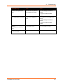
Appendix B: Binary to Hexadecimal Conversions
105
Converting Binary to Hexadecimal ___________________________________________ 105
Conversion Table _____________________________________________________ 105
Scientific Calculator _______________________________________________________ 105
Appendix C: Compliance
107
Device Label with CE Mark and FCC ID _______________________________________ 108
RoHS Notice ____________________________________________________________ 109
PremierWave XC User Guide
9
List of Figures
List of Figures
Figure 2-1 Product Label ____________________________________________________ 17
Figure 3-1 PremierWave XC Male DB9 DTE Serial Ports ___________________________ 19
Figure 3-2 PremierWave XC Pinout Configuration for RS-232 _______________________ 19
Figure 3-3 PremierWave XC Pinout Configuration for Full Duplex RS-422/485 (4-wire) ___ 19
Figure 3-4 PremierWave XC Pinout Configuration for Half Duplex RS-485 (2-wire) ______ 19
Figure 3-5 PremierWave XC Back Panel View ___________________________________ 20
Figure 3-6 PremierWave XC Top View _________________________________________ 21
Figure 3-7 PremierWave XC Side View ________________________________________ 22
Figure 3-8 PremierWave XC Bottom View ______________________________________ 23
Figure 3-9 PremierWave XC Connections ______________________________________ 24
Figure 3-10 PremierWave XC SIM Insertion _____________________________________ 24
Figure 3-11 PremierWave XC Dimensions ______________________________________ 25
Figure 5-1 Device Status Page _______________________________________________ 30
Figure 5-2 Components of the Web Manager Page _______________________________ 31
Figure 15-1 Filesystem Browser ______________________________________________ 98
Figure B-1 Hexadecimal Values in the Scientific Calculator ________________________ 106
List of Tables
Table 3-1 PremierWave XC LEDs and Descriptions _______________________________
Table 3-2 PremierWave XC Side View _________________________________________
Table 4-1 Device Detail Summary _____________________________________________
Table 5-1 Navigating Web Manager ___________________________________________
Table 6-1 WAN Connection Settings ___________________________________________
Table 6-2 DDNS Settings____________________________________________________
Table 6-3 Network Interface Settings __________________________________________
Table 6-4 Network 1 (eth0) Link Settings _______________________________________
Table 6-5 Network 2 (wwan0) SMS Outbound Settings ____________________________
Table 6-6 Network 2 (wwan0) SMS Inbound Settings ______________________________
Table 6-7 Network 2 (wwan0) Roam Settings ____________________________________
Table 6-8 Network 2 (wwan0) GSM/GPRS Bands Settings _________________________
Table 6-9 Network 2 (wwan0) SIM PIN Settings __________________________________
Table 6-10 Network 2 (wwan0) APN Configuration Settings _________________________
Table 6-11 Network 2 (wwan0) Carrier Connection Settings _________________________
Table 6-12 Network 2 (wwan0) SMS Statistics ___________________________________
Table 7-1 Line Configuration Settings __________________________________________
Table 7-2 Line Command Mode Settings _______________________________________
Table 7-3 Tunnel Serial Settings ______________________________________________
Table 7-4 Tunnel Packing Mode Settings _______________________________________
Table 7-5 Tunnel Accept Mode Settings ________________________________________
Table 7-6 Tunnel Connect Mode Settings _______________________________________
PremierWave XC User Guide
21
22
26
32
34
35
35
37
38
40
40
41
42
43
44
44
46
47
49
50
51
53
10
List of Tables
Table 7-7 Tunnel Disconnect Mode Settings _____________________________________ 55
Table 7-8 Tunnel Modem Emulation Settings ____________________________________ 56
Table 8-1 Terminal on Network and Line Settings _________________________________ 58
Table 8-2 Host Configuration _________________________________________________ 59
Table 9-1 DNS Settings _____________________________________________________ 61
Table 9-2 FTP Settings _____________________________________________________ 62
Table 9-3 Syslog Settings ___________________________________________________ 62
Table 9-4 HTTP Settings ____________________________________________________ 63
Table 9-5 HTTP Authentication Settings ________________________________________ 64
Table 9-6 RSS Settings _____________________________________________________ 66
Table 10-1 Certificate and Key Generation Settings _______________________________ 67
Table 10-2 Upload Certificate Settings _________________________________________ 69
Table 10-3 Trusted Authority Settings __________________________________________ 70
Table 11-1 File Display Settings ______________________________________________ 71
Table 11-2 File Modification Settings ___________________________________________ 72
Table 11-3 File Transfer Settings ______________________________________________ 72
Table 11-4 IP Network Stack Settings __________________________________________ 73
Table 11-5 ICMP Network Stack Settings _______________________________________ 74
Table 11-6 ARP Network Stack Settings ________________________________________ 74
Table 11-7 SMTP Network Stack Settings _______________________________________ 75
Table 11-8 SNMP Network Stack Settings ______________________________________ 75
Table 11-9 Query Port Settings _______________________________________________ 76
Table 11-10 Ping Settings ___________________________________________________ 77
Table 11-11 Traceroute Settings ______________________________________________ 78
Table 11-12 Log Settings ____________________________________________________ 79
Table 11-13 System Settings _________________________________________________ 81
Table 12-1 Email Configuration _______________________________________________ 82
Table 12-2 CLI Configuration Settings __________________________________________ 83
Table 12-3 Telnet Settings ___________________________________________________ 84
Table 12-4 SSH Settings ____________________________________________________ 85
Table 12-5 XML Exporting Configuration ________________________________________ 86
Table 12-6 Exporting Status _________________________________________________ 87
Table 12-7 Import Configuration from Filesystem Settings __________________________ 88
Table 12-8 Failover Settings _________________________________________________ 88
Table 12-9 Relay Output Settings _____________________________________________ 90
Table 13-1 Event Alerts Settings ______________________________________________ 91
Table 16-1 Short and Long Name Settings _____________________________________ 101
Table B-1 Binary to Hexadecimal Conversions __________________________________ 105
PremierWave XC User Guide
11
1:
Using This Guide
Purpose and Audience
This guide provides the information needed to configure, use, and update the PremierWave XC. It
is intended for software developers and system integrators who are deploying PremierWave in
their designs.
Summary of Chapters
The remaining chapters in this guide include:
Chapter
Description
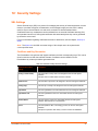
2: Introduction
Main features of the product and the protocols it supports.
Includes technical specifications.
3: Installing the PremierWave XC
Instructions for installing the PremierWave XC
4: Using DeviceInstaller
Instructions for viewing the current configuration using
DeviceInstaller.
5: Configuration Using Web Manager
Instructions for accessing Web Manager and using it to configure
settings for the device.
6: Network Settings
Instructions for configuring network settings.
7: Line and Tunnel Settings
Instructions for configuring line and tunnel settings.
8: Terminal and Host Settings
Instructions for configuring terminal and host settings.
9: Services Settings
Instructions for configuring DNS, DDNS, FTP, HTTP and Syslog
settings.
10: Security Settings
Instructions for configuring SSL security settings.
11: Maintenance and Diagnostics
Settings
Instructions to maintain the PremierWave XC, view statistics, files,
SNMP stack and diagnose problems.
12: Advanced Settings
Instructions for configuring email, failover, CLI and XML settings.
13: Events Configuration
Instructions for configuring events such as Input 1, Input 2, Main
Power Fail, Backup Power Fail, Cellular Link Down and Ethernet
Link Down to generate alerts.
14: Security in Detail
Detailed description and configuration of SSL security settings.
PremierWave XC User Guide
12
1: Using This Guide
Chapter
Description
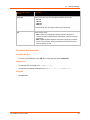
15: Updating Firmware
Instructions for obtaining the latest firmware and updating the
PremierWave XC.
16: Branding the PremierWave XC
Instructions on how to brand your device.
17: Troubleshooting
Describes common problems and error messages.
Appendix A: Technical Support
Instructions for contacting Lantronix Technical Support.
Appendix B: Binary to Hexadecimal
Conversions
Instructions for converting binary values to hexadecimals.
Appendix C: Compliance
Lantronix compliance information.
Additional Documentation
Visit the Lantronix Web site at www.lantronix.com/support/documentation for the latest
documentation and the following additional documentation.
Document
Description
PremierWave XC Command Reference
Instructions for accessing Command Mode (the command
line interface) using a Telnet connection, SSH connection or
through the serial port. Detailed information about the
commands. Also provides details for XML configuration and
status.
PremierWave XC Quick Start Guide
Instructions for getting the PremierWave XC up and
running.
DeviceInstaller Online Help
Instructions for using the Lantronix Windows-based utility to
locate the PremierWave XC and to view its current settings.
Com Port Redirector Quick Start and
Online Help
Instructions for using the Lantronix Windows-based utility to
create virtual com ports.
Secure Com Port Redirector User Guide
Instructions for using the Lantronix Windows-based utility to
create secure virtual com ports.
PremierWave XC User Guide
13
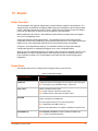
2:
Introduction
The PremierWave XC is a unique, hybrid Ethernet and GSM/GPRS dual port serial device server
which allows remote access to and management of virtually any IT/networking equipment or
device connected via Ethernet or GPRS through ‘Serial-tunneling’. Applications include medical
equipment, POS terminals or security equipment.
Key Features
Power Supply: Flexible power options and input voltage range (one barrel connector for
12V power supply, on terminal block connector for 09-30Vdc power supply)
Controller: 32-bit ARM9 microprocessor running at 400 megahertz (Mhz) with 32 KB Data
Cache and 32 Kilobytes (KB) internally based around the PremierWave EN
Memory: 64 MB SDRAM and 64 MB NAND Flash 8 MB serial SPI Flash
Ethernet: 10/100 Mbps Ethernet transceiver
Power: Redundant Hot Failover Power Supply via Power 1 and Power 2
Serial Ports: Two RS232/422/485 high-speed serial ports with all hardware handshaking
signals.Baud rate is software selectable (300 bps to 921600 bps). Both serial interfaces
support RS-485 termination resistors which can be software enabled.
USB Ports: Two USB 2.0 Full Speed (12 Mbps) Host ports, currently used for USB thumb
drive devices for storage
Failover (backup) Data Network Media Support for either Ethernet or GSM/GPRS
Events can be configured to generate alerts via SMS, SNMP trap and Relay Output
Temperature Range: Operates over an extended temperature range of -40°C to +70°C
Applications
The PremierWave XC device server connects serial devices such as those listed below to
Ethernet networks using the IP protocol family.
ATM machines
CNC controllers
Data collection devices
Universal Power Supply (UPS) management unit
Telecommunications equipment
Data display devices
Security alarms and access control devices
Handheld instruments
Time/attendance clocks and terminals
PremierWave XC User Guide
14
2: Introduction
Protocol Support
The PremierWave XC device server contains a full-featured IP stack. Supported protocols
include:
ARP, IP, UDP, TCP, ICMP, BOOTP, DHCP, Auto IP, Telnet, DNS, FTP, TFTP, SSH, SSL/TLS,
and Syslog for network communications and management
TCP, UDP tunneling to the serial port
TFTP for uploading/downloading files
FTP and HTTP for firmware upgrades and uploading/downloading files
Troubleshooting Capabilities
The PremierWave XC offers a comprehensive diagnostic toolset that lets you troubleshoot
problems quickly and easily. Available from the CLI or Web Manager, the diagnostic tools let you:
View critical hardware, memory, MIB-II, buffer pool, IP socket information and routing table
Perform ping and traceroute operations
Conduct forward or reverse DNS lookup operations
View all processes currently running on the PremierWave XC, including CPU utilization
View system log messages
Configuration Methods
After installation, the PremierWave XC requires configuration. For the unit to operate correctly on
a network, it must have a unique IP address on the network. There are four basic methods for
logging into the PremierWave XC and assigning IP addresses and other configurable settings:
Web Manager: View and configure all settings easily through a web browser using the Lantronix
Web Manager. (See Configuration Using Web Manager.)
DeviceInstaller: Configure the IP address and related settings and view current settings on the
PremierWave XC using a Graphical User Interface (GUI) on a PC attached to a network. (See
Using DeviceInstaller.)
Command Mode: There are two methods for accessing Command Mode (CLI): making a Telnet
or SSH connection, or connecting a terminal (or a PC running a terminal emulation program) to
the unit’s serial port. (See the PremierWave XC Command Reference Guide for instructions and
available commands.)
XML: The PremierWave XC supports XML-based configuration and setup records that make
device configuration transparent to users and administrators. XML is easily editable with a
standard text or XML editor. (See the PremierWave XC Command Reference Guide for
instructions and commands.)
PremierWave XC User Guide
15
2: Introduction
Addresses and Port Numbers
Hardware Address
The hardware address is also referred to as the Ethernet address or MAC address. The first three
bytes of the Ethernet address are fixed and identify the unit as a Lantronix product. The fourth,
fifth, and sixth bytes are unique numbers assigned to each unit.
Sample Hardware Address:
00-80-A3-14-01-18
00:80:A3:14:01:18
IP Address
Every device connected to an IP network must have a unique IP address. This address
references the specific unit.
Port Numbers
Every TCP connection and every UDP datagram is defined by a destination and source IP
address, and a destination and source port number. For example, a Telnet server commonly uses
TCP port number 23.
The following is a list of the default server port numbers running on the PremierWave XC:
TCP Port 22: SSH Server (Command Mode configuration)
TCP Port 23: Telnet Server (Command Mode configuration)
TCP Port 80: HTTP (Web Manager configuration)
UDP Port 161: SNMP
TCP Port 21: FTP
UDP Port 69: TFTP
UDP Port 30718: LDP (Lantronix Discovery Protocol) port
TCP/UDP Port 10001: Tunnel 1
TCP/UDP Port 10002: Tunnel 2
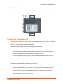
Product Information Label
The product information label on the unit contains the following information about the specific unit:
Part Number
International Mobile Equipment Identity (IMEI) Number
Hardware Address (MAC Address)
Country of Origin
Revision
Manufacturing Date Code
PremierWave XC User Guide
16
2: Introduction
Figure 2-1 Product Label
Part Number
International Mobile
Equipment Identity
Number
MAC Address
Country of Origin
PremierWave XC User Guide
Revision
Manufacturing
Date Code
17
3:
Installation of PremierWave XC
This chapter describes how to install the PremierWave XC device server. It contains the following
sections:
Package Contents
User-Supplied Items
Hardware Components
Installing the PremierWave XC
Package Contents
The PremierWave XC package includes the following items:
PremierWave XC device
3-pin Terminal Mating Connector
6-pin Terminal Mating Connector
RJ-45 Ethernet Straight Cat5 Cable, 1.5 meter
External Antenna, SMA Connector
Power Supply 12VDC with International Adapters
Mounting Components (DIN Rail Mounting Adapter, Cover Plates, and Rubber Feet)
Quick Start Guide
User-Supplied Items
To complete your installation, you need the following items:
RS-232/422/485 serial devices that require network connectivity.
-
A serial cable, as listed below, for each serial device. One end of the cable must have a
female DB9 connector for the serial port.
-
A null modem cable to connect the serial port to another DTE device.
-
A straight-through modem cable to connect the serial port to a DCE device.
An available connection to your Ethernet network and an Ethernet cable.
A working SIM card from your Network Carrier or Service Provider
A working DDNS Account with DynDNS.com
A working power outlet if the unit will be powered from an AC outlet using the included
12VDC power supply.
An additional power supply (9-30VDC) to power the device using the 3-pin terminal
connector.
PremierWave XC User Guide
18
3: Installation of PremierWave XC
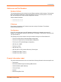
Hardware Components
The PremierWave XC has two male DB9 serial ports that support RS-232/422/485. Figure 3-1
shows the front panel view of the device. The default serial port settings are 9600 baud, 8 bits, no
parity, 1 stop bit, no flow control.
Figure 3-1 PremierWave XC Male DB9 DTE Serial Ports
Figure 3-2 PremierWave XC Pinout Configuration for RS-232
Figure 3-3 PremierWave XC Pinout Configuration for Full Duplex RS-422/485 (4-wire)
Figure 3-4 PremierWave XC Pinout Configuration for Half Duplex RS-485 (2-wire)
PremierWave XC User Guide
19
3: Installation of PremierWave XC
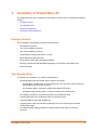
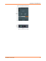
Back Panel
On the PremierWave XC back panel, there is a Barrel Connector for Primary Power (Power 1), 3Pin Terminal Connector for Secondary Power (Power 2), USB 1, USB 2, RJ-45 Ethernet Port and
Reset button as shown in Figure 3-5.
Figure 3-5 PremierWave XC Back Panel View
The Ethernet Port has two LEDs that indicate the status of the connection as follows:
Left LED
-
Green ON 100 Mbps Link
-
Green Blink 100 Mbps Activity
-
Amber ON 10 Mbps Link
-
Amber Blink 10 Mbps Activity
Right LED
-
Green ON Full Duplex
-
OFF Half Duplex
The Ethernet port can connect to an Ethernet (10 Mbps) or Fast Ethernet (100 Mbps) network.
Reset Button
You can reset the PremierWave XC to factory defaults, including clearing the network settings.
The IP address, gateway, and netmask are set to 00s. To reset the unit to factory defaults,
perform the following steps.
1.
Place the end of a paper clip or similar object into the Reset button opening and hold down for a
minimum of 10-15 seconds.
2.
Remove the paper clip to release the button. The unit will continue the boot process restoring it back to
the original factory default settings.
PremierWave XC User Guide
20
3: Installation of PremierWave XC
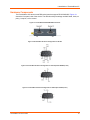
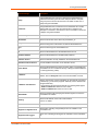
Top Panel
Figure 3-6 shows the top panel view of the PremierWave XC. Table 3-1 list and describes the
LEDs.
Figure 3-6 PremierWave XC Top View
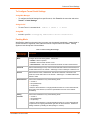
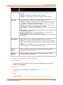
Table 3-1 PremierWave XC LEDs and Descriptions
LED
Description
Power
GREEN – power is properly supplied
OFF – no power supplied
GSM/GPRS
GREEN - GPRS is connected (e.g. after an APN has been properly
configured)
AMBER - GSM is connected. Once the radio connection has been established
with the cellular provider.
OFF – no connection. Reasons for OFF are that it cannot register with the
cellular provider (wrong PIN code, cellular provider unavailable, or incorrect
APN).
Serial 1
GREEN – Serial port 1 is transmitting data
AMBER – Serial port 1 is receiving data
OFF – no data is being transmitted or received through Serial port 1
Serial 2
GREEN – Serial port 2 is transmitting data
AMBER – Serial port 2 is receiving data
OFF – no data is being transmitted or received through Serial port 2
PremierWave XC User Guide
21
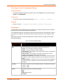
3: Installation of PremierWave XC
LED
Description
USB 1
GREEN - a USB device is connected to USB 1 Host port and is functioning
properly
OFF- no USB device is connected to USB 1 Host port
USB 2
GREEN - a USB device is connected to USB 2 Host port and is functioning
properly
OFF- no USB device is connected to USB 2 Host port
Fault
RED- blinking when Events or Errors occurred
OFF - system functioning normally
GSM Signal Strength
GREEN – 3 to 5 LEDs lighted. Good to Strong signal strength
AMBER/GREEN – 1 to 2 bi-colored LEDs lighted. Weak signal strength
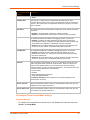
Side Panel
On the PremierWave XC side panel, there is a 6-pin Terminal Connector for Relay and I/Os as
well as an SMA Antenna Connector as shown in Figure 3-7.
Figure 3-7 PremierWave XC Side View
Table 3-2 PremierWave XC Side View
Connector
Description
Relay Output
Outputs Support 1A 24V
Inputs accept voltage 0 to 30 VDC
Max
30 VDC
Min
2 VDC
Max
0.7 VDC
Min
0 VDC
ON
Inputs
OFF
Antenna
PremierWave XC User Guide
Connect the provided SMA Antenna
22
3: Installation of PremierWave XC
Bottom Panel
On the PremierWave XC bottom panel, there is a SIM cover as shown in Figure 3-8.
Figure 3-8 PremierWave XC Bottom View
Installing the PremierWave XC
Be sure to place or mount the device securely on a flat horizontal or vertical surface. The device
comes with mounting brackets for mounting the device vertically, for example on a wall. If using
AC power, avoid outlets controlled by a wall switch.
Observe the following guidelines when connecting the serial devices:
PremierWave XC serial ports support RS-232/422/485
A null modem cable is the best cable to connect the serial port to another DTE device. The
straight-though (modem) cable is the best cable to connect the serial port to a DCE device.
Connect your RJ-45 Ethernet cable to the RJ-45 serial port of the unit
The device supports a power range of 9 to 30 VDC. You can power up the device with the
included 12VDC power supply with barrel-power connector and/or the 3-pin terminal connector
for backup power supply.
Note: As soon as you plug the device into power, the device powers up automatically,
the self-test begins, and LEDs indicate the device's status.
Perform the following steps to install your device (see Figure 3-9):
1.
Remove the SIM compartment door, secured by two screws. Open the SIM slot fastener (sliding top
fastener towards Power connector) and Insert the SIM card into the SIM slot (with contacts facing
toward main board). Close and lock the SIM slot fastener (sliding top fastener away from Power
connector). Secure the SIM compartment door accordingly and secure with screws provided.
2.
Connect the Antenna to the SMA connector on the side. Do note that the Safe Distance due to RF
exposure from Antenna is 23cm (see Figure 3-9).
PremierWave XC User Guide
23
3: Installation of PremierWave XC
3.
Connect serial devices to the serial port of the unit.
4.
Connect an RJ-45 Ethernet cable between the unit and your Ethernet network.
5.
Plug the PremierWave XC into the power outlet by using the power supply that was included in the
packaging.
6.
Power up Serial Devices.
Figure 3-9 PremierWave XC Connections
Figure 3-10 PremierWave XC SIM Insertion
PremierWave XC User Guide
24
3: Installation of PremierWave XC
Figure 3-11 PremierWave XC Dimensions
PremierWave XC User Guide
25
4:
Using DeviceInstaller
This chapter covers the steps for locating a PremierWave XC unit and viewing its properties and
device details. DeviceInstaller is a free utility program provided by Lantronix that discovers,
configures, upgrades and manages Lantronix Device Servers.
Notes:
For instructions on using DeviceInstaller to configure the IP address and related settings
or for more advanced features, see the DeviceInstaller Online Help.
Auto IP generates a random IP address in the range of 169.254.0.1 to 169.254.255.254,
with a netmask of 255.255.0.0, if no BOOTP or DHCP server is found.
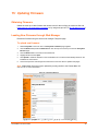
Accessing PremierWave XC using DeviceInstaller
Notes: Make note of your PremierWave XC MAC address. It is needed to locate the
PremierWave XC using DeviceInstaller.
To use the DeviceInstaller utility, first install the latest version from the downloads page on the
Lantronix web site http://www.lantronix.com/downloads.
1.
Run the executable to start the installation process and respond to the installation wizard prompts. (If
prompted to select an installation type, select Typical.)
2.
Click Start -> All Programs -> Lantronix -> DeviceInstaller -> DeviceInstaller.
3.
When DeviceInstaller starts, it will perform a network device search. To perform another search, click
Search.
4.
Expand the PremierWave folder by clicking the + symbol next to the PremierWave folder icon. A list of
available Lantronix PremierWave devices appears.
5.
Select the PremierWave XC unit by expanding its entry and clicking on its MAC address to view its
configuration.
6.
On the right page, click the Device Details tab. The current PremierWave XC configuration appears.
This is only a subset of the full configuration; the full configuration may be accessed via Web Manager,
CLI or XML.
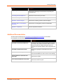
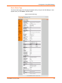
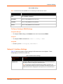
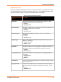
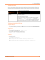
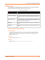
Device Detail Summary
Notes: The settings are Display Only in this table unless otherwise noted.
Table 4-1 Device Detail Summary
Current Settings
Description
Name
Name identifying the PremierWave XC.
DHCP Device Name
The name associated with the PremierWave XC module’s current IP
address, if the IP address was obtained dynamically.
PremierWave XC User Guide
26
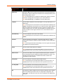
4: Using DeviceInstaller
Current Settings
Description
Group
Configurable field. Enter a group to categorize the PremierWave XC.
Double-click the field, type in the value, and press Enter to complete.
This group name is local to this PC and is not visible on other PCs or
laptops using DeviceInstaller.
Comments
Configurable field. Enter comments for the PremierWave XC. Doubleclick the field, type in the value, and press Enter to complete. This
description or comment is local to this PC and is not visible on other PCs
or laptops using DeviceInstaller.
Device Family
Shows the PremierWave XC device family type as “PremierWave”.
Short Name
Shows the short name of the device as premierwave_xc.
Long Name
Shows the long name of the device as Lantronix PremierWave XC.
Type
Shows the device type as “PremierWave XC”.
ID
Shows the PremierWave XC ID embedded within the unit.
Hardware Address
Shows the PremierWave XC hardware (MAC) address.
Firmware Version
Shows the firmware currently installed on the PremierWave XC.
Extended Firmware Version
Provides additional information on the firmware version.
Online Status
Shows the PremierWave XC status as Online, Offline, Unreachable (the
PremierWave XC is on a different subnet), or Busy (the PremierWave XC
is currently performing a task).
IP Address
Shows the PremierWave XC current IP address. To change the IP
address, click the Assign IP button on the DeviceInstaller menu bar.
IP Address was Obtained
Appears “Dynamically” if the PremierWave XC automatically received an
IP address (e.g., from DHCP). Appears “Statically” if the IP address was
configured manually.
If the IP address was assigned dynamically, the following fields appear:
Obtain via DHCP with values of True or False.
Obtain via BOOTP with values of True or False.
Subnet Mask
Shows the subnet mask specifying the network segment on which the
PremierWave XC resides.
Gateway
Shows the IP address of the router of this network.
There is no default.
Number of Ports
Shows the number of serial ports on this PremierWave XC.
Supports Configurable Pins
Shows False, indicating configurable pins are not available on the
PremierWave XC.
Supports Email Triggers
Shows True, indicating email triggers are available on the PremierWave
XC.
PremierWave XC User Guide
27
4: Using DeviceInstaller
Current Settings
Description
Telnet Supported
Shows True, indicating telnet is supported on this PremierWave XC.
Telnet Port
Shows the PremierWave XC port for Telnet sessions.
Web Port
Shows the PremierWave XC port for Web Manager configuration.
Firmware Upgradable
Shows True, indicating the PremierWave XC firmware is upgradable as
newer versions become available.
PremierWave XC User Guide
28
5:
Configuration Using Web Manager
This chapter describes how to configure the PremierWave XC using Web Manager, the Lantronix
browser-based configuration tool. The unit’s configuration is stored in nonvolatile memory and is
retained without power. All changes take effect immediately, unless otherwise noted. It contains
the following sections:
Accessing Web Manager
Web Manager Page Components
Navigating the Web Manager
Accessing Web Manager
You can also access the Web Manager by selecting the Web Configuration tab on the
DeviceInstaller window.
To access Web Manager, perform the following steps:
Open a standard web browser. Lantronix supports the latest version of Internet Explorer,
Mozilla Suite, Mozilla Firefox, Safari, Chrome or Opera.
Enter the IP address of the PremierWave XC in the address bar. The IP address may have
been assigned manually using DeviceInstaller or automatically by DHCP.
Enter your username and password.The factory-default username is “admin” and the factorydefault password is “PASS.” The Device Status web page displays configuration, network
settings, line settings, tunneling settings, and product information.
Note: The Logout button is available on any web page. Logging out of the web page
would force re-authentication to take place the next time the web page is accessed.
PremierWave XC User Guide
29
5: Configuration Using Web Manager
Device Status Page
The Device Status page is the first page that appears after you log into the Web Manager. It also
appears when you click Status in the Main Menu.
Figure 5-1 Device Status Page
PremierWave XC User Guide
30
5: Configuration Using Web Manager
Web Manager Page Components
The layout of a typical Web Manager page is below.
Figure 5-2 Components of the Web Manager Page
Items to
Configure
Links to
Subpages
Logout
Button
Header
Menu Bar
Footer
Configuration and/or Status Area
Information
and Help Area
The menu bar always appears at the left side of the page, regardless of the page shown. The
menu bar lists the names of the pages available in the Web Manager. To bring up a page, click it
in the menu bar.
The main area of the page has these additional sections:
At the very top, many pages, such as the one in the example above, enable you to link to sub
pages. On some pages, you must also select the item you are configuring, such as a line or a
tunnel.
In the middle of many pages, you can select or enter new configuration settings. Some pages
show status or statistics in this area rather than allow you to enter settings.
At the bottom of most pages, the current configuration is displayed. In some cases, you can
reset or clear a setting.
The information or help area shows information or instructions associated with the page.
PremierWave XC User Guide
31
5: Configuration Using Web Manager
A Logout link is available at the upper right corner of every web page. In Chrome or Safari, it
is necessary to close out of the browser to completely logout. If necessary, reopen the
browser to log back in.
The footer appears at the very bottom of the page. It contains copyright information and a link
to the Lantronix home page.
Navigating the Web Manager
The Web Manager provides an intuitive point-and-click interface. A menu bar on the left side of
each page provides links you can click to navigate from one page to another. Some pages are
read-only, while others let you change configuration settings.
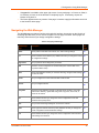
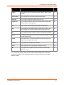
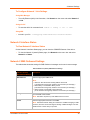
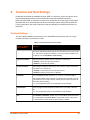
Table 5-1 Navigating Web Manager
Web Manager
Page
Description
See
Page
Status
Shows product information and network, line, and tunneling settings.
30
CLI
Shows Command Line Interface (CLI) statistics and lets you change the current 83
CLI configuration settings.
Diagnostics
Lets you perform various diagnostic procedures.
77
DNS
Shows the current configuration of the DNS subsystem and the DNS cache,
and perform DNS Lookup.
61
Email
Shows email statistics and lets you clear the email log, configure email settings, 82
and send an email.
Events
Lets you configure the events and alerts that would be used.
91
Failover
Lets you configure Failover.
88
Filesystem
Shows file system statistics and lets you browse the file system to view a file,
create a file or directory, upload files using HTTP, copy a file, move a file, or
perform TFTP actions.
71
FTP
Shows statistics and lets you change the current configuration for the File
Transfer Protocol (FTP) server.
62
Host
Lets you view and change settings for a host on the network.
59
HTTP
Shows HyperText Transfer Protocol (HTTP) statistics and lets you change the
current configuration and authentication settings.
63
Line
Shows statistics and lets you change the current configuration and Command
mode settings of a serial line.
46
PremierWave XC User Guide
32
5: Configuration Using Web Manager
Web Manager
Page
Description
See
Page
Network
Shows status and lets you configure the network interface, WAN connection,
and DDNS.
34
Protocol Stack
Lets you perform lower level network stack-specific activities.
73
Query Port
Lets you change configuration settings for the query port.
76
Relay Output
Lets you change the Initiation State, and customise the Relay output SMS
command to open, close Relay Output.
90
RSS
Lets you change current Really Simple Syndication (RSS) settings.
66
SSH
Lets you change the configuration settings for SSH server host keys, SSH
server authorized users, SSH client known hosts, and SSH client users.
85
SSL
Lets you upload an existing certificate or create a new self-signed certificate.
67
Syslog
Lets you specify the severity of events to log and the server and ports to which
the syslog should be sent.
62
System
Lets you reboot device, restore factory defaults, upload new firmware, and
change the device long and short names.
81
Terminal
Lets you change current settings for a terminal.
58
Tunnel
Lets you change the current configuration settings for a tunnel.
49
XML
Lets you export XML configuration and status records, and import XML
85
configuration records.
Note: There may be times when you must reboot the PremierWave XC for the new
configuration settings to take effect. The chapters that follow indicate when a change
requires a reboot.
PremierWave XC User Guide
33
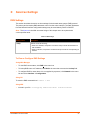
6:
Network Settings
The PremierWave XC contains two network interfaces. The Ethernet interface is also called
Network 1 or eth0, and the Cellular interface is called Network 2 or wwan0.
The Network Settings show the status of the Ethernet or Cellular interface/link and let you
configure the settings on the device. Interface settings are related to the configuration of the IP
and related protocols. Link settings are related to the physical link connection, which carries the
respective network traffic.
Notes:
Some settings require a reboot to take effect. These settings are noted below.
The blue text in the XML command strings of this chapter are to be replaced with a userspecified name.
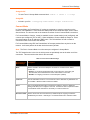
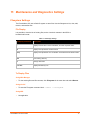
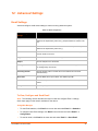
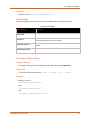
WAN Connection Settings
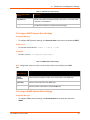
Table 6-1 shows the settings for the Wide Area Network (WAN) that can be configured.
Table 6-1 WAN Connection Settings
WAN Connection Settings
Description
Network
Select Wwan0 or Eth0 to be your default connection.
To Configure WAN Connection Settings
Using Web Manager
To configure WAN Connection settings, click Network in the menu bar and select WAN
Connection.
Using the CLI
To enter the WAN Connection command level:
connection
enable -> config → wan
Using XML
Include in your file: <configgroup name=”wan connection”>
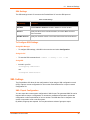
DDNS Settings
This section describes the configuration settings for DynDNS (DDNS). You would need an
account with DynDns.com. This would allow the device to connect to a sub-domain with regularly
changing IP address.
PremierWave XC User Guide
34
6: Network Settings
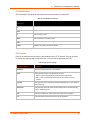
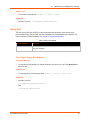
Table 6-2 DDNS Settings
Note: A valid account with DynDNS.com is necessary for this service to work.
Setting / Field
Description
State
Select Enabled or Disabled.
User Name
Enter or modify DDNS account user name.
Password
Enter or modify DDNS account password.
Domain
Enter or modify DDNS account host domain.
To View or Configure DDNS Settings
Using Web Manager
To configure DDNS settings, click Network in the menu bar and select DDNS.
Using CLI
To configure DDNS command level: enable -> config -> ddns
Using XML
Include in your file: <configgroup name=”ddns”>
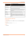
Network 1 Interface Settings
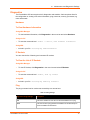
Table 6-3 shows the network interface settings for Ethernet that can be configured. These
settings apply to the Ethernet (eth0) only.
Table 6-3 Network Interface Settings
Network Interface
Settings
Description
BOOTP Client
Select On or Off. At boot up, after the physical link is up, the PremierWave XC
will attempt to obtain IP settings from a BOOTP server.
Note: Overrides the configured IP address/mask, gateway, hostname, and
domain. When DHCP is On, the system automatically uses DHCP, regardless of
whether BOOTP is On. Changing this value requires you to reboot the device.
PremierWave XC User Guide
35
6: Network Settings
Network Interface
Settings
Description
DHCP Client
Select On or Off. At boot up, after the physical link is up, the PremierWave XC
will attempt to obtain IP settings from a DHCP server and will periodically renew
these settings with the server.
Note: Overrides BOOTP, the configured IP address/mask, gateway, hostname,
and domain. Changing this value requires you to reboot the device.
Note: Within WebManager, click Renew to renew the DHCP lease.
IP Address
Enter the static IP address to use for the interface. You may enter it alone or in
CIDR format.
Note: This setting will be used if Static IP is active (both DHCP and BOOTP are
Disable). Changing this value requires you to reboot the device. When DHCP or
BOOTP is enabled, the PremierWave XC tries to obtain an IP address from a
DHCP or BOOTP server. If it cannot, the PremierWave XC generates and uses
an Auto IP address in the range of 169.254.xxx.xxx, with a network mask of
255.255.0.0.
Default Gateway
Enter the IP address of the router for this network.
Note: This setting will be used if Static IP is active (both DHCP and BOOTP are
Disable).
Hostname
Enter the hostname for the interface. It must begin with a letter or number,
continue with a sequence of letters, numbers, or hyphens, and end with a letter
or number.
Note: This setting will take effect immediately, but will not register the hostname
with a DNS server until the next reboot.
Domain
Enter the domain name suffix for the interface.
Note: This setting will be used when either Static IP or Auto IP is active, or if
DHCP/BOOTP is active and no Domain Suffix was acquired from the server.
DHCP Client ID
Enter the ID if the DHCP server requires a DHCP Client ID option. The DHCP
server’s lease table shows IP addresses and MAC addresses for devices. The
lease table shows the Client ID, in hexadecimal notation, instead of the
PremierWave XC MAC address.
Primary DNS
Enter the IP address of the primary Domain Name Server.
Note: This setting will be used when either Static IP or Auto IP is active, or if
DHCP/BOOTP is active and no DNS server was acquired from the server.
Secondary DNS
Enter the IP address of the secondary Domain Name Server.
Note: This setting will be used when either Static IP or Auto IP is active, or if
DHCP/BOOTP is active and no DNS server was acquired from the server.
MTU
PremierWave XC User Guide
When DHCP is enabled, the MTU size is (usually) provided with the IP address.
When not provided by the DHCP server, or using a static configuration, this
value is used. The MTU size can be from 576 to 1500 bytes, the default being
1500 bytes.
36
6: Network Settings
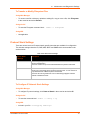
To Configure Network 1 Interface Settings
Using Web Manager
To modify Ethernet (eth0) settings, click Network on the menu and select Network 1 ->
Interface -> Configuration.
Using the CLI
To enter the eth0 command level: enable -> config -> if 1
Using XML
Include in your file: <configgroup name="interface" instance="eth0">
To View Network 1 Interface Status
Using Web Manager
On the Network Interface Status page, you can view both the current operational settings as well
as the settings that would take effect upon a device reboot.
To view the Ethernet (eth0) Status page, click Network on the menu and select Network 1 ->
Interface -> Status.
Network 1 Link Settings
Physical link parameters can be configured for an Ethernet (eth0) Network Interface (see table
below).
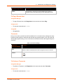
Table 6-4 Network 1 (eth0) Link Settings
Network 1 Ethernet (eth0)
Link Settings
Description
Speed
Select the Ethernet link speed. (Default is Auto)
Auto = Auto-negotiation of Link Speed
10 Mbps = Force 10 Mbps
100 Mbps = Force 100 Mbps
Duplex
Select t he Ethernet link duplex mode. (Default is Auto)
Auto = Auto-negotiation of Link Duplex
Half = Force Half Duplex
Full = Force Full Duplex
Notes:
When speed is Auto, duplex must be Auto or Half.
When speed is not Auto, duplex must be Half or Full.
Fixed speed Full duplex will produce errors connected to Auto, due to duplex mismatch.
PremierWave XC User Guide
37
6: Network Settings
To Configure Network 1 Link Settings
Using Web Manager
To modify Ethernet (eth0) Link information, click Network on the menu and select Network 1
-> Link.
Using the CLI
To enter the eth0 Link command level: enable -> config -> if 1 -> link
Using XML
Include in your file: <configgroup name="ethernet" instance="eth0">
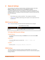
Network 2 Interface Status
To View Network 2 Interface Status
On the Network 2 Interface Status page, you can view the GSM/GPRS status of the device.
To view the Network 2 (wwan0) Status page, click Network on the menu bar and select
Network 2 -> Status.
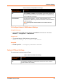
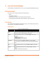
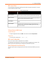
Network 2 SMS Outbound Settings
The table below shows the settings for SMS Outbound messages and to send a test message.
Table 6-5 Network 2 (wwan0) SMS Outbound Settings
Network 2 (wwan0)
SMS Outbound Settings
Description
SMS Outbound
Select the appropriate SMS format.
Note:
Select the Text ASCII when sending SMS in Text format
(7 bit characters and typically limited to 160 characters per message.)
Select Binary to send SMS in Binary format.
(8 bit characters and typically limited to 140 characters per message.)
Select Unicode to send SMS in Unicode format.
(16 bit characters and typically limited to 70 characters per message.)
Message Center No.
Input the SMS center Number.
Note: This field is required only if the SMS center is incorrect.
Channel
Select the appropriate Channel to send SMS.
Note: The default network setting for transmission of SMS messaging is GSM.
However, there are carriers that support sending of SMS messages over their
GPRS network. Check with your provider.
PremierWave XC User Guide
38
6: Network Settings
Network 2 (wwan0)
SMS Outbound Settings
Description
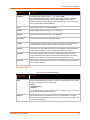
Test Phone Number
Input the test recipient's phone number.
Test Message Body
Input the Test Message Body.
Note: SMS Format is to be accordingly to the Message Body.
When Text ASCII is selected
(7 bit characters and typically limited to 160 characters per message.)
When Binary is selected
(8 bit characters and typically limited to 140 characters per message.)
When Unicode is selected
(16 bit characters and typically limited to 70 characters per message.)
Send Test Message
(button)
Click to send out Test SMS Message
Note: This will test the SMS Outbound configured settings with the test phone
number and test message body.
To Configure Network 2 SMS Outbound Settings
Using Web Manager
To modify Network 2 SMS Outbound settings, click Network on the menu bar and select
Network 2 → Configuration → SMS Outbound
Using the CLI
To enter the Network 2 SMS outbound command level:
enable -> config -> if 2 ->link -> sms outbound
Using XML
Include in your file:
<configgroup name="sms outbound">
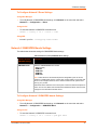
Network 2 SMS Inbound Settings
This device will accept inbound SMS messages and perform specific actions based on the
message content. Currently this device allows SMS messages to control the relay states: Open or
Close. The SMS Inbound message content is checked against configured strings associated with
relay output actions: Open or Close. When there is a match, the relay action is performed.
For added security, the SMS Inbound feature supports configuration of a whitelist, of up to 5
phone numbers from where it will accept messages.
All SMS Inbound messages will be discarded if the SMS Inbound State is Disabled or the phone
number is not configured in the Received Number list.
The table below shows the settings for SMS Inbound, and Received Number whitelist.
PremierWave XC User Guide
39
6: Network Settings
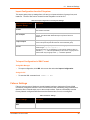
Table 6-6 Network 2 (wwan0) SMS Inbound Settings
Network 2 (wwan0)
SMS Inbound Settings
Description
State
Select Enabled or Disabled. When Enabled and the number matches an
entry in the whitelist, the device will handle the SMS. When Disabled, any
received SMS will be discarded.
Received Number
Input the Received Number . At least 1 Received Number must be
configured for an SMS to be processed. A maximum of 5 Received Number
entries are allowed.
Note: Please input the Received Numbers to be included in device's
whitelist.
To Configure Network 2 SMS Inbound Settings
Using Web Manager
To modify Network 2 SMS Inbound settings, click Network on the menu bar and select
Network 2 → Configuration → SMS Inbound
Using the CLI
To enter the Network 2 SMS outbound command level:
enable -> config -> if 2 ->link -> sms inbound
Using XML
Include in your file:
<configgroup name="sms inbound">
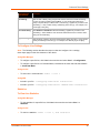
Network 2 Roam Settings
The table below shows the settings for Roam.
Table 6-7 Network 2 (wwan0) Roam Settings
Network 2 (wwan0)
Roam Settings
Description
State
Select Enabled or Disabled. Enabled allows the device to roam. Disabled
prevents the device from roaming.
PremierWave XC User Guide
40
6: Network Settings
To Configure Network 2 Roam Settings
Using Web Manager
To modify Network 2 GSM/GPRS band settings, click Network on the menu bar and select
Network 2 → Configuration → Roam
Using the CLI
To enter the Network 2 GSM/GPRS command level:
enable -> config -> if 2 ->link -> roam
Using XML
Include in your file: <configgroup name="roam">
Network 2 GSM/GPRS Bands Settings
The table below shows the settings for GSM/GPRS Bands settings.
Table 6-8 Network 2 (wwan0) GSM/GPRS Bands Settings
Network 2 (wwan0)
GSM/GPRS Settings
Description
GSM/GPRS Bands
Select the GSM/GPRS Bands if needed:
Auto (Default)
GSM-900
GSM-1800
GSM-850
GSM-1900
Note: These bands are the wwan0 frequencies designated by the ITU for the
operation of GSM mobile phones. Typically Auto should suffice in most cases and
should not be changed unless the unit is unable to determine the specific band
used by your provider.
GSM bands 900 & 1800 are used in most parts of the world, with the exception of
places such as USA, Brazil and Canada where GSM bands 850 & 1900 are used.
Changes do not take effect until after reboot.
To Configure Network 2 GSM/GPRS bands Settings
Using Web Manager
To modify Network 2 GSM/GPRS band settings, click Network on the menu bar and select
Network 2 → Configuration → GSM/GPRS Band
Using the CLI
To enter the Network 2 GSM/GPRS command level:
enable -> config -> if 2 ->link -> gsm gprs band
PremierWave XC User Guide
41
6: Network Settings
Using XML
Include in your file: <configgroup name="gsm gprs band">
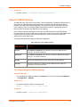
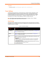
Network 2 SIM Pin Settings
The SIM PIN is a 4 digit numeric code used to unlock the SIM card. This allows mobile devices to
gain access to network specific information stored on the SIM. If the SIM PIN functionality is
enabled on the SIM card, Network Registration will not start until after a valid PIN number has
been configured. This is for both the GSM and and GPRS networks. Typically SIM cards are
delivered from the provider with SIM PIN function disabled.
Upon 3 failed consecutive attempts to enter a pin, your SIM card will be locked (old PIN will
become invalid). To unlock the SIM card, you will have to contact the provider of the SIM card and
request a PIN Unlock (PUK) code. Use this with extreme caution, because 10 failed PUK
attempts will lock the SIM forever!
The table below shows the settings for SIM PIN configuration.
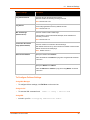
Table 6-9 Network 2 (wwan0) SIM PIN Settings
Network 2 (wwan0)
SIM Pin Settings
Description
PIN Lock
Select Enabled or Disabled to elect whether to protect your SIM card with a
security pin. The default is Disabled.
Auto Unlock
Select Enabled or Disabled to elect whether to unlock the SIM card with a preset
security pin. The default is Disabled.
PIN Code
Enter the personal identification number / password to access SIM card.
PUK Code
Enter the Pin Unlock Key to unblock a blocked SIM card that is locked by 3
consecutive incorrect pin code entries.
To Configure Network 2 SIM Pin Settings
Using Web Manager
To modify Network 2 SIM Pin settings, click Network on the menu bar and select Network 2
→ Configuration → SIM PIN
Using the CLI
To enter the Network 2 SIM Pin command level:
enable -> config -> if 2 -> link -> pin
Using XML
Include in your file: <configgroup name="pin">
PremierWave XC User Guide
42
6: Network Settings
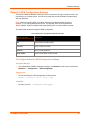
Network 2 APN Configuration Settings
The APN is a Network Identifier used by the carrier to determine the type of network service you
requested for your mobile device. Your service provider will provide the APN information along
with your SIM card.
Note: Make sure that the APN, User Name, Password and Dialup Number is entered
correctly. If not, GPRS attachment would fail. This typically refers to the Data Network
Access (GPRS). GSM (Text SMS) functionality typically does not require APN to operate.
The table below shows the settings for APN configuration.
Table 6-10 Network 2 (wwan0) APN Configuration Settings
Network 2 (wwan0)
Description
APN Configuration Settings
APN
Enter Access Point Name (APN).
User name
Enter or modify user name.
Password
Enter or modify password.
Dialup number
Enter or modify dialup number of APN.
To Configure Network 2 APN Configuration Settings
Using Web Manager
To modify Network 2 APN Configuration settings, click Network on the menu bar and select
Network 2 → Configuration → APN Configuration
Using the CLI
To enter the Network 2 APN Configuration command level:
enable -> config -> if 2 -> link -> apn
Using XML
Include in your file: <configgroup name="ppp">
PremierWave XC User Guide
43
6: Network Settings
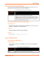
Network 2 Carrier Connection Settings
The Carrier Connection is the identity of the carrier(s) supported by the SIM card provider. The
table below shows the settings for Carrier Connection configuration.
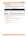
Table 6-11 Network 2 (wwan0) Carrier Connection Settings
Network 2 (wwan0)
Carrier Connection
Settings
Description
Carrier Connection This identifies the carriers supported by the SIM card provider.
Auto allows the device to determine which carrier best matches the SIM card
configuration. Select Auto, unless your service provider directs you to change it.
If Manual is selected, you will have to run the Network Scan function to see a list
of the carriers supported based on the SIM card. Refer to the your SIM card
service provider as to which carrier to select.
To Configure Network 2 Carrier Connection Settings
Using Web Manager
To modify Network 2 Carrier Connection settings, click Network on the menu bar and select
Network 2 → Configuration → Carrier Connection
Using the CLI
To enter the Network 2 Carrier Connection command level:
enable -> config -> if 2 -> link -> carrier
Using XML
Include in your file: <configgroup name="carrier">
Network 2 SMS Statistics
To View Network 2 SMS Statistics
Using Web Manager
To view Network 2 SMS Statistics, click Network on the menu bar and select Network 2 →
SMS Statistics
Table 6-12 Network 2 (wwan0) SMS Statistics
Network 2 (wwan0)
SMS Statistics
Sender
PremierWave XC User Guide
Description
Displays the current sender information for the wwan0 module.
44
6: Network Settings
Network 2 (wwan0)
SMS Statistics
Description
Timestamp
Displays the timestamp information for the wwan0 module.
Content
Displays the current content of the wwan0 module.
PremierWave XC User Guide
45
7:
Line and Tunnel Settings
The PremierWave XC contains two Lines. Lines 1 and 2 are standard RS232/RS485 serial ports.
RS232/RS422/RS485
Lines 1 and 2 can be configured to operate in the following modes:
RS232
RS422/RS485 Full Duplex
RS422/RS485 Half Duplex, with and without termination impedance
All serial settings such as Baud Rate, Parity, Data Bits, etc, apply to these Lines.
Line Settings
The Line Settings allow configuration of the serial Lines (ports). Some settings may be specific to
only certain Lines. Such settings are noted below.
Configuration
Table 7-1 Line Configuration Settings
Line Settings
Description
Name
Enter a name or short description for the line, if desired. By default, there is no name
specified. A name that contains white space must be quoted.
Interface
Sets the interface type for the Line. The default is RS232 for Lines 1 and 2.
Choices are:
RS232 (Lines 1 and 2 only)
RS485 Full-Duplex (Lines 1 and 2 only)
RS485 Half-Duplex (Lines 1 and 2 only)
Termination
Sets the Line Termination to Enabled or Disabled. The default is Disable.
Note: This setting is only relevant for Lines 1 and 2 with Interface type RS485 HalfDuplex.
State
Sets the operational state of the Line to either Enable or Disable. The default is
Enable.
Protocol
Sets the operational protocol for the Line. The default is Tunnel. Choices are:
None
Tunnel = Serial-Network tunneling protocol.
PremierWave XC User Guide
46
7: Line and Tunnel Settings
Line Settings
Description
Baud Rate
Sets the Baud Rate (speed) of the Line. The default is 9600.
Any set speed between 300 and 921600 may be selected: 300, 600, 1200, 2400,
4800, 9600, 19200, 38400, 57600, 115200, 230400, 460800, 921600. When
selecting Custom baud rate (available for line 1 and line 2 only), you may manually
enter any value between 300 and 5000000.
Parity
Sets the Parity of the Line. The default is None.
Data Bits
Sets the number of data bits for the Line. The default is 8.
Stop Bits
Sets the number of stop bits for the Line. The default is 1.
Flow Control
Sets the flow control for the Line. The default is None.
Xon Char
Set Xon Char to be used when Flow Control is set to Software. Prefix decimal with \
or prefix hexadecimal with 0x or prefix a single control character <control>.
Xoff Char
Set Xoff Char to be used when Flow Control is set to Software. Prefix decimal with \
or prefix hexadecimal with 0x or prefix a single control character <control>.
Gap Timer
Set the Gap Timer delay to Set the number of milliseconds to pass from the last
character received before the driver forwards the received serial bytes. By default,
the delay is four character periods at the current baud rate (minimum 1 ms).
Threshold
Set the number of threshold bytes which need to be received in order for the driver to
forward received characters.
Command Mode
Table 7-2 Line Command Mode Settings
Line Command
Mode Settings
Description
Mode
Sets the Command Mode state of the Line. When in Command Mode, a CLI session
operates exclusively on the Line. Choices are:
Always
Use Serial String
Disabled
Note: In order to enable command mode on the Line, Tunneling on the Line must be
Disabled (both connect and accept modes).
Wait Time
PremierWave XC User Guide
Enter the amount of time to wait during boot time for the Serial String. This timer
starts right after the Signon Message has been set on the Serial Line and applies only
if mode is “Use Serial String”.
47
7: Line and Tunnel Settings
Line Command
Mode Settings
Description
Serial String
Enter the Text or Binary string of bytes that must be read on the Serial Line during
boot time in order to enable Command Mode. It may contain a time element to
specify a required delay in milliseconds x, formed as {x}. Applies only if mode is “Use
Serial String”. It may contain a binary character(s) of the form [x]. For example, use
decimal [12] or hex [0xc].
Echo Serial String
Select Enabled or Disabled for Echo Serial String. Applies only if mode is “Use
Serial String”. Select enable to echo received characters back out on the line while
looking for the serial string.
Signon Message
Enter the string of bytes to be sent to the Serial Line during boot time. It may contain
a binary character(s) of the form [x]. For example, use decimal [12] or hex [0xc].
To Configure Line Settings
Note: The following section describes the steps to view and configure Line 1 settings;
these steps apply to other line instances of the device.
Using Web Manager
To configure a specific line, click Line in the menu bar and select Line 1 -> Configuration.
To configure a specific line in Command Mode, click Line in the menu bar and select Line 1 > Command Mode.
Using the CLI
To enter Line 1 command level: enable -> line 1
Using XML
Include in your file: <configgroup name="line" instance="1">
Include in your file: <configgroup name="serial command mode" instance="1">
Statistics
To View Line Statistics
Using Web Manager
To view statistics for a specific line, click Line in the menu bar and select Line 1 ->
Statistics.
Using the CLI
To view Line statistics: enable -> line 1, show statistics
PremierWave XC User Guide
48
7: Line and Tunnel Settings
Using XML
Include in your file: <statusgroup name=”line” instance=”1”>
Tunnel Settings
Tunneling allows serial devices to communicate over a network, without “being aware” of the
devices which establish the network connection between them. Tunneling parameters are
configured using the Tunnel menu and submenus. The Tunnel settings allow you to configure
how the Serial-Network tunneling operates. Tunneling is available on all serial Lines. The
connections on one serial Line are separate from those on another serial port.
Note: The following section describes the steps to view and configure Tunnel 1 settings;
these steps apply to other tunnel instances of the device.
Serial Settings
This page shows the settings for the tunnel selected at the top of the page and lets you change
the settings. The Line Settings and Protocol are displayed for informational purposes and must be
configured from the Line pages.
Table 7-3 Tunnel Serial Settings
Tunnel Serial
Settings
Description
Line Settings
Line Settings information here is display only. Go to the section, To Configure Line
Settings to modify these settings.
Protocol
Protocol information here is display only. Go to the section To Configure Line
Settings to modify these settings.
DTR
Select the conditions in which the Data Terminal Ready (DTR) control signal on the
Serial Line are asserted. Choices are:
Unasserted
TruPort = the DTR is asserted whenever either a connect or an accept mode
tunnel connection is active with the Telnet Protocol RFC2217 saying that the
remote DSR is asserted.
Asserted while connected = the DTR is asserted whenever either a connect or
an accept mode tunnel connection is active.
Continuously asserted
PremierWave XC User Guide
49
7: Line and Tunnel Settings
To Configure Tunnel Serial Settings
Using Web Manager
To configure the Serial Settings for a specific tunnel, click Tunnel in the menu bar and select
Tunnel 1 -> Serial Settings.
Using the CLI
To enter Tunnel 1 command level:
enable -> tunnel 1 -> serial
Using XML
Include in your file: <configgroup name=”tunnel serial” instance=”1”>
Packing Mode
With Packing, data from the serial Line is not sent over the network immediately. Instead, data is
queued and sent in segments, when either the timeout or byte threshold is reached. Packing
applies to both Accept and Connect Modes.
Table 7-4 Tunnel Packing Mode Settings
Tunnel Packing
Mode Settings
Description
Mode
Configure the Tunnel Packing Mode. Choices are:
Disable = Data not packed.
Timeout = data sent after timeout occurs.
Send Character = data sent when the Send Character is read on the Serial Line.
Threshold
Sets the threshold (byte count). If the received serial data reaches this threshold, then
the data will be sent on the network. Valid range is 100 to 1450 bytes. Default is 512.
Timeout
Sets the timeout value, in milliseconds, after the first character is received on the
serial Line, before data is sent on the network. Valid range is 1 to 30000 milliseconds.
Default is 1000.
Send Character
Enter Control Characters in any of the following forms:
<control>J
0xA (hexadecimal)
\10 (decimal).
If used, the Send Character is a single printable character or a control character that,
when read on the Serial Line, forces the queued data to be sent on the network
immediately.
Trailing
Character
Enter Control Characters in any of the following forms:
<control>J
0xA (hexadecimal)
\10 (decimal).
If used, the Send Character is a single printable character or a control character that
is injected into the outgoing data stream right after the Send Character. Disable the
Trailing Character by blanking the field (setting it to <None>).
PremierWave XC User Guide
50
7: Line and Tunnel Settings
To Configure Tunnel Packing Mode Settings
Using Web Manager
To configure the Packing Mode for a specific tunnel, click Tunnel in the menu bar and select
Tunnel 1 -> Packing Mode.
Using the CLI
To enter the Tunnel 1 Packing command level: enable -> tunnel 1 -> packing
Using XML
Include in your file: <configgroup name="tunnel packing" instance="1">
Accept Mode
In Accept Mode, the PremierWave XC listens (waits) for incoming connections from the network.
A remove node on the network initiates the connection.
The configurable local port is the port the remote device connects to for this connection. There is
no remote port or address. The default local port is 10001 for serial line 1 and 10002 for serial
line 2.
Serial data can still be received while waiting for a network connection, keeping in mind serial
data buffer limitations.
Table 7-5 Tunnel Accept Mode Settings
Tunnel Accept Mode Description
Settings
Mode
Sets the method used to start a tunnel in Accept mode. Choices are:
Disable = do not accept an incoming connection.
Always = accept an incoming connection. (default)
Any Character = start waiting for an incoming connection when any character is
read on the serial line.
Start Character = start waiting for an incoming connection when the start
character for the selected tunnel is read on the serial line.
Modem Control Asserted = start waiting for an incoming connection as long as
the Modem Control pin (DSR) is asserted on the serial line until a connection is
made.
Modem Emulation = start waiting for an incoming connection when triggered by
modem emulation AT commands. Connect mode must also be set to Modem
Emulation.
Local Port
Sets the port number for use as the network local port. The defaults are as follows:
Tunnel 1 : 10001
Tunnel 2 : 10002
Protocol
Select the protocol type for use with Accept Mode:
PremierWave XC User Guide
SSH
SSL
TCP (default protocol)
TCP AES
51
7: Line and Tunnel Settings
Tunnel Accept Mode Description
Settings
Telnet
TCP Keep Alive
Enter the time, in milliseconds, the PremierWave XC waits during a silent
connection before checking if the currently connected network device is still on the
network. If the unit then gets no response after 8 attempt, it drops the connection.
Enter 0 to disable.
Flush Serial
Sets whether the serial Line data buffer is flushed upon a new network connection.
Choices are:
Enabled = serial data buffer is flushed on network connection
Disabled = serial data buffer is not flushed on network connection (default)
Block Serial
Set whether Block Serial is enabled for debugging purposes. Choices are:
Enabled = if Enabled, incoming characters from the Serial Line will not be
forwarded to the network. Instead, they will be buffered and will eventually flow
off the Serial Line if hardware or software flow control is configured.
Disabled = this is the default setting; incoming characters from the Serial Line
are sent on into the network. Any buffered characters are sent first.
Block Network
Set whether Block Network is enabled for debugging purposes. Choices are:
Enabled = if Enabled, incoming characters from the network will not be
forwarded to the Serial Line. Instead, they will be buffered and will eventually
flow off the network side.
Disabled = this is the default setting; incoming characters from the network are
sent on into the Serial Line. Any buffered characters are sent first.
Password
Enter a password. This password can be up to 31 characters in length and must
contain only alphanumeric characters and punctuation. When set, clients must
send the correct password string to the unit within 30 seconds from opening
network connection in order to enable data transmission. The password sent to the
unit must be terminated with one of the following:
0A (Line Feed)
00 (Null)
0D 0A (Carriage Return/Line Feed)
0D 00 (Carriage Return/Null)
If, Prompt for Password is set to Enabled, the user will be prompted for the
password upon connection.
Email on Connect
Select an email profile number to which an email notification will be sent upon the
establishment of an accept mode tunnel.
Email on Disconnect Select an email profile number to which an email notification will be sent upon the
disconnection of an accept mode tunnel.
To Configure Tunnel Accept Mode Settings
Using Web Manager
To configure the Accept Mode for a specific tunnel, click Tunnel in the menu bar and select
Tunnel 1 -> Accept Mode.
PremierWave XC User Guide
52
7: Line and Tunnel Settings
Using the CLI
To enter Tunnel 1 Accept Mode command level: enable -> tunnel 1 -> accept
Using XML
Include in your file: <configgroup name="tunnel accept" instance="1">
Connect Mode
In Connect Mode, the PremierWave XC continues to attempt an outgoing connection on the
network, until established. If the connection attempt fails or the connection drops, then it retries
after a timeout. The remote node on the network must listen for the Connect Mode’s connection.
For Connect Mode to function, it must be enabled, have a remote station (node) configured, and
a remote port configured (TCP or UDP). When established, Connect Mode is always on. Enter
the remote station as an IP address or DNS name. The PremierWave XC will not make a
connection unless it can resolve the address.
For Connect Mode using UDP, the PremierWave XC accepts packets from any device on the
network. It will send packets to the last device that sent it packets.
Note: The Port in Connect Mode is not the same port configured in Accept Mode.
The TCP keepalive time is the time in which proves are periodically sent to the other end of the
connection. This ensures the other side is still connected.
Table 7-6 Tunnel Connect Mode Settings
Tunnel Connect
Mode Settings
Description
Mode
Sets the method to be used to attempt a connection to a remote host or device.
Choices are:
Always = a connection is attempted until one is made. If the connection gets
disconnected, the PremierWave XC retries until it makes a connection.
Disable = an outgoing connection is never attempted. (default)
Local Port
Enter an alternative Local Port. The Local Port is set to <Random> by default but can
be overridden. Blank the field to restore the default.
Host 1
Click on the displayed information to expand it for editing. If <None> is displayed,
clicking it will allow you to configure a new host. At least one Host is required to enable
Connect Mode as this information is necessary to connect to that host.
Reconnect Timer Sets the value of the reconnect timeout (in milliseconds) for outgoing connections
established by the device. Valid range is 1 to 65535 milliseconds. Default is 15000.
PremierWave XC User Guide
53
7: Line and Tunnel Settings
Tunnel Connect
Mode Settings
Description
Flush Serial Data Sets whether the serial Line data buffer is flushed upon a new network connection.
Choices are:
Enabled = serial data buffer is flushed on network connection
Disabled = serial data buffer is not flushed on network connection (default)
Block Serial
Set whether Block Serial is enabled for debugging purposes. Choices are:
Enabled = If Enabled, incoming characters from the Serial Line will not be forwarded
Block Network
to the network. Instead, they will be buffered and will eventually flow off the Serial
Line if hardware or software flow control is configured.
Disabled = this is the default setting; incoming characters from the Serial Line are
sent on into the network. Any buffered characters are sent first.
Any Character = a connection is attempted when any character is read on the serial
line.
Start Character = a connection is attempted when the start character for the selected
tunnel is read on the serial line.
Modem Control Asserted = a connection is attempted as long as the Modem
Control pin (DSR) is asserted, until a connection is made.
Modem Emulation = a connection is attempted when triggered by modem emulation
AT commands.
Set whether Block Network is enabled for debugging purposes. Choices are:
Enabled = If Enabled, incoming characters from the network will not be forwarded to
the Serial Line. Instead, they will be buffered and will eventually flow off the network
side.
Disabled = this is the default setting; incoming characters from the network are sent
on into the Serial Line. Any buffered characters are sent first.
Email on
Connect
Select an email profile number to which an email notification will be sent upon the
establishment of an accept mode tunnel.
Email on
Disconnect
Select an email profile number to which an email notification will be sent upon the
disconnection of an accept mode tunnel.
To Configure Tunnel Connect Mode Settings
Using Web Manager
To configure the Connect Mode for a specific tunnel, click Tunnel in the menu and select
Tunnel 1 -> Connect Mode.
Using the CLI
To enter the Tunnel 1 Connect Mode command level: enable -> tunnel 1 ->
connect
Using XML
Include in your file: <configgroup name="tunnel connect" instance="1">
PremierWave XC User Guide
54
7: Line and Tunnel Settings
Disconnect Mode
Specifies the optional conditions for disconnecting any Accept Mode or Connect Mode connection
that may be established. If any of these conditions are selected but do not occur and the network
disconnects to the device, a Connect Mode connection will attempt to reconnect. However, if
none of these conditions are selected, a closure from the network is taken as a disconnect.
Table 7-7 Tunnel Disconnect Mode Settings
Tunnel Disconnect Mode
Settings
Description
Stop Character
Enter the Stop Character which, when received on the Serial Line, disconnects
the tunnel. The Stop Character may be designated as a single printable
character or as a control character. Control characters may be entered in any
of the following forms: <control>J or 0xA(hexadercimal) or \10 (decimal).
Disable the Stop Character by blanking the field to set it to <None>.
Modem Control
Set whether Modem Control enables disconnect when the Modem Control pin
is not asserted on the Serial Line. Choices are:
Enabled
Disabled (default)
Timeout
Enter the number of milliseconds a tunnel may be idle before disconnection.
The value of zero disables the idle timeout.
Flush Serial Data
Set whether to flush the Serial Line when the Tunnel is disconnected. Choices
are:
Enabled
Disabled (default)
To Configure Tunnel Disconnect Mode Settings
Using Web Manager
To configure the Disconnect Mode for a specific tunnel, click Tunnel in the menu bar and
select Tunnel 1 -> Disconnect Mode.
Using the CLI
To enter the Tunnel 1 Disconnect command level: enable -> tunnel 1 ->
disconnect
Using XML
Include in your file: <configgroup name=”tunnel disconnect” instance=”1”>
PremierWave XC User Guide
55
7: Line and Tunnel Settings
Modem Emulation
Some older equipment is designed to attach to a serial port and dial into a network with a modem.
This equipment uses AT commands to control the connection. For compatibility with these older
devices on modern networks, our product mimics the behavior of the modem.
Table 7-8 Tunnel Modem Emulation Settings
Tunnel Modem Emulation Description
Settings
Echo Pluses
Set whether the pluses will be echoed back during a “pause +++ pause”
escape sequence on the Serial Line. Choices are:
Enabled
Disabled (default)
Echo Commands
Set whether characters read on the Serial Line will be echoed, while the Line
is in Modem Command Mode. Choices are:
Enabled
Disabled (default)
Verbose Response
Set whether Modem Response Codes are sent out on the Serial Line.
Choices are:
Enabled
Disabled (default)
Response Type
Select a representation for the Modem Response Codes sent out on the
Serial Line. Choices are:
Text (ATV1) (default)
Numeric (ATV0)
Error Unknown
Commands
Set whether the Error Unknown Commands is enabled (ATU0) and ERROR is
returned on the Serial Line for unrecognized AT commands. Otherwise
(ATU1) OK is returned for unrecognized AT commands. Choices are:
Enabled
Disabled (default)
Incoming Connection
Set how and if requests are answered after an incoming RING (ATS0=2).
Choices are:
Disabled (default)
Automatic
Manual
Connect String
Enter the customized Connect String sent to the Serial Line with the Connect
Modem Response Code.
Display Remote IP
Set whether the Display Remote IP is enabled so that the incoming RING
sent on the Serial Line is followed by the IP address of the caller. Choices
are:
Enabled
Disabled (default)
PremierWave XC User Guide
56
7: Line and Tunnel Settings
To Configure Tunnel Modem Emulation Settings
Using Web Manager
To configure the Modem Emulation for a specific tunnel, click Tunnel in the menu bar and
select Tunnel 1 -> Modem Emulation.
Using the CLI
To enter the Tunnel 1 Modem command level: enable -> tunnel 1 -> modem
Using XML
Include in your file: <configgroup name=”tunnel modem” instance=”1”>
Statistics
Tunnel statistics contains data counters, error counters, connection time and connection
information. Statistics are available at each individual connection and aggregated across all
connections.
To View Tunnel Statistics
Using Web Manager
To view statistics for a specific tunnel, click Tunnel in the menu bar and select the Tunnel 1 > Statistics.
Using the CLI
To view Tunnel 1 statistics: enable -> tunnel 1, show statistics
Using XML
Include in your file: <statusgroup name=”tunnel” instance=”1”>
PremierWave XC User Guide
57
8:
Terminal and Host Settings
Predefined connections are available via telnet, SSH, or a serial port. A user can choose one of
the presented options and the device automatically makes the predefined connection.
Either the Telnet, SSH, or serial port connection can present the CLI or the Login Connect Menu.
By default, the CLI is presented when the device is accessed. When configured to present the
Login Connect Menu, the hosts configured via the Host selections, and named serial lines are
presented.
Terminal Settings
You can configure whether each serial line or the telnet/SSH server presents a CLI or a Login
Connect menu when a connection is made.
Table 8-1 Terminal on Network and Line Settings
Terminal on Network
and Line Settings
Description
Terminal Type
Enter text to describe the type of terminal. The text will be sent to a host via IAC.
Note: IAC means, “interpret as command.” It is a way to send commands over
the network such as send break or start echoing.
Login Connect Menu
Select the interface to display when the user logs in. Choices are:
Enabled = shows the Login Connect Menu.
Disabled = shows the CLI (default)
Exit Connect Menu
Select whether to display a choice for the user to exit the Login Connect Menu
and reach the CLI. Choices are:
Enabled = a choice allows the user to exit to the CLI.
Disabled = there is no exit to the CLI (default)
Send Break
Enter a Send Break control character, e.g., <control> Y, or blank to disable.
When the Send Break control character is received from the network on its way
to the serial line, it is not sent to the line; instead, the line output is forced to be
inactive (the break condition).
Note: This configuration option is only available for Line Terminals.
Break Duration
Enter how long the break should last in milliseconds, up to 10000. Default is
500.
Note: This configuration option is only available for Line Terminals.
Echo
PremierWave XC User Guide
Select Enabled or Disabled. Applies only to Connect Mode Telnet connections,
not to Accept Mode. Only disable Echo if your terminal echoes, in which case
you will see double of each character typed. Default is enabled.
58
8: Terminal and Host Settings
To Configure the Terminal Network Connection
Using Web Manager
To configure the Terminal on Network, click Terminal on the menu bar and select Network ->
Configuration.
Using the CLI
To enter the Terminal Network command level:
enable -> config -> terminal network
Using XML
Include in your file: <configgroup name=”terminal” instance=”network”>
To Configure the Terminal Line Connection
Note: The following section describes the steps to view and configure Terminal 1
settings; these steps apply to other terminal instances of the device.
Using Web Manager
To configure a particular Terminal Line, click Terminal on the menu bar and select Line 1 ->
Configuration.
Using the CLI
To enter the Terminal Line command level: enable -> config -> terminal 1
Using XML
Include in your file: <configgroup name=”terminal” instance=”1”>
Host Configuration
Table 8-2 Host Configuration
Host Settings
Description
Name
Enter a name for the host. This name appears on the Login Connect
Menu. To leave a host out of the menu, leave this field blank.
Protocol
Select the protocol to use to connect to the host. Choices are:
Telnet
SSH
Note: SSH keys must be loaded or created on the SSH page for the
SSH protocol to work.
PremierWave XC User Guide
59
8: Terminal and Host Settings
Host Settings
Description
SSH Username
Appears if you selected SSH as the protocol. Enter a username to
select a pre-configured Username/Password/Key (configured on the
SSH: Client Users page), or leave it blank to be prompted for a
username and password at connect time.
Remote Address
Enter an IP address for the host to which the device will connect.
Remote Port
Enter the port on the host to which the device will connect.
To Configure Host Settings
Note: The following section describes the steps to view and configure Host 1 settings;
these steps apply to other host instances of the device.
Using Web Manager
To configure a particular Host, click Host on the menu bar and select Host 1 ->
Configuration.
Using the CLI
To enter the Host command level: enable -> config -> host 1
Using XML
Include in your file: <configgroup name=”host” instance=”1”>
PremierWave XC User Guide
60
9:
Services Settings
DNS Settings
This section describes the active run-time settings for the domain name system (DNS) protocol.
The primary and secondary DNS addresses come from the active interface. The static addresses
from the Network Interface configuration settings may be overridden by DHCP or BOOTP.
Note: The blue text in the XML command strings of this chapter are to be replaced with
a user-specified name.
Table 9-1 DNS Settings
Setting / Field
Description
Lookup
Perform one of the following:
Enter an IP address, and perform a reverse Lookup to locate the hostname for
that IP address
Enter a hostname, and perform a forward Lookup to locate the corresponding IP
address
To View or Configure DNS Settings
Using Web Manager
To view DNS current status, click DNS in the menu bar.
To lookup DNS name or IP address, click DNS in the menu bar to access the Lookup field.
To configure DNS for cases where it is not supplied by a protocol, click Network in the menu
bar and select Interface -> Configuration.
Using CLI
To enter the DNS command level: enable -> dns
Using XML
Include in your file: <configgroup name=”interface” instance=”eth0”>
PremierWave XC User Guide
61
9: Services Settings
FTP Settings
The FTP protocol can be used to upload and download user files, and upgrade the PremierWave
firmware. A configurable option is provided to enable or disable access via this protocol.
Table 9-2 FTP Settings
FTP Settings
Description
State
Select Enabled or Disabled for the state of the FTP server.
To Configure FTP Settings
Using Web Manager
To configure FTP, click FTP in the menu bar.
Using the CLI
To enter the FTP command level: enable -> config -> ftp
Using XML
Include in your file: <configgroup name=”ftp server”>
Syslog Settings
The Syslog information shows the current configuration and statistics of the syslog. Here you can
configure the syslog host and the severity of the events to log.
Note: The system log is always saved to local storage, but it is not retained through
reboots unless diagnostics logging to the filesystem is enabled. Saving the system log to
a server that supports remote logging services (see RFC 3164) allows the administrator
to save the complete system log history. The default port is 514.
Table 9-3 Syslog Settings
Syslog Settings
Description
State
Select Enabled or Disabled for the state of the syslog.
Host
Enter the IP address of the remote server to which system logs are sent for
storage.
Remote Port
Enter the number of the port on the remote server that supports logging services.
The default is 514.
Severity Log Level
Specify the minimum level of system message the PremierWave XC should log.
This setting applies to all syslog facilities. The drop-down list in the Web Manager
is in descending order of severity (e.g., Emergency is more severe than Alert.)
PremierWave XC User Guide
62
9: Services Settings
To View or Configure Syslog Settings
Using Web Manager
To configure the Syslog, click Syslog in the menu bar.
Using the CLI
To enter the Syslog command level: enable -> config -> syslog
Using XML
Include in your file: <configgroup name=”syslog”>
HTTP Settings
Hypertext Transfer Protocol (HTTP) is the transport protocol for communicating hypertext
documents on the Internet. HTTP defines how messages are formatted and transmitted. It also
defines the actions web servers and browsers should take in response to different commands.
HTTP Authentication enables the requirement of usernames and passwords for access to the
device.
Table 9-4 HTTP Settings
HTTP Settings
Description
State
Select Enabled or Disabled for the state of the HTTP server.
Port
Enter the port for the HTTP server to use. The default is 80.
Secure Port
Enter the port for the HTTPS server to use. The default is 443. The HTTP
server only listens on the HTTPS Port when an SSL certificate is configured.
Secure Protocols
Select to enable or disable the following protocols:
SSL3 = Secure Sockets Layer version 3
TLS1.0 = Transport Layer Security version 1.0. TLS 1.0 is the successor of
SSL3 as defined by the IETF.
TLS1.1 = Transport Layer Security version 1.1
The protocols are enabled by default.
Note: A server certificate and associated private key need to be installed in
the SSL configuration section to use HTTPS.
Secure Credentials
Specify the name of the set of RSA and/or DSA certificates and keys to be
used for the secure connection.
Max Timeout
Enter the maximum time for the HTTP server to wait when receiving a
request. This prevents Denial-of-Service (DoS) attacks. The default is 10
seconds.
Max Bytes
Enter the maximum number of bytes the HTTP server accepts when receiving
a request. The default is 40 kB (this prevents DoS attacks).
PremierWave XC User Guide
63
9: Services Settings
HTTP Settings
Description
Logging State
Select Enabled or Disabled for the state of the HTTP server logging.
Max Log Entries
Sets the maximum number of HTTP server log entries. Only the last Max Log
Entries are cached and viewable.
Log Format
Set the log format string for the HTTP server. Follow these Log Format rules:
Authentication Timeout
%a - remote IP address (could be a proxy)
%b - bytes sent excluding headers
%B - bytes sent excluding headers (0 = '-')
%h - remote host (same as '%a')
%{h}i - header contents from request (h = header string)
%m - request method
%p - ephemeral local port value used for request
%q - query string (prepend with '?' or empty '-')
%t - timestamp HH:MM:SS (same as Apache '%(%H:%M:%S)t' or
'%(%T)t')
%u - remote user (could be bogus for 401 status)
%U - URL path info
%r - first line of request (same as '%m %U%q <version>')
%s - return status
The timeout period applies if the selected authentication type is either Digest
or SSL/Digest. After this period of inactivity, the client must authenticate
again.
To Configure HTTP Settings
Using Web Manager
To configure HTTP settings, click HTTP in the menu bar and select Configuration.
To view HTTP statistics, click HTTP in the menu bar and select Statistics.
Using the CLI
To enter the HTTP command level: enable -> config -> http
Using XML
Include in your file: <configgroup name=”http server”>
Table 9-5 HTTP Authentication Settings
HTTP Authentication
Settings
Description
URI
Enter the Uniform Resource Identifier (URI).
Note: The URI must begin with ‘/’ to refer to the filesystem.
PremierWave XC User Guide
64
9: Services Settings
HTTP Authentication
Settings
Description
Auth Type
Select the authentication type:
None = no authentication is necessary.
Basic = encodes passwords using Base64.
Digest = encodes passwords using MD5.
SSL = the page can only be accessed over SSL (no password is
required).
SSL/Basic = the page is accessible only over SSL and encodes
passwords using Base64.
SSL/Digest = the page is accessible only over SSL and encodes
passwords using MD5.
Note: When changing the parameters of Digest or SSL Digest
authentication, it is often best to close and reopen the browser to ensure
it does not attempt to use cached authentication information.
To Configure HTTP Authentication
Using Web Manager
To configure HTTP Authentication, click HTTP in the menu bar and select Authentication.
Using the CLI
To enter the HTTP command level: enable -> config -> http
Using XML
Include in your file:
<configgroup name=”http authentication uri” instance=”uri name”>
PremierWave XC User Guide
65
9: Services Settings
RSS Settings
Really Simple Syndication (RSS) (sometimes referred to as Rich Site Summary) is a method of
feeding online content to Web users. Instead of actively searching for configuration changes,
RSS feeds permit viewing only relevant and new information regarding changes made to the via
an RSS publisher. The RSS feeds may also be stored to the file system cfg_log.txt file.
Table 9-6 RSS Settings
RSS Settings
Description
RSS Feed
Select On or Off to enable/disable the RSS feeds to an RSS publisher.
Persistent
Select On or Off to enable/disable the RSS feed to be written to a file (cfg_log.txt)
and to be available across reboots.
Max Entries
Sets the maximum number of log entries. Only the last Max Entries are cached and
viewable.
To Configure RSS Settings
Using Web Manager
To configure RSS, click RSS in the menu bar.
Using the CLI
To enter the RSS command level: enable -> config -> rss
Using XML
Include in your file: <configgroup name=”rss”>
PremierWave XC User Guide
66
10: Security Settings
SSL Settings
Secure Sockets Layer (SSL) is a protocol for managing the security of data transmission over the
Internet. It provides encryption, authentication, and message integrity services. SSL is widely
used for secure communication to a web server, and also for wireless authentication.
Certificate/Private key combinations can be obtained from an external Certificate Authority (CA)
and uploaded into the unit. Self-signed certificates with associated private key can be generated
by the device server itself.
For more information regarding certificates and how to obtain them, see the chapter, Security in
Detail.
Note: The blue text in the XML command strings of this chapter are to be replaced with
a user-specified name.
Certificate and Key Generation
The PremierWave can generate self signed certificates and their corresponding keys. This can be
done for both the rsa and dsa certificate formats. Certificates can be identified on the
PremierWave by a name provided at generation time.
Table 10-1 Certificate and Key Generation Settings
Certificate Generation
Settings
Description
Country (2 Letter Code)
Enter the 2-letter country code to be assigned to the new self-signed
certificate.
Examples: US for United States and CA for Canada
State/Province
Enter the state or province to be assigned to the new self-signed certificate.
Locality (City)
Enter the city or locality to be assigned to the new self-signed certificate.
Organization
Enter the organization to be associated with the new self-signed certificate.
Organization Unit
Enter the organizational unit to be associated with the new self-signed
certificate.
Common Name
Enter the common name to be associated with the new self signed
certificate. Note that this is a required field.
Expires
Enter the expiration date, in mm/dd/yyyy format, for the new self-signed
certificate.
Example: An expiration date of May 9, 2012 is entered as 05/09/2012.
PremierWave XC User Guide
67
10: Security Settings
Certificate Generation
Settings
Description
Key length
Select the bit size of the new self-signed certificate. Choices are:
512 bits
768 bits
1024 bits
2048 bits
The larger the bit size, the longer it takes to generate the key.
Type
Select the type of key:
RSA = Public-Key Cryptography algorithm based on large prime
numbers, invented by Rivest Shamir and Adleman. Used for encryption
and signing.
DSA = Digital Signature Algorithm also based on large prime numbers,
but can only be used for signing. Developed by the US government to
avoid the patents on RSA.
To Create a New Credential
Using Web Manager
To create a new credential, click SSL in the menu bar and select Credentials.
Using the CLI
To enter the SSL command level: enable -> ssl
To enter the Credentials command level: enable -> ssl -> credentials
Using XML
Not applicable.
PremierWave XC User Guide
68
10: Security Settings
Certificate Upload Settings
SSL certificates identify the PremierWave XC to peers, and can be used with some methods of
wireless authentication. Certificate and key pairs can be uploaded to the PremierWave through
either the CLI or XML import mechanisms. Certificates can be identified on the PremierWave by a
name provided at upload time.
Table 10-2 Upload Certificate Settings
Upload Certificate Description
Settings
New Certificate
SSL certificate to be uploaded.
RSA or DSA certificates are allowed.
The format of the certificate must be PEM. It must start with “-----BEGIN
CERTIFICATE-----“ and end with “-----END CERTIFICATE-----“. Some
Certificate Authorities add comments before and/or after these lines. Those need to be
deleted before upload.
New Private Key
The key needs to belong to the certificate entered above.
The format of the file must be PEM. It must start with “-----BEGIN RSA
PRIVATE KEY-----” and end with “-----END RSA PRIVATE KEY-----”.
Read DSA instead of RSA in case of a DSA key. Some Certificate Authorities add
comments before and/or after these lines. Those need to be deleted before upload.
To Configure an Existing SSL Credential
Using Web Manager
To configure an existing SSL Credential, click SSL in the menu bar and select Credentials.
Using the CLI
To enter the SSL command level: enable -> ssl
To enter the Credential command level: enable -> ssl -> credentials
Using XML
Include in your file:
<configgroup name=”ssl”>
and <configitem name=”credentials” instance=”name”>
and <value name="RSA certificate"/> or <value name="DSA
certificate"/>
PremierWave XC User Guide
69
10: Security Settings
Trusted Authorities
One or more authority certificates are needed to verify a peer's identity. Authority certificates are
used with some wireless authentication methods. These certificates do not require a private key.
Table 10-3 Trusted Authority Settings
Trusted Authorities
Settings
Description
Authority
SSL authority certificate.
RSA or DSA certificates are allowed.
The format of the authority certificate can be PEM or PKCS7. PEM files
must start with “-----BEGIN CERTIFICATE-----” and end with “----END CERTIFICATE-----”. Some Certificate Authorities add comments
before and/or after these lines. Those need to be deleted before upload.
To Upload an Authority Certificate
Using Web Manager
To upload an Authority Certificate, click SSL in the menu bar and select Trusted Authorities.
Using the CLI
To enter the SSL command level:
To enter the Trusted Authorities command level:
enable -> ssl -> trusted authorities
enable -> ssl
Using XML
Include in your file:
<configgroup name=”ssl”>
and <configitem name=”trusted authority” instance =”1”>
and <configitem name=”intermediate authority” instance=”1”>
PremierWave XC User Guide
70
11: Maintenance and Diagnostics Settings
Filesystem Settings
The PremierWave XC uses a flash file system to store files. Use the filesystem to list, view, add,
remove, and transfer files.
File Display
It is possible to view the list of existing files, and to view their contents in the ASCII or
hexadecimal formats.
Table 11-1 File Display Settings
File Display Commands
Description
ls
Displays a list of files on the PremierWave, and their respective sizes.
cat
Displays the specified file in ASCII format.
dump
Displays the specified file in a combination of hexadecimal and ASCII formats.
pwd
Print working directory.
cd
Change directories.
show tree
Display file/directory tree.
To Display Files
Using Web Manager
To view existing files and file contents, click Filesystem in the menu bar and select Browse.
Using the CLI
To enter the Filesystem command level: enable -> filesystem
Using XML
Not applicable.
PremierWave XC User Guide
71
11:
Maintenance and Diagnostics Settings
File Modification
The PremierWave XC allows for the creation and removal of files on its filesystem.
Table 11-2 File Modification Settings
File Modification
Commands
Description
rm
Removes the specified file from the file system.
touch
Creates the specified file as an empty file.
cp
Creates a copy of a file.
mkdir
Creates a directory on the file system.
rmdir
Removes a directory from the file system.
format
Format the file system and remove all data.
File Transfer
Files can be transferred to and from the PremierWave via the TFTP protocol. This can be useful
for saving and restoring XML configuration files. Files can also be uploaded via HTTP.
Table 11-3 File Transfer Settings
File Transfer Settings
Description
Upload File
Browse to location of the file to be uploaded.
Action
Select the action that is to be performed via TFTP:
Get = a “get” command will be executed to store a file locally.
Put = a “put” command will be executed to send a file to a remote
location.
Local File
Enter the name of the local file on which the specified “get” or “put” action is
to be performed.
Remote File
Enter the name of the file at the remote location that is to be stored locally
(“get’) or externally (“put”).
Host
Enter the IP address or name of the host involved in this operation.
Port
Enter the number of the port involved in TFTP operations.
PremierWave XC User Guide
72
11:
Maintenance and Diagnostics Settings
To Transfer or Modify Filesystem Files
Using Web Manager
To create a new file or directory, upload an existing file, copy or move a file, click Filesystem
in the menu bar and select Browse.
Using the CLI
To enter the Filesystem command level:
enable -> filesystem
Using XML
Not applicable.
Protocol Stack Settings
There are various low level IP network stack specific items that are available for configuration.
This includes settings related to IP, ICMP, ARP, SMTP and SNMP which are described in the
sections below.
Table 11-4 IP Network Stack Settings
Protocol Stack
IP Settings
Description
IP Time to Live
This value typically fills the Time To Live in the IP header. SNMP refers to this
value as "ipDefaultTTL".
Enter the number of hops to be transmitted before the packet is discarded.
Multicast Time to Live
This value fills the Time To Live in any multicast IP header. Normally this value
will be one so the packet will be blocked at the first router. It is the number of
hops allowed before a Multicast packet is discarded.
Enter the value to be greater than one to intentionally propagate multicast
packets to additional routers.
To Configure IP Network Stack Settings
Using Web Manager
To configure IP protocol settings, click Proto col Stack in the menu bar and select IP.
Using the CLI
To enter the command level: enable -> config -> ip
Using XML
Include in your file: <configgroup name=”ip”>
PremierWave XC User Guide
73
11:
Maintenance and Diagnostics Settings
Table 11-5 ICMP Network Stack Settings
Protocol Stack
ICMP Settings
Description
State
Select Enabled or Disabled. The State selection is used to turn on/off
processing of ICMP messages. This includes both incoming and outgoing
messages.
To Configure ICMP Network Stack Settings
Using Web Manager
To configure ICMP protocol settings, click Protocol Stack in the menu bar and select ICMP.
Using the CLI
To enter the command level: enable -> config -> icmp
Using XML
Include in your file: <configgroup name=”icmp”>
Table 11-6 ARP Network Stack Settings
Protocol Stack
ARP Settings
Description
IP Address
Enter the IP address to add to the ARP cache.
MAC Address
Enter the MAC address to add to the ARP cache.
To Configure ARP Network Stack Settings
Using Web Manager
To configure ARP protocol settings, click Protocol Stack in the menu bar and select ARP.
Using the CLI
To enter the command level: enable -> config -> arp
Using XML
Include in your file: <configgroup name=”arp”>
PremierWave XC User Guide
74
11:
Maintenance and Diagnostics Settings
Table 11-7 SMTP Network Stack Settings
Protocol Stack SMTP
Settings
Description
Relay Address
Address of all outbound messages through a mail server. Can contain either
a hostname or an IP address.
Relay Port
Port utilized for the delivery of outbound email messages.
To Configure SMTP Network Stack Settings
Using Web Manager
To configure SMTP protocol settings, click Protocol Stack in the menu bar and select SMTP.
Using the CLI
To enter the command level: enable -> config -> smtp
Using XML
Include in your file: <configgroup name=”smtp”>
Table 11-8 SNMP Network Stack Settings
Note: Configuration must be correct in order for the device to successfully send SNMP
Trap.
Protocol Stack
SNMP Settings
Description
Remote
Hostname
Enter the Remote Hostname location for the send location of the SNMP trap.
Community
Enter the Community name of the SNMP trap.
sysLocation
Enter the location of the device to send the SNMP trap.
To Configure SNMP Network Stack Settings
Using Web Manager
To configure SNMP protocol settings, click Protocol Stack in the menu bar and select
SNMP.
PremierWave XC User Guide
75
11:
Maintenance and Diagnostics Settings
Using the CLI
To enter the command level: enable -> config -> snmp
Using XML
Include in your file:
<configgroup name=”snmp xc”>
Query Port
The query port (UDP port 0x77FE) is used for the automatic discovery of the device by the
DeviceInstaller utility. Only 0x77FE discover messages from DeviceInstaller are supported. For
more information on DeviceInstaller, see Chapter 4: Using DeviceInstaller.
Table 11-9 Query Port Settings
Query Port Settings
Description
State
Select Enabled or Disabled to enable or disable listening and responding to
query port messages.
To Configure Query Port Settings
Using Web Manager
To view Query Port settings or to switch the Query Port Server on or off, click Query Port in
the menu bar.
Using the CLI
To enter the Query Port command level: enable -> config -> query port
Using XML
Include in your file:
<configgroup name=”query port”>
and
<configitem name=”state”>
PremierWave XC User Guide
76
11:
Maintenance and Diagnostics Settings
Diagnostics
The PremierWave XC has several tools for diagnostics and statistics. Various options allow for
the configuration or viewing of IP socket information, ping, traceroute, memory, processes, log,
route and threads.
Hardware
To View Hardware Information
Using Web Manager
To view hardware information, click Diagnostics in the menu bar and select Hardware.
Using the CLI
To enter the command level: enable -> device, show hardware information
Using XML
Include in your file: <statusgroup name=”hardware”>
IP Sockets
You can view the list of listening and connected IP sockets.
To View the List of IP Sockets
Using Web Manager
To view IP Sockets, click Diagnostics in the menu bar and select IP Sockets.
Using the CLI
To enter the command level: enable, show ip sockets
Using XML
Include in your file: <statusgroup name=”ip sockets”>
Ping
The ping command can be used to test connectivity to a remote host.
Table 11-10 Ping Settings
Diagnostics: Ping Settings
Description
Host
Enter the IP address or host name for the PremierWave XC to ping.
Count
Enter the number of ping packets PremierWave XC should attempt to
send to the Host. The default is 5.
PremierWave XC User Guide
77
11:
Maintenance and Diagnostics Settings
Diagnostics: Ping Settings
Description
Timeout
Enter the time, in seconds, for the PremierWave XC to wait for a
response from the host before timing out. The default is 5 seconds.
To Ping a Remote Host
Using Web Manager
To ping a Remote Host, click Diagnostics in the menu bar and select Ping.
Using the CLI
To enter the command level: enable
Using XML
Not applicable.
Traceroute
Here you can trace a packet from the PremierWave XC to an Internet host, showing how many
hops the packet requires to reach the host and how long each hop takes. If you visit a web site
whose pages appear slowly, you can use traceroute to determine where the longest delays are
occurring.
Table 11-11 Traceroute Settings
Diagnostics:
Traceroute Settings
Description
Host
Enter the IP address or DNS hostname. This address is used to show the path
between it and the PremierWave XC when issuing the traceroute command.
Protocol
Select the traceroute protocol:
TCP
ICMP
UDP
To Perform a Traceroute
Using Web Manager
To perform a Traceroute, click Diagnostics in the menu bar and select Traceroute.
Using the CLI
To enter the command level: enable
PremierWave XC User Guide
78
11:
Maintenance and Diagnostics Settings
Log
Table 11-12 Log Settings
Diagnostics:
Log Settings
Description
Output
Select a diagnostic log output type:
Disable
Filesystem
Line 1
Line 2
Max Length
Set the maximum length of the log.txt file.
Note: This setting becomes available when Filesystem is selected.
To Configure the Diagnostic Log Output
Using Web Manager
To configure the Diagnostic Log output, click Diagnostics in the menu bar and select Log.
Using the CLI
To enter the command level: enable -> config -> diagnostics -> log
Using XML
Include in your file:
<configgroup name=”diagnostics”>
and
<configitem name=”log”>
Memory
The memory information shows the total, used, and available memory (in kilobytes).
To View Memory Usage
Using Web Manager
To view memory information, click Diagnostics in the menu bar and select Memory.
Using the CLI
To enter the command level: enable -> device, show memory
Using XML
Include in your file: <statusgroup name=”memory”>
PremierWave XC User Guide
79
11:
Maintenance and Diagnostics Settings
Processes
The PremierWave XC Processes information shows all the processes currently running on the
system. It shows the Process ID (PID), Parent Process ID (PPID), user, CPU percentage,
percentage of total CPU cycles, and process command line information.
To View Process Information
Using Web Manager
To view process information, click Diagnostics in the menu bar and select Processes.
Using the CLI
To enter the command level: enable, show processes
Using XML
Include in your file: <statusgroup name=”processes”>
Route
The PremierWave XC Route information shows the system's routing table, which includes
Destination, Gateway, Genmask, Flag, Metric, Ref, Use and Interface.
To View Route Information
Using Web Manager
To view the routing table information, click Diagnostics in the menu bar and select Route.
Using the CLI
To enter the command level: enable, route
Threads
The PremierWave XC Threads information shows the Thread ID (TID), Thread Name and CPU
Usage for the various system threads.
To View Threads Information
Using Web Manager
To view system’s threads information, click Diagnostics in the menu bar and select Threads.
PremierWave XC User Guide
80
11:
Maintenance and Diagnostics Settings
System Settings
The PremierWave XC System settings allow for rebooting the device, restoring factory defaults,
uploading new firmware and updating a system’s short and long name.
Table 11-13 System Settings
System Settings
Description
Reboot Device
This reboots the device.
Restore Factory Defaults
This restores the device to the original factory settings. All configuration will
be lost. The PremierWave XC automatically reboots upon setting back to the
defaults.
Upload New Firmware
FTP to the PremierWave. Write the new firmware file to firmware.rom on the
PremierWave. The device automatically reboots upon the installation of new
firmware. See the section, FTP Settings.
Short Name
Enter a short name for the system name. A maximum of 32 characters are
allowed.
Long Name
Enter a long name for the system name. A maximum of 64 characters are
allowed.
To Reboot or Restore Factory Defaults
Using Web Manager
To access the area with options to reboot, restore to factory defaults, upload new firmware,
update the system name (long or short names) or to view the current configuration, click
System in the menu bar.
Using the CLI
To enter the command level: enable
Using XML
Include in your file: <configgroup name=”xml import control”>
PremierWave XC User Guide
81
12: Advanced Settings
Email Settings
View and configure email alerts relating to events occurring within the system.
Table 12-1 Email Configuration
Email – Configuration
Settings
Description
To
Enter the email address to which the email alerts will be sent. Multiple
addresses are separated by semicolon (;). Required field if an email is to be
sent.
CC
Enter the email address to which the email alerts will be copied. Multiple
addresses are separated by semicolon (;).
From
Enter the email address to list in the From field of the email alert. Required
field if an email is to be sent.
Reply-To
Enter the email address to list in the Reply-To field of the email alert.
Subject
Enter the subject for the email alert.
Message File
Enter the path of the file to send with the email alert. This file appears within
the message body of the email.
Overriding Domain
Enter the domain name to override the current domain name in EHLO
(Extended Hello).
Server Port
Enter the SMTP server port number. The default is port 25.
Local Port
Enter the local port to use for email alerts. The default is a random port
number.
Priority
Select the priority level for the email alert.
To View, Configure and Send Email
Note: The following section describes the steps to view and configure Email 1 settings;
these steps apply to other emails available for the device.
Using Web Manager
To view Email statistics, click Email in the menu bar and select Email 1 -> Statistics.
To configure basic Email settings, click Email in the menu bar and select Email 1 ->
Configuration.
To send an email, click Email in the menu bar and select Email 1 -> Send Email.
PremierWave XC User Guide
82
12: Advanced Settings
Using the CLI
To enter Email command level: enable -> email 1
Using XML
Include in your file:
<configgroup name=”email” instance=”1”>
Command Line Interface Settings
The Command Line Interface settings allow you to control how users connect to and interact with
the PremierWave's command line. It is possible to configure access via the Telnet and SSH
protocols, in addition to general CLI options.
Basic CLI Settings
The basic CLI settings control general CLI access and usability options.
Table 12-2 CLI Configuration Settings
Command Line Interface
Configuration Settings
Description
Login Password
Enter the password for logins by the admin account. The default password is
“PASS”.
Enable Level Password
Enter the password for access to the Command Mode Enable level. There is
no password by default.
Quit Connect Line
Set the string used to terminate a connect line session and resume the CLI.
Type <control> before any key to be pressed while holding down the Ctrl key,
for example, <control>L.
Inactivity Timeout
Set a time period in which the CLI session should disconnect if no data is
received. Enter 0 to disable. Blank the display field to restore the default.
Line Authentication
Select Enabled or Disabled to enable or disable authentication for CLI
access on the serial lines.
To View and Configure Basic CLI Settings
Using Web Manager
To view CLI statistics, click CLI in the menu bar and select Statistics.
To configure basic CLI settings, click CLI in the menu bar and select Configuration.
Using the CLI
To enter CLI command level: enable -> config -> cli
PremierWave XC User Guide
83
12: Advanced Settings
Using XML
Include in your file: <configgroup name=”cli”>
Telnet Settings
The telnet settings control CLI access to the PremierWave XC over the Telnet protocol.
Table 12-3 Telnet Settings
Telnet Settings
Description
Telnet State
Select Enabled or Disabled to enable or disable CLI access via telnet.
Telnet Port
Enter an alternative Telnet Port to override the default used by the CLI
server. Blank the field to restore the default.
Telnet Max Sessions
Specify the maximum number of concurrent Telnet sessions that will be
allowed.
Telnet Authentication
Enable or disable authentication for telnet logins.
To Configure Telnet Settings
Using Web Manager
To configure Telnet settings, click CLI in the menu bar and select Configuration.
Using the CLI
To enter the Telnet command level: enable -> config -> cli -> telnet
Using XML
Include in your file:
<configgroup name=”telnet”>
and
<configitem name=”state”>
and
<configitem name=”authentication”>
PremierWave XC User Guide
84
12: Advanced Settings
SSH Settings
The SSH settings control CLI access to the PremierWave XC over the SSH protocol.
Table 12-4 SSH Settings
SSH Settings
Description
SSH State
Select Enabled or Disabled to enable or disable CLI access via SSH.
SSH Port
Specify the SSH Port and override the default, as needed. Blank the field to
restore the default.
SSH Max Sessions
Specify the maximum number of concurrent SSH sessions that will be allowed.
To Configure SSH Settings
Using Web Manager
To configure SSH settings, click CLI in the menu bar and select Configuration.
Using the CLI
To enter the SSH command level: enable -> config -> cli -> ssh
Using XML
Include in your file:
<configgroup name=”ssh”>
and
<configitem name=”state”>
XML Settings
The PremierWave XC allows for the configuration of units using an XML configuration record
(XCR). Export a current configuration for use on other PremierWave XCs or import a saved
configuration file.
XML: Export Configuration
You can export the current system configuration in XML format. The generated XML file can be
imported later to restore a configuration. It can also be modified and imported to update the
configuration on this PremierWave XC unit or another. The XML data can be dumped to the
screen or exported to a file on the file system.
By default, all groups are exported. You may also select a subset of groups to export.
PremierWave XC User Guide
85
12: Advanced Settings
Table 12-5 XML Exporting Configuration
XML Export Configuration
Settings
Description
Export to browser
Select this option to export the XCR data in the selected fields to the
browser. Use the “xcr dump” command to export the data to the browser.
Export to local file
Select this option to export the XCR data to a file on the device. If you select
this option, enter a file name for the XML configuration record. Use the “xcr
export” command to export the data to a local file.
Export secrets
Only use this with extreme caution. If selected, secret password and key
information will be exported. Use only with a secure link, and save only in
secure locations.
Comments
Select this option to include descriptive comments in the XML.
Lines to Export
Select instances to be exported in the line, serial, tunnel and terminal
groups.
Groups to Export
Check the configuration groups that are to be exported to the XML
configuration record. The group list should be comma delimited and encased
in double quotes. The list of available groups can be viewed with the “xcr list”
command.
To Export Configuration in XML Format
Using Web Manager
To export configuration format, click XML in the menu bar and select Export Configuration.
Using the CLI
To enter the XML command level:
enable -> xml
Using XML
Not applicable.
PremierWave XC User Guide
86
12: Advanced Settings
XML: Export Status
You can export the current status in XML format. By default, all groups are exported. You may also select a subset of groups to export.
Table 12-6 Exporting Status
XML Export Status Settings
Description
Export to browser
Select this option to export the XCR data in the selected fields to the
browser. Use the “xcr dump” command to export the data to the browser.
Export to local file
Select this option to export the XCR data to a file on the device. If you select
this option, enter a file name for the XML configuration record. Use the “xcr
export” command to export the data to a local file.
Lines to Export
Select instances to be exported in the line, serial, tunnel and terminal
groups.
Groups to Export
Check the configuration groups that are to be exported to the XML
configuration record. The group list should be comma delimited and
encased in double quotes. The list of available groups can be viewed with
the “xcr list” command.
To Export Status in XML Format
Using Web Manager
To export configuration format, click XML in the menu bar and select Export Status.
Using the CLI
To enter the XML command level:
enable -> xml
XML: Import Configuration
Here you can import a system configuration from an XML file.
The XML data can be imported from a file on the file system or pasted into a CLI session. The
groups to import can be specified at the command line, the default is all groups.
Import Configuration from External File
This import option requires entering the path and file name of the external XCR file you want to
import.
PremierWave XC User Guide
87
12: Advanced Settings
Import Configuration from the Filesystem
This import option picks up settings from a file and your import selections of groups, lines, and
instances. The list of files can be viewed from the filesystem level of the CLI.
Table 12-7 Import Configuration from Filesystem Settings
Import Configuration from
Filesystem Settings
Description
Filename
Enter the name of the file on the PremierWave XC (local to its filesystem)
that contains XCR data.
Lines to Import
Select filter instances to be imported in the line, serial, tunnel and terminal
groups. This affects both Whole Groups to Import and Text List
selections.
Groups to Import
Select the configuration groups to import from the XML configuration
record. This option imports all instances of each selected group.
Text List
Enter the string to import specific instances of a group. The textual format
of this string is: <g>:<i>;<g>:<i>;...
Each group name <g> is followed by a colon and the instance value <i>
and each <g>:<i> value is separated by a semi-colon. If a group has no
instance then only the group name <g> should be specified.
To Import Configuration in XML Format
Using Web Manager
To import configuration, click XML in the menu bar and select Import Configuration.
Using the CLI
To enter the XML command level: enable -> xml
Failover Settings
Failover is the process of allowing a second Network interface to backup the Primary (WAN
Connection) configured interface. It uses a Dead Remote Host reachability (Ping) mechanism to
determine when it should switch over to the second interface. Failover automatically uses the
Primary Network configured DNS Servers as the Remote Host, if one is not configured.
Table 12-8 Failover Settings
Failover Settings
Description
State
Select Enabled or Disabled to enable or disable the Failover.
PremierWave XC User Guide
88
12: Advanced Settings
Failover Settings
Description
Ping Timeout Interval
Enter the value for the Ping Timeout Interval.
Maximum duration of executing one Ping command.
Note: Default value is 30.
Ping Interval
Enter the value for the Ping Interval.
Device will ping Remote host every defined seconds.
Note: Default value is 3.
Max. Failed Pings
(before Failover)
Enter the number for Max. Failed Pings
If device fails to connect after defined attempts, device will failover to
secondary connection.
Note: Default value is 5.
Consecutive Successful
Pings (before fallback)
Enter the number for Consecutive Successful Pings
After default connection is up, device will revert to default connection after
defined continuous successful pings.
Note: Default value is 5.
Ethernet Host Address
Specify the Ethernet Host address.
Define the Ethernet host address to ping when using Ethernet as default
connection.
Wwan0 Host Address
Specify the Wwan0 Host address.
Define the Wwan0 host address to ping when using Wwan0 as default
connection.
To Configure Failover Settings
Using Web Manager
To configure failover settings, click Fail Over on the menu bar.
Using the CLI
To enter the XML command level:
enable -> config → failover mode
Using XML
Include in your file: <configgroup name=”failover mode”>
PremierWave XC User Guide
89
12: Advanced Settings
Relay Output Settings
The PremierWave XC allows Relay Output state to be controlled by events, user commands and
SMS inbound messaging.
Configuration of the Relay Output settings allow you to configure the initial state for the Relay
Output after boot up, test the Open and Close state of the relay, and configure the SMS inbound
message to control the Open and Close state of the Relay output.
Table 12-9 Relay Output Settings
Relay Output Settings
Description
Initial State
Select Initial State of the relay output to be opened or closed.
State Preservation
Select to enable or disable preserving the relay output state after warm
boot.
SMS Open CMD
Customize: SMS text controls the relay output to be in open state.
SMS Close CMD
Customize: SMS text controls the relay output to be in close state.
To Configure Relay Output Settings
Using Web Manager
To configure Relay Output settings, click Relay Output on the menu bar.
Using the CLI
To enter the XML command level:
enable -> relay output
Using XML
Include in your file: <configgroup name=”relay output”>
PremierWave XC User Guide
90
13: Events
Event Overview
The PremierWave XC supports configuration of several alerts for specific events detected. The
supported alerts are SMS text messaging, SNMP traps and PremierWave’s built in Relay Output
control. Different events such as Input 1, Input 2, Main Power Fail, Backup Power Fail, Wwan0
Link Down and Ethernet Link Down could be configured to generate alerts.
Main and Backup Power Failure - PremierWave monitors both input power states and triggers
one or more configurable alerts.
Cellular and Ethernet Interface Down Event - PremierWave monitors the Primary Interface
configurable remote host reachability (Primary Interface DNS Servers if not configured) state and
triggers one or more configurable alerts when the remote host becomes unreachable.
I/O Inputs 1 and 2 Signal Status Change - PremierWave monitors I/O input state changes
(configurable high2low or low2high) and triggers one or more configurable alerts.
When an event is enabled and detected, the status of the event will be displayed in both CLI and
Web Manager. An event is cleared when the event has been rectified or cleared by the Clear
Event command via Web or CLI. PremierWave event states are also cleared during system
initialization.
Event Alerts
The following alerts can be configured to be triggered when an event occurs.
Table 13-1 Event Alerts Settings
Event Alert Settings
Description
Input Event
Configure the input event to trigger on a low to high or high to low signal.
Note: This setting is only available for Input 1 and 2 event.
Relay output
Enable or disable the Relay output
Note: Enable selected, will close the Relay output
Note: Disable selected, will not affect the Relay output.
Send SMS
Enable or disable the Send SMS alert
Input the recipient number (up to 5) and message body.
Note: Wwan0 link with GSM must be up.
Therefore, Send SMS alert is not available for Wwan0 Link Down event.
Send SNMP Trap
Select Enabled or Disabled to enable or disable the SNMP Trap
Note: must be configured beforehand.
PremierWave XC User Guide
91
13: Events
To Configure Input 1 Settings
Using Web Manager
To configure Input 1 settings, click Events on the menu bar, and click Input 1.
Using the CLI
To enter the XML command level:
enable -> config -> events -> input 1
Using XML
Include in your file: <configgroup name=”input 1”> for Input 1 Configuration
Include in your file: <configgroup name=”input 1 relayoutput”> for Input 1 Relay
Output
Include in your file: <configgroup name=”input 1 send sms”> for Input 1 Send SMS
Include in your file: <configgroup name=”input 1 send snmp”> for Input 1 Send
SNMP Trap
To Configure Input 2 Settings
Using Web Manager
To configure Input 2 settings, click Events on the menu bar, and click Input 2.
Using the CLI
To enter the XML command level:
enable -> config -> events -> input 2
Using XML
Include in your file: <configgroup name=”input 2”> for Input 2 Configuration
Include in your file: <configgroup name=”input 2 relayoutput”> for Input 2 Relay
Output
Include in your file: <configgroup name=”input 2 send sms”> for Input 2 Send SMS
Include in your file: <configgroup name=”input 2 send snmp”> for Input 2 Send
SNMP Trap
To Configure Main Power Fail Settings
Using Web Manager
To configure Main Power Fail settings, click Events on the menu bar, and click Main Power
Fail.
Using the CLI
To enter the XML command level:
fail
PremierWave XC User Guide
enable -> config -> events -> main power
92
13: Events
Using XML
Include in your file: <configgroup name=”power fail”> for Main Power Fail Relay
Output
Include in your file: <configgroup name=”power fail send sms”> for Main Power
Fail Send SMS
Include in your file: <configgroup name=”power fail send snmp”> for Main Power
Fail Send SNMP Trap
To Configure Backup Power Fail Settings
Using Web Manager
To configure Backup Power Fail settings, click Events on the menu bar, and click Backup
Power Fail.
Using the CLI
To enter the XML command level:
fail
enable -> config -> events -> backup power
Using XML
Include in your file: <configgroup name=”back up power fail”> for Backup Power
Fail Relay Output
Include in your file: <configgroup name=”back up power fail send sms”> for
Backup Power Fail Send SMS
Include in your file: <configgroup name=”back up power fail send snmp”> for
Backup Power Fail Send SNMP Trap
To Configure Wwan0 Link Down Settings
Using Web Manager
To configure Wwan0 Link Down settings, click Events on the menu bar, and click Wwan0
Link Down.
Using the CLI
To enter the XML command level:
down
enable -> config -> events -> Wwan0 link
Using XML
Include in your file: <configgroup name=”cellular link down”> for Wwan0 Link
Down Relay Output
Include in your file: <configgroup name=”cellular link down send snmp”> for
Wwan0 Link Down SNMP Trap
PremierWave XC User Guide
93
13: Events
To Configure Ethernet Link Down Settings
Using Web Manager
To configure Ethernet Link Down settings, click Events on the menu bar, and click Ethernet
Link Down.
Using the CLI
To enter the XML command level:
→ ethernet link down
enable -> config → cellular → event config
Using XML
Include in your file: <configgroup name=”ethernet link down”> for Ethernet Link
Down Relay Output
Include in your file: <configgroup name=”ethernet link down send sms”> for
Ethernet Link Down Send SMS
Include in your file: <configgroup name=”ethernet link down send snmp”> for
Ethernet Link Down Send SNMP Trap
Events Status and Clearing Events
When Events are generated, PremierWave XC would generate alerts and the Fault LED of the
device would be flashing.
The user can verify the current IO events status under Events -> Status, under menu bar.
After resolving the events, you would need to clear events.
To Clear Events
Using Web Manager
To clear Events, click Events on the menu bar, and click Clear Event button.
Using the CLI
To enter the XML command level: clear events
Using the XML
Not applicable.
PremierWave XC User Guide
94
14: Security in Detail
Public Key Infrastructure
Public Key Infrastructure (PKI) is based on an encryption technique that uses two keys: a public
key and private key. Public keys can be used to encrypt messages which can only be decrypted
using the private key. This technique is referred to as asymmetric encryption, as opposed to
symmetric encryption, in which a single secret key is used by both parties.
TLS (SSL)
Transport Layer Security (TLS) and its predecessor, Secure Sockets Layer (SSL), use
asymmetric encryption for authentication. In some scenarios, only a server needs to be
authenticated, in others both client and server authenticate each other. Once authentication is
established, clients and servers use asymmetric encryption to exchange a secret key.
Communication then proceeds with symmetric encryption, using this key.
SSH and some wireless authentication methods on the PremierWave XC make use of SSL. The
PremierWave XC supports SSLv2, SSlv3, and TLS1.0.
TLS/SSL application hosts use separate digital certificates as a basis for authentication in both
directions: to prove their own identity to the other party, and to verify the identity of the other party.
In proving its own authenticity, the PremierWave XC will use its own "personal" certificate. In
verifying the authenticity of the other party, the PremierWave XC will use a "trusted authority"
certificate.
In short:
When using EAP-TLS, the PremierWave XC needs a personal certificate with matching
private key to identify itself and sign its messages.
When using EAP-TLS, EAP-TTLS or PEAP, the PremierWave XC needs the authority
certificate(s) that can authenticate those it wishes to communicate with.
Digital Certificates
The goal of a certificate is to authenticate its sender. It is analogous to a paper document that
contains personal identification information and is signed by an authority, for example a notary or
government agency. With digital certificates, a cryptographic key is used to create a unique digital
signature.
Trusted Authorities
A private key is used by a trusted certificate authority (CA) to create a unique digital signature.
Along with this private key is a certificate of authority, containing a matching public key that can
be used to verify the authority's signature but not re-create it.
A chain of signed certificates, anchored by a root CA, can be used to establish a sender's
authenticity. Each link in the chain is certified by a signed certificate from the previous link, with
PremierWave XC User Guide
95
14: Security in Detail
the exception of the root CA. This way, trust is transferred along the chain, from the root CA
through any number of intermediate authorities, ultimately to the agent that needs to prove its
authenticity.
Obtaining Certificates
Signed certificates are typically obtained from well-known CAs, such as VeriSign. This is done by
submitting a certificate request for a CA, typically for a fee. The CA will sign the certificate
request, producing a certificate/key combo: the certificate contains the identity of the owner and
the public key, and the private key is available separately for use by the owner.
As an alternative to acquiring a signed certificate from a CA, you can act as your own CA and
create self-signed certificates. This is often done for testing scenarios, and sometimes for closed
environments where the expense of a CA-signed root certificate is not necessary.
Self-Signed Certificates
A few utilities exist to generate self-signed certificates or sign certificate requests. The
PremierWave XC also has the ability to generate its own self-signed certificate/key combo. You
can use XML to export the certificate in PEM format, but you cannot export the key. Hence the
internal certificate generator can only be used for certificates to identify that particular
PremierWave XC.
Certificate Formats
Certificates and private keys can be stored in several file formats. Best known are PKCS12, DER
and PEM. Certificate and key can be in the same file or in separate files. Additionally, the key can
be either be encrypted with a password or left in the clear. However, the PremierWave XC
currently only accepts separate PEM files, with the key unencrypted.
Several utilities exist to convert between the formats.
OpenSSL
OpenSSL is a widely used open source set of SSL related command line utilities. It can act as
server or client. It can also generate or sign certificate requests, and can convert from and to
several different of formats.
OpenSSL is available in binary form for Linux and Windows.
To generate a self-signed RSA certificate/key combo:
openssl req -x509 -nodes -days 365 -newkey rsa:1024 -keyout mp_key.pem
-out mp_cert.pem
See www.openssl.org or www.madboa.com/geek/openssl for more information.
Note: Signing other certificate requests is also possible with OpenSSL but the details of
this process are outside the scope of this document.
PremierWave XC User Guide
96
14: Security in Detail
Steel Belted RADIUS
Steel Belted RADIUS is a commercial RADIUS server from Juniper Networks that provides a GUI
administration interface. It also provides a certificate request and self-signed certificate generator.
The self-signed certificate has extension .sbrpvk and is in the PKCS12 format. OpenSSL can
convert this into a PEM format certificate and key:
openssl pkcs12 -in sbr_certkey.sbrpvk -nodes -out sbr_certkey.pem
The sbr_certkey.pem file contains both certificate and key. If loading the SBR certificate into
PremierWave XC as an authority, you will need to edit it:
1.
Open the file in any plain text editor.
2.
Delete all info before "----- BEGIN CERTIFICATE-----" and after "----- END
CERTIFICATE-----", and then save as sbr_cert.pem.
SBR accepts trusted-root certificates in the DER format. Again, OpenSSL can convert any format
into DER:
openssl x509 -inform pem -in mp_cert.pem -outform der -out mp_cert.der
Note: With SBR, when the identity information includes special characters such as
dashes and periods, SBR changes the format it uses to store these strings and becomes
incompatible with the current PremierWave XC release. Support may be added for this
and other formats in future releases.
Free RADIUS
Free RADIUS is another versatile Linux open-source RADIUS server.
PremierWave XC User Guide
97
15: Updating Firmware
Obtaining Firmware
Obtain the most up-to-date firmware and release notes for the unit from the Lantronix Web site
(www.lantronix.com/support/documentation) or by using anonymous FTP (ftp://ftp.lantronix.com/).
Loading New Firmware through Web Manager
Reload the firmware using the device web manager Filesystem page.
To upload new firmware:
1.
Select Filesystem in the menu bar. The Filesystem > Statistics page appears.
2.
Click the Browse link (beside the Statistics link near the top of the screen) to access the Filesystem
Browser page.
3.
Click the Browse button to browse to the firmware file.
4.
Highlight the file and click Open.
5.
Click Upload to install the firmware on the PremierWave XC. The device automatically reboots on the
installation of new firmware.
6.
Close and reopen the web manager internet browser to view the device’s updated web pages.
Note: Alternatively, firmware may be updated by sending the file to the PremierWave XC
over a FTP or TFTP connection.
Figure 15-1 Filesystem Browser
PremierWave XC User Guide
98
15: Updating Firmware
Loading New Firmware through FTP
Firmware may be updated by sending the file to the PremierWave XC over a FTP connection.
The destination file name on the PremierWave XC must be "firmware.rom". The device will
reboot upon successful completion of the firmware upgrade.
Example FTP session:
$ ftp 192.168.10.127
Connected to 192.168.10.127.
220 (vsFTPd 2.0.7)
Name (192.168.10.127:user): admin
331 Please specify the password.
Password:
230 Login successful.
Remote system type is UNIX.
Using binary mode to transfer files.
ftp> put premierwave_XC_7_0_0_0R8.rom firmware.rom
200 PORT command successful. Consider using PASV.
150 Ok to send data.
226 File receive OK.
9308164 bytes sent in 3.05 seconds (3047859 bytes/s)
ftp> quit
221 Goodbye.
PremierWave XC User Guide
99
16: Branding the PremierWave XC
This chapter describes how to brand your PremierWave XC by using Web Manager and
Command Line Interface (CLI). It contains the following sections on customization:
Web Manager Customization
Short and Long Name Customization
Web Manager Customization
Customize the Web Manager's appearance by modifying index.html, style.css, and the product
logo. The style (fonts, colors, and spacing) of the Web Manager is controlled with style.css. The
text and graphics are controlled with index.html. The product logo is the image in top-left corner of
the page and defaults to a product name image.
Note: The recommended dimensions of the new graphic are 300px width and 50px
height.
The Web Manager files are hidden and are incorporated directly into the firmware image but may
be overridden by placing the appropriate file in the appropriate directory on the PremierWave XC
file system.
Web Manager files can be retrieved and overridden with the following procedure:
FTP to the PremierWave XC device.
Make a directory (mkdir) and name it http/config .
Change to the directory (cd) that you created in step 2 (http/config).
Save the contents of index.html and style.css by using a web browser and navigating to
http://<PremierWaveXC>/config/index.html and http://<PremierWaveXC>/config/style.css.
Modify the file as required or create a new one with the same name.
To customize the product logo, save the image of your choice as logo.gif .
Put the file(s) by using put <filename>.
Type quit. The overriding files appear in the file system's http/config directory.
Restart any open browser to view the changes.
If you wish to go back to the default files in the firmware image, simply delete the overriding
files from the file system.
Short and Long Name Customization
You can customize the short and long names in your PremierWave XC. The names display in the
CLI show command and in the System web page in the Current Configuration table. The short
name is used for the show command. Both names are displayed in the CLI Product Type field.
PremierWave XC User Guide
100
16: Branding the PremierWave XC
Table 16-1 Short and Long Name Settings
Name Settings
Description
Short Name
Enter a short name for the system name. A maximum of 32 characters are
allowed.
Long Name
Enter a long name for the system name. A maximum of 64 characters are
allowed.
To Customize Short or Long Names
Using Web Manager
To access the area with options to customize the short name and the long name of the
product, or to view the current configuration, click System in the menu bar.
Using the CLI
To enter the command level: enable
Using XML
Include in your file:
<configitem name=“short name”>
and
<configitem name=“long name”>
PremierWave XC User Guide
101
17: Troubleshooting
This chapter discusses how you can diagnose and fix errors quickly without having to contact a
dealer or Lantronix. When troubleshooting, always ensure that the physical connections (power
cable, network cable, serial cable, antenna, SIM card) are secure.
Diagnostic LED States
Condition
Status LED
No GSM/GPRS Connection
GSM/GPRS LED off
Event Triggered
Fault LED Blinking
DDNS not configured
Fault LED Blinking
Wrong APN
GSM/GPRS LED off
SIM card not present
GSM/GPRS LED off
Problems and Error Messages
Problem/Message
Reason
Solution
Network not allowed.
GSM is not available.
Network Carrier is not properly
selected.
Verify Carrier Connection and select
the correct home network or
appropriate roaming network.
SIM is locked by PIN Code
SIM PIN is required
Input the SIM PIN (maximum 3 tries)
Check with operator for SIM Pin.
SIM is not present
SIM card is not properly inserted Verify the SIM card after powering
or missing.
down the device.
SIM WRONG PIN
SIM PIN is required.
Input the SIM PIN (maximum 3 tries)
Check with operator for SIM PIN.
SIM card is locked by PUK
SIM PUK is required.
Input the SIM PUK (maximum 3 tries)
Check with operator for SIM PUK code.
GSM is not available
Antenna is not properly
attached.
Verify if antenna is properly attached to
device.
Wwan0 DIALUP FAILURE
APN is wrong or SIM card has
no GPRS data enabled.
Verify APN settings with Network
Operator.
Do ensure that SIM has GPRSenabled.
PremierWave XC User Guide
102
17: Troubleshooting
Problem/Message
Reason
Solution
APN/user name/password is
blank.
APN, user name or password
that is required, are missing.
Verify APN settings with Network
Operator.
Do ensure that SIM has GPRSenabled.
Open GSM/GPRS tunnel failed
Unable to open GSM/GPRS
tunnel.
Verify if device is on the GSM/GPRS
network.
Verify APN settings with Network
Operator.
Do ensure that SIM has GPRSenabled.
DDNS no
username/password/domain
name
Required field missing.
Verify Login detail is entered.
Update DDNS failed, check
your account state.
DynDNS is not active.
Verify if DynDNS account is active.
PremierWave XC User Guide
103
Appendix A: Technical Support
If you are unable to resolve an issue using the information in this documentation, please contact
Technical Support:
Technical Support US
Check our online knowledge base or send a question to Technical Support at
http://www.lantronix.com/support.
Phone:
(800) 422-7044 (US Only)
(949) 453-7198
Technical Support Europe, Middle East, Africa
Phone:
+33 13 930 4172
+49 (0) 180 500 13 53 (Germany Only)
Email:
[email protected] or [email protected]
Firmware downloads, FAQs, and the most up-to-date documentation are available at
http://www.lantronix.com/support
When you report a problem, please provide the following information:
Your name, and your company name, address, and phone number
Lantronix model number
Lantronix serial number/MAC address
Firmware version (on the first screen shown when you Telnet to the device and type show)
Description of the problem
Status of the unit when the problem occurred (please try to include information on user and
network activity at the time of the problem)
Additionally, it may be useful to export and submit the exported XML Configuration file.
PremierWave XC User Guide
104
Appendix B: Binary to Hexadecimal Conversions
Many of the unit's configuration procedures require you to assemble a series of options
(represented as bits) into a complete command (represented as a byte).
The resulting binary value must be converted to a hexadecimal representation.
Use this chapter to learn to convert binary values to hexadecimals or to look up hexadecimal
values in the tables of configuration options. The tables include:
Command Mode (serial string sign-on message)
AES Keys
Converting Binary to Hexadecimal
Following are two simple ways to convert binary
numbers to hexadecimal notation.
Table B-1 Binary to Hexadecimal
Conversions
Decimal
Binary
Hex
0
0000
0
1
0001
1
2
0010
2
3
0011
3
4
0100
4
5
0101
5
6
0110
6
7
0111
7
Another simple way to convert binary to hexadecimal is to
use a scientific calculator, such as the one available on the
Windows operating systems. For example:
8
1000
8
9
1001
9
1.
On the Windows Start menu, click Programs -> Accessories > Calculator.
10
1010
A
11
1011
B
2.
On the View menu, select Scientific. The scientific calculator
appears.
12
1100
C
3.
Click Bin (Binary), and type the number you want to convert.
13
1101
D
14
1110
E
15
1111
F
Conversion Table
Hexadecimal digits have values ranging from 0 to F, which
are represented as 0-9, A (for 10), B (for 11), etc. To convert
a binary value (for example, 0100 1100) to a hexadecimal
representation, treat the upper and lower four bits separately
to produce a two-digit hexadecimal number (in this case,
4C). Use the following table to convert values from binary to
hexadecimal.
Scientific Calculator
PremierWave XC User Guide
105
Appendix B: Binary to Hexadecimal Conversions
Figure B-1 Hexadecimal Values in the Scientific Calculator
4.
Click Hex. The hexadecimal value appears.
PremierWave XC User Guide
106
Appendix C: Compliance
(According to ISO/IEC Guide 17050-1, 17050-2 and EN 45014)
Manufacturer's Name & Address:
Lantronix, Inc.
167 Technology Drive, Irvine, CA 92618 USA
Product Name Model:
PremierWave XC External Device Server
Conforms to the following standards or other normative documents:
FCC Part 15 Class B
FCC Part 22H, Part 24E
CE 1588
AS/NZS
EN 301 511 V9.02
EN 301 489-1 V1.8.1
EN 301 489-7 V1.3.1
EN 62311:2008
EN 50385:2002
EN 60950-1:2006 + A11:2009
UL 60950-1
CSA C22.2 No. 60950-1-07
PTCRB
R&TTE
RoHS
REACH
PremierWave XC User Guide
107
Appendix C: Compliance
Device Label with CE Mark and FCC ID
WARNING: Please keep a safety distance of 23cm from antenna due to RF
exposure.
Manufacturer's Contact:
Lantronix, Inc.
167 Technology Drive, Irvine, CA 92618 USA
Tel: 949-453-3990
Fax: 949-450-7249
PremierWave XC User Guide
108
RoHS Notice
All Lantronix products in the following families are China RoHS-compliant and free of the following hazardous substances and elements:
•
•
Lead (Pb)
Cadmium (Cd)
•
•
Product Family Name
DSC
EDS
IntelliBox
MatchPort
Micro
MSS100
PremierWave
SCS
SecureBox
SLB
SLC
SLP
Spider and Spider Duo
UBox
UDS1100 and 2100
WiBox
WiPort
xDirect
xPico
XPort
XPress DR & XPress-DR+
xPrintServer
xSenso
•
•
Mercury (Hg)
Hexavalent Chromium (Cr (VI))
Polybrominated biphenyls (PBB)
Polybrominated diphenyl ethers (PBDE)
Toxic or hazardous Substances and Elements
Lead (Pb)
Mercury
Cadmium
Hexavalent
(Hg)
(Cd)
Chromium (Cr (VI))
0
0
0
0
0
0
0
0
0
0
0
0
0
0
0
0
0
0
0
0
0
0
0
0
0
0
0
0
0
0
0
0
0
0
0
0
0
0
0
0
0
0
0
0
0
0
0
0
0
0
0
0
0
0
0
0
0
0
0
0
0
0
0
0
0
0
0
0
0
0
0
0
0
0
0
0
0
0
0
0
0
0
0
0
0
0
0
0
0
0
0
0
Polybrominated
biphenyls (PBB)
0
0
0
0
0
0
0
0
0
0
0
0
0
0
0
0
0
0
0
0
0
0
0
Polybrominated
diphenyl ethers
(PBDE)
0
0
0
0
0
0
0
0
0
0
0
0
0
0
0
0
0
0
0
0
0
0
0
O: toxic or hazardous substance contained in all of the homogeneous materials for this part is below the limit requirement in SJ/T11363-2006.
X: toxic or hazardous substance contained in at least one of the homogeneous materials used for this part is above the limit requirement in SJ/T11363-2006.
PremierWave XC User Guide
109