1
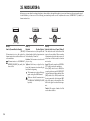
8. FILTER1-A
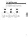
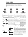
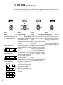
The filter section changes the tonal character of the oscillators by passing only the desired portion of the sound - either above (Low Pass), below
(High-Pass), or centered on (Band Pass) the cutoff frequency. The R3 has two filters (filter 1 and filter 2), and you can change their routing to
create more complex filter sounds. The filter 1 parameters are set in the 8. Filt1-A page and 9. Filt1-B page.
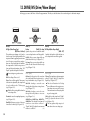
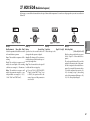
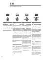
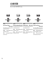
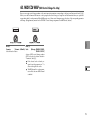
Knob [1]
Knob [2]
Knob [3]
Knob [4]
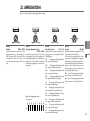
Cutoff1 (Filter1 Cutoff)
[000...127]
Sets the cutoff frequency.
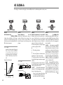
Increasing this value will raise the cutoff
frequency.
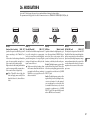
Reso1 (Filter1 Resonance)
[000...127]
Sets the resonance of the filter. This will
emphasize the overtones near the cutoff
frequency specified by “Cutoff1,” adding
a distinctive character to the sound. Increasing this value will increase the effect.
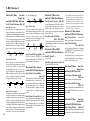
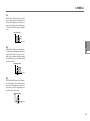
Since movement of the “Cutoff1” knob will
affect the overtones that are boosted by
resonance, it is best to adjust “Cutoff1” and
“Reso1” in conjunction with each other
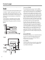
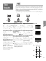
(☞Figure 8-1).
FiltBal1 (Filter1 Balance)
[LPF24…LPF12…HPF…BPF…THRU]
Selects the filter type. Intermediate settings
will produce a response that is between the
two filter types.
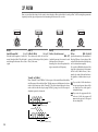
Routing1
[Single, Serial, Parallel, Indiv]
Specifies the routing (connection) between
filter 1 and filter 2.
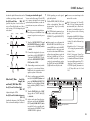
“Cutoff1” can be varied by time-variant change produced by EG1, by keyboard playing dynamics (velocity),
and by note location (keyboard tracking).
If the “Cutoff1” value is set too low,
the volume may be extremely low, or
you may hear no sound at all.
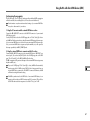
Figure 8-1: Filter1 Resonance
Depending on the cutoff frequency or
the input audio, increasing this value
may cause distortion.
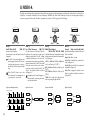
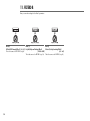
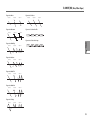
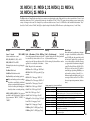
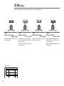
Figure 8-2: Serial
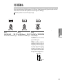
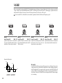
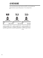
LPF12 (–12dB/oct), LPF24 (–24dB/oct):
Low Pass Filter (☞p.33 “LFP:”).
HPF (-12dB/oct): High Pass Filter (☞p.33
“HFP:”).
BPF (-12dB/oct): Band Pass Filter (☞p.33
“BFP:”).
THRU: The sound will output directly,
without passing through the filter.
Figure 8-3: Parallel
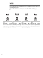
Single: Only filter 1 is used.
Serial: Filter 1 and filter 2 are connected in
series (☞Figure 8-2).
Parallel: Filter 1 and filter 2 are connected
in parallel (☞Figure 8-3).
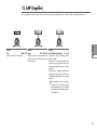
Indiv: Filter 1 is applied to oscillator 1, and
filter 2 is applied to oscillator 2 and noise
(☞Figure 8-4).
Figure 8-4: Indiv
The effect of resonance
OSC1
OSC1
OSC1
LPF
Filter1
OSC2
Filter1
Filter2
OSC2
HPF
Filter2
Noise
BPF
Low resonance value
32
Filter1
OSC2
High resonance value
Noise
Filter2
Noise