1
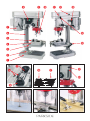
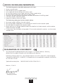
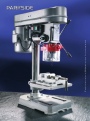
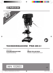
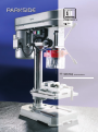
PTBM 350-13
2002
Operating
and safety instructions
Operating instructions
Kompernaß Handelsgesellschaft mbH
Burgstraße 21 · D-44867 Bochum (Germany)
Page
4- 7
BENCH DRILL PTBM 350-13
For drilling in wood, plastic and metal
Please read carefully through the following information concerning safety and proper use.
Before reading, fold out the page with the illustrations and make yourself familiar with all the
functions of the equipment. Please read the operating instructions
below and the
accompanying safety advice carefully. Use the equipment only as described and for the
indicated purposes. By doing this you will be able to work in complete safety and produce
better results.
Be careful to keep these advice notes and if necessary pass them on to a third party.
PROPER USE
The bench drill is intended for drilling in wood, plastic and metal using normal drill bits
up to a maximum diameter (ø) of 13 mm. Any other use of or modification to the
machine shall be considered as improper use and could give rise to serious danger.
SPECIFIC SAFETY ADVICE
In addition, you must also read the advice in the accompanying booklet called "Safety advice"
before using the equipment for the first time.
When you are using the bench drill always wear ear protectors and protective
glasses. We recommend that you wear robust anti–slip footwear, a working
apron or close-fitting clothing, If you have long hair you should wear some sort of hair protection
(such as a hair net, cap or headscarf) to ensure that your hair does not become trapped in moving
machine parts or twisted about the drill bit or chuck. Do not wear gloves when drilling.
Do not remove any mechanical or electrical safety devices.
Always check that all safety devices are attached and properly fixed in place.
Always check that the workpiece is firmly and securely clamped in place.
Never drill a workpiece whilst holding it in your hands.
Check that the chuck is properly attached.
Never clean or lubricate the bench drill when it is in motion.
Before adjusting, maintaining or repairing the drill, always remove the plug from the mains socket.
Use a hand brush to remove drilling swarf.
Ensure that you work safely by firmly fixing down the machine on to a working surface.
Always keep the drive/ belt cover closed to keep hands and fingers out.
Always use the key to open or close the drill chuck.
FEATURES OF THE PTBM 350-13
Base plate
3 column/base fixing screws
Drilling table
4 drill vice screws
Drill vice
Column
Motor unit
On/off switch
4
Chuck
Drill chuck guard
Drive/belt cover
Drive/belt cover handle *
Adjustment screw
Handle/spindle control
Table clamp screw
Contacts *
Drive (motor side)
Gears
Drive (spindle side)
Depth stop with scale
Adjustment nut
}
* = form and type may differ from that shown in the illustrations
TECHNICAL INFORMATION
Mains connection:
Current:
Nominal power:
Nom. speed, no load:
Power factor:
Duty cycle:
Drilling capacity:
Spindle travel:
Sound pressure level:
Vibration:
Weight:
230 V ~ 50 Hz
1.9 A
350 W
n0 1400 rpm (motor)
0.8
60 %
13 mm
50 mm
75 dB (A)
2.5 m/s2 (vibration)
approx. 19.5 kg
Spindle speed:
1.
2.
3.
4.
5.
Setting:
Setting:
Setting:
Setting:
Setting:
2600
1750
1250
0900
0600
rpm
rpm
rpm
rpm
rpm
We reserve the right to make technical modifications and changes without notice to the appearance of the equipment
in the course of further development.
ASSEMBLY
The bench drill is supplied ready to assemble. Remove the parts carefully from the packaging
and assemble the bench drill in the following manner:
Insert the column into the base plate and tighten the screws (3 column/base fixing screws ).
Place the drilling table on to the column and fix it in position using the table clamp screw .
Fix the drill vice (4 drill vice screws ) on to the drilling table .
Place the pre-assembled motor unit on to the column. The motor unit is attached by two
hexagonal socket screws on the right hand side.
5. Attach the three armed handle/spindle control in the rise and fall shaft.
6. Attach the chuck firmly to the drill spindle cone.
Attention: Clean the drill spindle cone thoroughly to remove all traces of grease.
1.
2.
3.
4.
SETTING UP THE MACHINE
Set the bench drill down on a firm surface and level it using a spirit level. We recommend that
the machine is bolted down on to the supporting surface. Please ensure that the base plate is
not subject to any additional forces as a result of being bolted down.
5
INSTALLATION AND FIRST USE
Check that the supply type, voltage and fuses comply with those specified for the machine.
First clean any anti-rust coating carefully from the parts. Then oil the column.
SWITCHING THE MACHINE ON AND OFF
Insert the plug into the mains socket and switch on the machine using the "I” button at the
on/off switch . To switch off use the “0” button.
CHECKING AND TENSIONING THE V-BELT
Open the drive/belt cover and check the V-belt tension. If it is correctly adjusted the V-belt
should be able to be moved approximately 1 cm in the middle between the two drive wheels.
Loosen the adjustment screw and press the motor unit backwards before retightening the
adjustment screw .
SETTING THE SPEED
The bench drill has 5 different speeds. The speed is set by simply repositioning the V-belt. To do
this open the drive/belt cover , loosen the adjustment screw and place the V-belt on the
relevant pair of drive wheels.
Note: The top pair give the highest speed; the bottom pair the lowest (
=2600, = 1750,
= 1250, = 900, = 600, see figure on page 3).
Then tension the V-belt as described in the section on “Tensioning the V-belt”.
Note: Inside the drive/belt cover there is a contact which must come together with an opposing
contact (see ) on the drive/belt casing base when the drive cover is closed. The motor can only
be restarted if the drive/belt cover is properly closed.
SETTING THE DRILLING TABLE
The drilling table can be adjusted by loosening the table clamp screw .
Set the table so that there is an adequate distance between the workpiece top surface
and the drill bit point.
The table can be swung to the side, e.g. when you wish to work on a tall workpiece that can be
attached directly to the base plate.
DEPTH STOP / DRILLING TO AN EXACT DEPTH
The depth stop with its scale allows you to drill to an exact depth.
First of all press lightly down on to the top of the workpiece surface using the handle and set
the drilling depth using the adjustment nut on the scale.
Note: Make sure that you take into account the length of the drill bit point (normally approx.
5 mm) when determining the appropriate setting for the cylindrical part of a drilled hole.
INCLINED DRILLING
The drilling table can be rotated to drill angle holes or to accommodate workpieces
with inclined ends. Release the hexagonal socket screws on the drilling table swivel joint.
Place the table at the required slope and retighten the hexagonal socket screws.
6
ADVICE ON DRILLING WORKPIECES
The following points should be observed at all times:
always use sharp tools
cool the drill bit with a suitable liquid
use a special drill bit for drilling into stainless steel
for very hard materials use a higher pressure at lower speed setting
for soft materials apply light pressure at a higher speed
Attention: too high a pressure overloads the motor and reduces the drilling speed
small drills require a high drill speed
larger drills require a lower drill speed
The following table gives further helpful advice:
the correct speed is different for each material
the cutting speed is dependent on the diameter of the drill and the rotation speed
the table gives the approximate rotation speed
please note that an average speed has been calculated for the listed materials and the rotation
speeds have been rounded
in some cases the calculated cutting speeds (CS) cannot be selected in practice - use the nearest
available value
Material
CS
Drill size
2
3
4
5
6
7
8
9
10
13
Wood, soft
300 rpm
max.
max.
max.
max.
max.
max.
max.
max.
max.
max.
Wood, medium
180 rpm
max.
max.
max.
max.
max.
max.
max.
max.
max.
max.
Aluminium "hard“
120 rpm
max.
max.
max.
max.
max.
max.
max.
max.
3800
2950
Wood “hard”, copper
60 rpm
max.
max.
max.
3800
3200
2700
2400
2100
1900
1500
Steel or sheet metal
35 rpm
max.
3700
2800
2250
1850
1600
1400
1250
1100
850
Aluminium “soft”
30 rpm
max.
3200
2400
1900
1600
1350
1200
1050
950
700
Structural steel
25 rpm
4000
2650
2000
1600
1300
1150
1000
900
800
600
Alloy steel
10 rpm
1600
1100
800
650
500
450
400
350
300
250
Stainless steel (VA steel)
10 rpm
1250
850
650
500
400
350
300
280
250
200
DECLARATION OF CONFORMITY
We, Kompernaß Handelsgesellschaft mbH, Burgstr. 21, D-44867 Bochum, Germany,
declare that this product complies with the following EU directives:
Machinery Directive (98/37 EC), Low Voltage Directive (73/23 EEC, 93/68 EEC), Electromagnetic
Compatibility (89/336 EEC, 93/68 EEC) in accordance with the applicable standards, and confirm
this with the CE mark.
Type/machine description:
PARKSIDE BENCH DRILL PTBM 350-13
Bochum, 31.08.02
Hans Kompernaß
- Managing Director -
7
WARRANTY
This piece of equipment is covered by a 36-month warranty as of the date of purchase. The equipment was produced with the greatest of
care and underwent thorough testing before delivery. In the unlikely event of detecting a functional defect, please return the equipment in its
original packaging with the proof of purchase (if available) to the closest service address.
Damage caused due to improper handling as well as regular wear of the parts are not covered by this warranty.
Beaver Electronic Services · The Lodge, Premier Business Park
Long Street, Walsall · West Midlands, WS2 9DY
Tel.: 0 19 22/72 55 54 · Fax: 0 19 22/72 54 17
WARRANTY
This piece of equipment is covered by a 36-month warranty as of the date of purchase. The equipment was produced with the greatest of
care and underwent thorough testing before delivery. In the unlikely event of detecting a functional defect, please return the equipment in its
original packaging with the proof of purchase (if available) to the closest service address.
Damage caused due to improper handling as well as regular wear of the parts are not covered by this warranty.
Irish Web Specialists
1 Verbena Avenue · Dublin 13
Tel.: 01/8 32 04 92 · Fax: 01/8 39 68 29
8
9
© graphic design, photos, translations by ORFGEN Marketing & Communication · Essen · Germany · www.orfgen-nm.de