1
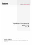
HOT WIRE TEST BOX
USER GUIDE
TM0098
WARNING
Please read this guide fully before attempting to operate the unit.
1.0
Introduction
This Guide describes the use of the Kidde Fire Protection Hot Wire Test Box (part number 1-53836K237) to test aspirating smoke detection systems. The unit provides 6V AC output from 220-240V AC
mains supply. High current at low voltage is passed through a cable in order to heat it, which causes
its insulation to burn giving off smoke. A timer is incorporated to provide a selectable burn period of
up to 3 minutes. The timer also helps to prevent the unit being inadvertently left on for an extended
period. The unit must never be left on unattended.
The unit must be operated for no more than three (3) minutes continuously and must be left off
immediately after operating for a period of at least six (6) minutes to allow it to cool.
The unit is protected against over-temperatures by a thermal switch. Once tripped, the thermal switch
will not allow operation for an extended period (up to an hour) regardless of power being present or
not. The thermal switch cannot be by-passed or reset manually.
TM0098
Page 1 of 4
Issue 1.00
2.0
Preparation and Precautions
When performing a hot wire test, ensure that all local standards, practices and regulations are
understood and have been adhered to where applicable. Also, ensure that the detection equipment
being proved/tested is isolated from both the local fire authority notification alerts and any
suppressant actioning devices. The hot wire test is intended to trigger a response from the High
Sensitivity Smoke Detectors under test. Ensure that the consequences of this activation are
understood and under control.
Precautions must also be taken to ensure that all personnel present are aware that the test is being
conducted and that those who are required to remain in the immediate vicinity of the test are suitably
attired for the smoke levels about to be created. Avoid inhaling the smoke plume as it contains
small quantities of hydrogen chloride.
The wire burn tests, particularly the 1m and 2 x 1m tests, produce sufficiently high temperatures to
generate small quantities of hydrogen chloride. However, test personnel are unlikely to be exposed
to concentrations of hydrogen chloride that exceed the Occupational Exposure Standard (OES) of
5ppm in a 15 minute period unless they are directly exposed to the smoke plume.
It is strongly recommended that personnel wear appropriate protective equipment such as an E1
respirator conforming to EN140 and goggles, without ventilation, conforming to EN166 in the following
situations:
•
•
Multiple tests are required
Personnel are within the immediate vicinity (e.g. 2m) of the smoke source
Due to the nature of hot wire tests there is a minor fire hazard. It is essential that an appropriate type
of fire extinguisher (e.g. C02 or Dry Powder) is available during the test.
It is the responsibility of the person carrying out the tests to ensure that the electrical equipment used
is maintained at all times for safety. In particular the correct fuse is fitted and that a power cord with
suitable local approvals is used. If in doubt, please seek guidance from a qualified electrician.
3.0
Equipment Set-Up
Ensure that the fuse fitted has the correct rating. If the fuse is not the correct rating for the supply
voltage in use then it must be replaced as follows:
1.
2.
3.
4.
Turn the unit off and disconnect the power supply cord
Eject the fuse drawer
Remove the existing fuse and replace with one of the correct rating
(See section 8)
Re-insert the fuse drawer
The timer must be in mode “C” with the scale set to “min” (minutes) and the scale showing from “0 to
3” (maximum of three minutes operation). The timer should appear like this:
TM0098
Page 2 of 4
Issue 1.00
It is recommended that the accuracy of the burn period is confirmed using a stopwatch with the red
indicator on the timer before conducting any live tests.
Applicable code wire burn recommendations:
•
•
4.0
BS6266:1992 recommends a burn time of 60 seconds for one metre wire lengths and 180
seconds for 2 metres
The NFPA 76 standard also recommends the same tests with an additional test with a burn time
of 60s using 2 x 1m wires connected in parallel.
Operation
a) Connect the IDE power cable (supplied) to the power input socket at the rear of the unit.
b) Switch on using the rocker switch above the power input socket. This will illuminate red when in
the “on” position. The green “Power” indicator on the timer will illuminate continuously.
c) Set the timer to the required test period.
d) Press the green push-button switch to the left of the timer. The red “Out” indicator will illuminate
continuously and the green “Power” indicator will flash. 6V AC will be delivered to the two screw
terminals on the front of the unit.
e) At the end of the time period, the “Out” indicator goes out and the green ”Power” indicator will
become steady.
f)
To repeat the process press the green push-button switch again, having set a different test period
if required.
g) On completion of the tests, switch the unit off using the rocker switch above the power input
socket and remove the power cable.
5.0
Preparation and Connection of the Test Wire
The test wire samples should be carefully measured and cut to the required length. The ends should
be stripped at approximately 15mm using a suitable tool. If in doubt, please seek guidance from a
qualified electrician. Only use the recommended test wire. Under no circumstances should
test wires be shorter than 60cm or 2x1m in parallel. This is likely to age (or blow) the inlet fuse
and may cause damage to the unit.
Ensure that no power is connected to the Test Box. Insert the test wire between the output terminals
and lay it on a supporting non-combustible platform. It is important to ensure that there are no cross
overs of the wire. It may be helpful to first coil the wire using a pen or pencil as a temporary former
and then lay it out. Alternatively, an arrangement to support the wire may be used with the precaution
of a fire blanket positioned beneath the wire. If the equipment is in a high airflow area then it may be
required to shield the wire from the airflow. At no time is it appropriate to open the Test Box.
There are no user-serviceable parts inside.
6.0
Smoke Test
Ensure that the local fire panel is isolated from the external fire reporting equipment and that any
automatic extinguishing or suppressant systems are similarly isolated. Connect power to the Test
Box and press the green push button switch. At this point, 6V AC is applied across the test wire, the
red “Out” indicator will illuminate continuously and the green “Power” indicator will flash. The test wire
will become hot and a quantity of smoke will be generated. The test wire becomes very hot during
the test and will cause burns if in contact with skin. Care must be taken throughout this test
process to protect both personnel and property from the hot wire.
TM0098
Page 3 of 4
Issue 1.00
The current to the wire is turned off automatically after the set period is complete. Smoke will have
been generated and the time for it to be detected should be recorded to ensure that transport and
alarm times are within the local regulatory requirements.
7.
References
Note that appropriate guidance should be sought from all local and applicable standards and
regulations such as:
•
•
•
•
•
BS5389 Part1: 2002
BS6266:1992
BS6266:2002 (which cross references to the BFPSA Code of Practice)
NFPA 76 : 2002
BFPSA Code of Practice for Category 1 Aspirating Smoke Detection Systems, Appendix A This
Appendix is published on the BFPSA (British Fire Protection Systems Association) website at
www.bfpsa.org.uk.
8.
Specifications
Hot Wire Test Box
Part Number:
Voltage Input:
Input Rating:
Fuse:
Output:
Operating Time:
Ingress Protection:
1-53836-K237
220-240V AC, 50Hz
1.6A @ 240V AC, 50Hz
220-240V AC, (T) (Anti-surge) 1.6A
6V AC nominal, 20A
Maximum on time: 3 minutes (180 seconds). Minimum off time between
tests: 6 minutes (360 seconds)
IP 30
Indoor use only. This product is not to be used in the presence of moisture.
Wire
Part Number:
Description:
9.
1-21888-K033
100 metres 10/0.1 mm strands insulated with PVC to a radial thickness of
0.3mm and the cross sectional area of the conductor being 0.078 mm².
Compliance
Safety:
EMC:
TM0098
EN 61558-1: 1997 Safety of power transformers, power supply units and
similar
EN61558-2-6: 1997 Particular requirements for safety isolating transformers
for general use
EN 50081-1 EMC-Generic Emissions
EN 50082-1 EMC- Generic Immunity
FCC Part 15 Class A Emissions
Page 4 of 4
Issue 1.00