1
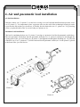
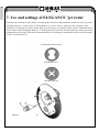
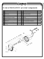
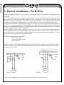
EN
JET SWIM ELEGANCE 70
INSTALLATION
AND
USER GUIDE
i
Read the instructions
EN
1. Installation mounting
By purchaising the ELEGANCE device, you obtained a high-quality product that will help you to enjoy
the time spent in your pool.
The ‘jet swim’ device, ELEGANCE is delivere, with and engine with inputs of 2,2kW. The electric pump
should be installed as close as possible to the pool in order to reach the maximum input and to reduce loss
caused by the friction. The original diameters of the accessories from the PVC materials delivered with
the installation should always be respected. We do not recommend to place the pump further than 15 m from
the pool. Pumps being the part of this device don’t have a self-suction function. It is necessary to install them
under the water level. The technology device area must be aired sufficiently, use a fan if needed, to prevent
water condensation. You can ensure the correct functioning of the device by respecting these rules.
2. Mounting the ‘jet swim’ device
During the installation of the’ jet swim’ body, please bear in mind that it must be placed in the position
indicated in the picture 1. Displacement of a 75mm diameter and a suction of a 90mm diameter must be
installed in the vertical position that the side of the displacement is higher than the side of the suction
(90 mm diameter) see picture 1. The ‘jet swim’ device must be placed in a way that the centre of the jet will
be approximately 30cm under the water level. (see picture 1). You must follow and keep these instructions
and mount correctly the device to ensure the right operating of the ‘jet swim’.
WATER LEVEL
DISPLACEMENT
30 cm
INTAKE
OK
NO
NO
Picture 1
2
EN
INSTALLATION IN CONCRETE
SWIMMING POOL
INSTALLATION IN CONCRETE
SWIMMING POOL WITH FOIL
CONCRETE
POOL
CONCRETE
FOIL
SEALING No. 18
(another sealing may be from other
side of foil)
Picture 2a
Picture 2b
INSTALLATION IN PANEL
OR SHEETMETAL SWIMMING POOL
WITH FOIL
INSTALLATION
IN PREFABRICATED (LAMINATE
OR POLYPROPYLEN) SWIMMING POOL
PANEL OR SHEETMETAL
APERTURE Ø 270mm
POOL SIDE
FOIL
Picture 2c
Picture 2d
3
EN
3. Jet swim body installation
3.1 Installation of jet swim device body in concrete ground
Stick hoses (no. 21 picture 3) on the ‘jet swim’ body (no. 20 picture 3) and connect them into the technologic
device area (basin). Protect the hose endings against the concrete. Carry out the ‘jet swim’ body installation
no. picture 20 3 as indicated in the picture 2a into the hole made in a concrete wall or into the boarding for
concreting without a flange or padding. If the body is fixed to the wall, follow the instructions in the article
4 and install the pneumatic and air connection.
3.2 Installation of jet swim device body in concrete pools with foil
While mounting the ‘jet swim’ body into the walls of a concrete pool with foil, please follow the instruction
written in the chapter no. 2 and 3. You can start to mount the padding and the ‘jet swim’ flange picture 2b.
into the pool while fixing the ‘jet swim’ body into the wall of a pool. 2b.
Tighten the padding (no. 18 in the picture 3) into the ‘jet swim’ body (no. 20 in the picture 3) by 2 screws
(no. 19 in the picture 3) and bear in mind that the pool foil can be situated between two padding (picture 2b).
Fix the flange in the end (no. 17 in the picture 3) and tighten the screws (no. 16 in the picture 3), after this
step is done, cut the foil from the inside part of the flange.
During the installation of the air and pneumatic lead, take the steps according to the article 4.
3.3 Installation of jet swim device body in panel or sheetmetal pool with foil
Prepare the opening of 270 mm diameter in the wall pool in a way that the centre of a jet is approximately
30cm under the water level as described in the article 2 and picture 1. Place the ‘jet swim’ body no.20 picture
3 from the inside part of the pool into the prepared opening. Fix the body by 8 self-drilling screws no. 19
picture 3 into the wall of the pool as described in the picture 2c.
Tighten the padding (no. 18 in the picture 3) to the ‘jet swim’ body (no. 20 in the picture 3) by 2 screws
(no. 19 in the picture 3) After the installation of the foil, fix the flange (no. 17 in the picture 3) and tighten
the screws (no. 16 in the picture 3), then cut the foil from the inside part of the flange.
During the installation of the air and pneumatic lead, take the steps according to the article 4.
3.4 Installation of jet swim device body in prefabricated (laminate or polypropylen) pool
Prepare the opening of 230 mm diameter in the wall pool in a way that the centre of a jet is approximately
30cm under the water level as described in the article 2 and picture 1.
Stick the padding (no. 18 in the picture 3) from the inside part of the pool wall and prepare openings for
16 screws of the flange (no. 16 picture 3).
Prepare the ‘jet swim’ body (no. 20 picture 3) from the inside part of the pool and tighten the flange
(no. 17 in the picture 3) by screws (no. 16 in the picture 3) from the inside part as described in the picture 2d.
During the installation of the air and pneumatic lead, take the steps according to the article 4.
4
EN
4. Air and pneumatic lead installation
Air lead installation:
Stick the reducer (no. 22 picture 3) on the hose serving as an air lead and install the back-pressure valve
(no. 23 picture 3). I tis important to place a pressure-valve on the wall of the technologic housing in order
to prevent the dirt suction (see picture no. 6) Finally, fix the elastic tube (no. 13, picture no. 3) by pressing
it into a jet placed inside of the ‘jet swim’ body (see picture no. 4).
Pneumatic lead installation:
This lead is containing the hose (no. 21 picture 3) serving as a protective lead for the pneumatic switch hose.
Place the pneumatic switch hose into the pneumatic lead (hose no. 21 picture 2) and put its end through the
opening place in the ‘jet swim’ body (no. 20 picture 3) and tightened it through the brushing (no. 14). The end
of the hose (no. 2 in 13, picture no. 3) will be connected to the pneumatic switch (no. 1 in the picture 3) placed
in the front of the ‘jet swim’ device.
Picture 3
Picture 4
5
EN
5. Fitting of the ‘jet swim’ front cover
The complete front cover is delivered mounted and contains parts no. 1 to 12 (see picture 3). The exception
is the transparent pneumatic hose (no. 2) being already a part of the ‘jet swim’ body (see picture 4).
Follow these steps while mounting the front cover:
- Connect the hose no. 2, pull it up to the horn of the pneumatic switch (no. 1 in the picture 3) 3).
- Connect the hose no. 13, insert it into the jet on the front cover.
- Connect the complete front cover to the ‘jet swim’ body and make sure that the ring (no. 12) is inserted
in the nozzle of the displacement opening (75 mm diameter).
- Tighten all four screws (no. 3 in the picture 3) While they are fitted tightly, the front cover is ready to use.
6
EN
6. Minimum requirements for space and device
installation
Before the initiation of the installation, it is necessary to consider the technological housing (basin) proportions
where you want to place the ‘jet swim’. Make sure in advance that you won’t have any problems due to
the lack of space while mounting the pump.
Minimum recommended proportions needed for the device installation of the technological housing, see
picture 5 plus table.
width (mm)
750
length A (mm)
1420
high B (mm)
900
VENTILATION
WATER LEVEL
AIR
SUCTION
30 cm
INTO EL. SWITCHING
Picture 5
7
EN
7. Use and settings of ELEGANCE ‘jet swim’
from the water current or water with air created by this unit. Press the pneumatic switch to set the ‘jet swim’
from the pool (no. 1 in the picture 6). The turned on ‘jet swim’ force is: only the water current or water
with the air. It depends on setting of the front jets (see picture 6). Only the water current: Maximum water
flow is achieved by turning the inside jet 2 in the picture 6) to the left. You will reduce the water current by
turning the jet to the right. The water current with the air: For setting or reducing the air flow, turn the outside
jet (no. 3 in the picture 6).
JET SWIM NOZZLE DETAIL
MAXIMUM FLOW
MANIMUM FLOW
Picture 6
8
EN
8. List of ELEGANCE ‘jet swim’ components
no.
1
2
3
4
5
6
7
8
9
10
11
12
description
pneumatic switch
pneumatic hose
front screw
‘jet swim’ front cover
external ball
jet regulating the air supply
supporting ring
jet regulating the water supply
inside ball
jet screw – self – drilling
jet application
O - ring
amount
1 piece
7m
4 pieces
1 piece
1 piece
1 piece
1 piece
1 piece
1 piece
3 pieces
1 piece
1 piece
no.
13
14
15
16
17
18
19
20
21
22
23
Picture 7
9
description
elastic hose (air)
pneumatic hose reducer
O-ring of the reducer
screws of the flange
flange
padding
‘jet swim’ body screw – self-drilling
‘jet swim’ body
air and pneumatic leading hose
reducer 20 x ½ ‘’ ex
suction air back-pressure valve
amount
1 piece
1 piece
1 piece
16 pieces
1 piece
2 pieces
4 pieces
1 piece
2x1m
1 piece
1 piece
EN
9. Electric installation - WARNING
Electric installation should be carried out by an authorized engineer in conformity with general valid
standards.
The tension of the electric supply must correspond to the data on the tag installed on every device. All metal
parts of the device must be connected (earthed). Electric characteristic of circuit breakers and their rules
must be in accordance with those, valid with the engine that should be protected with supposed operating
conditions. All instructions implemented by the producer must be respected (see indication on the tag).
In case of the installation with a three-phase engine, connecting parts in the terminal board must be installed
correctly (i.e. Y connection) while switching off the engine. Input and output conductors from the distribution
box must be led through bushings preventing humidity and dirt intrusion into the distribution box. Conductors
will have appropriate terminals for connection.
Electro-pneumatic switch must be installed on the dry place, above the water level in the distance not
exceeding further than 7m from the pneumatic switch installed on the ‘jet swim’ front. The pneumatic hose
(no. 2 in the picture 3) is designated for connecting to the electro-pneumatic switch (switchgear). It is very
important to check if the hose is not bended anywhere.
Electro-pneumatic panel is composed of:
- 1 motor protection
- 1 electro-pneumatic switch
- 1 operating fuse
All these components should be installed in the waterproof plastic box with the rate of protection of IP55.
Note: You will receive more information about the installation, protection and maintenance from the electropneumatic board manual.
ENGINE
ENGINE
Picture 8
Picture 9
FM - control fuse, DM - heat engine protectione, I.N. - electropneumatic switch unit, C - clamper
10
EN
10. ELEGANCE ‘jet swim’ pump
The ELEGANCE ‘jet swim’ is using the STP-2200 pump of the three-phase type adjusted on 230/400V with
the electric input of 2,2kW. For size see the picture 10 power characteristic picture 11.
Picture 10
Picture
11
11
EN
Conditions of guarantee
Conditions of guarantee abide by the trading and guarantee conditions of your supplier.
Secure disposal of the product after the lifetime expiry
After the lifetime expiry, ensure its ecologic disposal made by a skilled company
Complaints and customer service
Complaints abide by the appropriate consumer protection rights. In the event of unrecoverable effect
address the written complaint to your supplier.
Date................................................................
Supplier
12