1
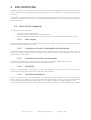
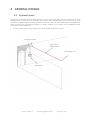
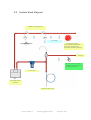
Pipe Installation Manual
ASD 1 & 2
Rev. 2
COPYRIGHT INFORMATION
ICAM Ltd Copyright 2007
This document may not be reproduced, in whole or in part, by any means without the prior permission of the
copyright owner.
Pipe Installation Manual V2
Content
1
2
INTRODUCTION .........................................................................................................2
AIR-SAMPLING...........................................................................................................3
2.1
3
Easy access........................................................................................................................ 3
Protection of Voids, Inaccessible and High Areas...................................................................... 3
Protection of hostile environments ......................................................................................... 3
Flexibility ........................................................................................................................... 3
Invisible installations............................................................................................................ 3
GENERAL DESIGN ......................................................................................................4
3.1
3.2
3.3
4
Uses of Air-sampling ................................................................................................................3
2.1.1
2.1.2
2.1.3
2.1.4
2.1.5
System layout .........................................................................................................................4
System block diagram..............................................................................................................5
Wide-bore Systems, Units & Accessories ....................................................................................6
3.3.1
3.3.2
3.3.3
3.3.4
3.3.5
3.3.6
Detector Units .................................................................................................................... 6
Pipe Sections and Fittings..................................................................................................... 7
Brackets ............................................................................................................................ 9
Condensation Trap ............................................................................................................ 10
Heater Element with Condensation Trap ............................................................................... 10
Filter Elements.................................................................................................................. 11
Detailed Design and Installation................................................................................. 12
4.1
The Design Process .................................................................................................................12
4.1.1
4.1.2
4.1.3
4.1.4
4.1.5
4.1.6
Requirements ................................................................................................................... 12
Activities .......................................................................................................................... 12
Physical Characteristics ...................................................................................................... 12
Environmental Conditions ................................................................................................... 12
Risk Assessment ............................................................................................................... 13
Location........................................................................................................................... 13
4.3.1
4.3.2
Response Times................................................................................................................ 16
Dilution............................................................................................................................ 17
4.2
4.3
4.3
Typical layouts of ASD1 & ASD 2 ...............................................................................................14
Response Times and Dilution ....................................................................................................15
Response Times and Dilution ....................................................................................................16
4.4
4.5
4.6
Commissioning an installation ...................................................................................................18
Rules of thumb........................................................................................................................19
Design for Still Air Environments or Secondary Sampling Systems .................................................20
4.6.1
4.6.2
General Still Air Design....................................................................................................... 20
Capillary Sampling............................................................................................................. 22
4.8.1
4.8.2
Sub-floors ........................................................................................................................ 24
Ceilings............................................................................................................................ 25
4.9.1
4.9.2
4.9.3
4.9.4
4.9.5
High Areas ....................................................................................................................... 26
Prisons ............................................................................................................................ 27
Elevators – machine rooms and shafts.................................................................................. 28
Smoke domes................................................................................................................... 29
Stables & Live Stock Areas.................................................................................................. 29
4.7
4.8
4.9
Design for layouts with Air Ducts or Primary Sampling Systems ....................................................23
Design for layouts with Sub-floors and ceiling voids.....................................................................24
Unusual Applications................................................................................................................26
Part No. 09-0003-12
ASD Pipe Installation Manual
1
Copyright C 2007
1 INTRODUCTION
This document is a guide for the installation of pipe-work for air-sampling systems. The pipe network is as
important as the detector itself and provides a means of obtaining a reliable and continuous sample of air to be
monitored.
The pipe work for air-sampling systems can vary greatly depending on the particular application. This manual,
therefore, gives overall guidelines that can be applied to any system but also a number of specialised set-ups are
described in more detail. These include:
Duct sampling
High or large area buildings
Prisons
Staircases
Stables and areas with live stock
When designing a sampling pipe network one needs to achieve an air sampling network design that offers sampling
hole (detector) area coverage that meets as a minimum the requirements for point type detectors.
This guide is intended to give general guidelines for installing air-sampling systems but in each case, the local
standards and codes of practice are to be taken into account. For reference, guidance on the design of systems
is given in BS 5839, BS 6266 (Code of Practice for Fire protection for Electronic Data Processing installations,
Appendix A of BS6266 gives a range of performance tests suitable for a wide variety of applications) and/or BFPSA
Code of Practice for Category 1 Aspirating Detection Systems..
Aspiration system designers must be familiar with the local standards.
It is strongly recommended that, before designing the pipe-work system, smoke tests be undertaken in
order to show the patterns of air movement within the areas to be protected. This is particularly important
in rooms with air-handling equipment. More details are given at relevant points throughout the text.
Finished installations must be subjected to System Performance Tests.
The various applicable tests can be found in the BFPSA Code of Practice for ASD’s.
Part No. 09-0003-12
ASD Pipe Installation Manual
2
Copyright C 2007
2 AIR-SAMPLING
ICAM offers wide bore air-sampling systems with both conventional and analogue addressable point detectors. Both
types of system have their specific applications ranging from simple duct detection to monitoring atria and many
other areas.
Air sampling is the technique where air is drawn through pipes from protected areas to a central unit, where the
actual smoke detector is situated. This is in contrast with traditional point detectors, where the unit is actually in
the protected area.
2.1
Uses of Air-sampling
Air sampling offers many benefits:
Central service using pipe network.
Protection of voids, inaccessible, high and hostile areas.
Invisible installations using micro-bore pipes or capillary tube sampling within ceilings or below floors.
2.1.1
Easy access
Only the control unit (placed at a convenient location) requires servicing. The alternative is servicing tens of point
detectors, located in many different rooms.
2.1.2
Protection of Voids, Inaccessible and High Areas
Air samplers are ideal for such situations. Sampling points are installed once and then require no further service. By
contrast, point detectors [being located in the actual area], may be difficult or even impossible to test, service or
update because of the location.
2.1.3
Protection of hostile environments
Air samplers are ideal for areas with high level of dust and dirt as well where high humidity is present.
Filters, heaters and water traps provide solutions in these hostile areas.
2.1.4
Flexibility
Further to the advantages of sampling, the systems also benefit from all the features of the panel they are
connected to like extra delays, double knock and other smart algorithms.
2.1.5
Invisible installations
Often, in situations such as historical buildings, it is important to keep the installation from interfering with the
décor or structure. The ASD can use on the large-bore pipes capillary tubes, which are, not only small in diameter,
but are also extremely flexible. This enables pipe runs to be hidden in coving or a similarly unobtrusive place.
The majority of the pipes are above the ceiling or beneath the floor and only the end of the capillary tube is visible.
Part No. 09-0003-12
ASD Pipe Installation Manual
3
Copyright C 2007
3 GENERAL DESIGN
3.1
System layout
The majority of aspirated smoke detection systems are used in one of two ways. The first is when there is an air
handling system in the area to be protected. The second is when sampling points are used where one would
normally use standard detectors, mainly in still air environments. There are also specific layouts and applications,
some of which will be covered later although it is always necessary to look closely at any installation because
almost every location is different.
A classic system layout is shown below. This is the most basic of wide-bore set-ups.
Mounting brackets
Pipe(s) with
sampling holes
End cap with hole
ASD detector
Part No. 09-0003-12
ASD Pipe Installation Manual
4
Copyright C 2007
3.2
System block diagram
Capillary sampling points
Air intake
Air sampling points
Hole diameter and location
along the pipes through
PipeTracer software package
End cap
Air flow sensors monitor
blockages and fractures of
the individual pipes
In-line filter
Aspirated Smoke
Detector
Heater & water trap
Part No. 09-0003-12
ASD Pipe Installation Manual
5
Copyright C 2007
3.3
Wide-bore Systems, Units & Accessories
ASD (Aspirated Smoke Detector) air-sampling systems have one or 2 wide-bore rigid pipe outlets. It is
recommended that ABS pipe is used due to its strength and heat resistant properties. These pipes can be hung
under or in the ceiling of the area to be protected, in voids, shafts etc. Air is drawn in from the protected area,
through a number of small holes in the sidewall of the pipes.
The red pipes carrying the warning ‘ASPIRATING SMOKE DETECTION SYSTEM – DO NOT PAINT OR OBSTRUCT
INLETS’ are preferred. It may in certain cases be favoured to use standard plastic conduit to avoid attention and
tampering. At all times make sure the installation conforms to local regulations and is approved by local authorities.
.
NOTE: Pipes should be glued together to avoid separation or leaks but the pipes must not be glued
into the unit itself. Removable unions should be used where maintenance may require pipes to be
taken apart or removed.
3.3.1
Detector Units
ASD 1 & 2
One and 2 pipe units with traditional point detectors, conventional and /or analogue addressable detectors
Part No. 09-0003-12
ASD Pipe Installation Manual
6
Copyright C 2007
3.3.2
Pipe Sections and Fittings
Straight pipe sections
Pipes are made of ABS and come in lengths of 3 meter.
Straight union
Connects the pipes together. Make sure pipes and unions are always glued together.
T-union
Allows to T-off to one or two sections of pipes.
Removable Union
Use when a connection is not to be permanent. I.e. when section of pipe needs to removed for maintenance
of equipment like with Air Handling Units
Sticker to identify the sampling hole
Part No. 09-0003-12
ASD Pipe Installation Manual
7
Copyright C 2007
End caps, (typically with a 6mm hole)
Used at the end of a pipe run. Diameter of the hole determines airflow and is determined in the PipeTracer
program.
Bends (45º and 90º
Always use slow bends as the minimise pressure loss in the system.
Capillary tubes and sampling points
Capillary tubes and associated sampling points allow sampling at a specific location away from the pipes.
Used with i.e. with false ceilings, cabinets etc.
Part No. 09-0003-12
ASD Pipe Installation Manual
8
Copyright C 2007
3.3.3
Brackets
Channel Bracket
Used to click on a channel.
Studding Bracket
Used to mount on a treaded rod.
Wall Bracket
Used to be fixed directly to a wall or ceiling.
Closed Pipe Clip
Used to be fixed directly to a wall or ceiling.
Open Pipe Clip
Used to be fixed directly to a wall or ceiling.
Part No. 09-0003-12
ASD Pipe Installation Manual
9
Copyright C 2007
3.3.4
Condensation Trap
If the air being sampled is hot and humid and there is the possibility of a temperature change causing
condensation to form in the sampling pipe, a condensation trap can be used to avoid the moisture reaching the
detector. As shown in the picture below, a micro-bore pipe is connected to an end cap which forms the trap. The
moisture will collect in the pipe but run down and eventually out of the system prior to entering the detector. Make
sure the pipe(s) are angled down towards the water trap and then onto a local drain, or water tight container that
should be changed regularly.
.
3.3.5
Heater Element with Condensation Trap
When cold air is returned as in cold stores it is important to provide heating elements (30 W) to avoid icing of the
units (see section freezers for more details). Heaters always need to be used in conjunction with water traps.
Make sure the pipe(s) are angled down towards the water trap and then onto a local drain, or water tight container
that should be changed regularly.
Part No. 09-0003-12
ASD Pipe Installation Manual
10
Copyright C 2007
3.3.6
Filter Elements
Wide bore filter
The Filter, 02-FLU1, is used as a pre-filter where aspirating systems are installed to monitor excessively dusty or
damp environments. Aspirating systems are ideally suited to harsh environments where conventional smoke
detectors would fail to operate when subjected to water spray or excessive dust. The tubing network can be kept
clean with periodic manual or automatic compressed air purges and the air sampling detector can be protected
with filter+. The filter element has a large surface area to minimise the service replacement intervals. The particle
sizes trapped by the element are 30 m and above as standard with other pore sizes available.
Smoke particles, having a typical size of 0.01-2.5 µm, will pass through the dust filter and be detected by the laser
detector.
End of line sintered filter for Capillary tubes
It is recommended that a sintered end of line filter is used at the end of every capillary tube. This will ensure that
the airflow is not impeded by blockages such as insects.
A sampling point like the one below can also be used to provide both a sturdy and safe end point and also an
aesthetically pleasing one. These can be screwed to walls or ceilings and also incorporate filters.
Part No. 09-0003-12
ASD Pipe Installation Manual
11
Copyright C 2007
4 Detailed Design and Installation
4.1
The Design Process
When designing the actual sampling pipe network there are many factors that need to be considered. The site
must be carefully surveyed and as much information as possible should be gathered. The ASD Planning and
Overview Form and the ASD Design Form from the BFPSA COP come in handy at this stage.
4.1.1
Requirements
It is critical to define requirements and expectations at an early stage.
Consider carefully the following points:
What are the end users expectations?
What are the risks?
What sensitivity is required from the system?
What area is to be covered?
What response times are required?
Without concrete answers to the above there is the hazard of a badly performing system and an unsatisfied
customer!
Once these have been decided, the type of situation can be looked at.
4.1.2
Activities
The types of activities that take place within the space are very important. A public area of a particular shape could
well have different system requirements than a private place of a similar shape. Some different examples are
outlined below.
Other information such as the expected hours of operation, whether the area is manned or unmanned and whether
any pollution or dirty air is present should also be taken into account.
4.1.3
Physical Characteristics
Once the general installation type has been considered, the physical characteristics of the space are looked at and
the following questions should be asked.
Is it a room, void, cabinet or enclosure?
Are there any floor or ceiling voids and, if so, how are they divided, are there any ducts, what are these
used for and are there any services already present?
What are the exact measurements of the space?
What materials have been used and are there any areas where the network has to avoid?
Are there any existing fire protection systems and where are they situated?
Does the fire load change regularly?
4.1.4
Environmental Conditions
The environment within the space can have a very significant bearing on which sampling method should be used to
protect it. As already mentioned, the smoke tests are vital in gathering this information. This can tell you the
patterns of air movement, the rate of circulation and whether the airflow is static at any point. Other considerations
include:
If fresh air is introduced, at what rate and in what quantity?
What is the temperature and relative humidity and are these constant or variable?
Are there any activities that may produce smoke, dust, steam or flames and how often does this occur?
Part No. 09-0003-12
ASD Pipe Installation Manual
12
Copyright C 2007
4.1.5
Risk Assessment
With any installation it is likely that some areas require more protection than others. This could be because of
expensive equipment or a particularly vulnerable area such as a store for flammable materials. These more
susceptible areas must be considered along with any structural hazards such as synthetic materials and foams or
soft wood partitioning.
4.1.6
Location
There are also factors to consider when deciding on the position at which the detector itself will be situated. The
main aim when positioning the detector unit is to try to ensure a balanced system. This means that the pipes
should be kept at similar lengths. It is also important to try and keep response times and dilution to a minimum.
These are two very important factors in air-sampling and are discussed in more detail in the following section.
The unit requires a power supply and access will be required for maintenance. There may also be aesthetic reasons
why a particular position is not suitable.
Part No. 09-0003-12
ASD Pipe Installation Manual
13
Copyright C 2007
4.2
Typical layouts of ASD1 & ASD 2
The following layouts, pipe lengths and number of holes are according the VdS test results and
approvals
Using ASD1 in the type 1 layout pipe run can go up to 50 m
The amount of holes in the pipe is depending on the detector that is used.
See below for details.
APOLLO
DETECTOMAT
GE SECURITY
HOCHIKI
SYSTEM SENSOR
Part No. 09-0003-12
S65 Optical
XP95 Optical
DISCOVERY Optical
CT 3000 D
PL 3200 O
PL 3300 O
DP 721I
DP 2061
DP 951
SLR-E3
ALG-E
2251EM - standard
2251EM - high
ECO 1003
1
2
1
1
1
1
3
6
2
1
1
1
2
2
x
x
x
x
x
x
x
x
x
x
x
x
x
x
8mm End Hole
8mm End Hole
8mm End Hole
8mm End Hole
8mm End Hole
8mm End Hole
4mm Holes
4mm Holes
8mm End Hole
8mm End Hole
8mm End Hole
8mm End Hole
5mm Holes
5mm Holes
ASD Pipe Installation Manual
14
Copyright C 2007
When using ASD2 in the type 1 layout both pipe runs can go up to 50 m
The amount of holes in the pipe is depending on the detector that is used.
See below for details.
APOLLO
DETECTOMAT
GE SECURITY
HOCHIKI
SYSTEM SENSOR
S65 Optical
XP95 Optical
DISCOVERY Optical
CT 3000 D
PL 3200 O
PL 3300 O
DP 721I
DP 2061
DP 951
SLR-E3
ALG-E
2251EM - standard
2251EM - high
ECO 1003
1
2
1
1
1
1
3
6
2
1
1
1
2
2
Pipe 1
x 8mm End Hole
x 8mm End Hole
x 8mm End Hole
x 8mm End Hole
x 8mm End Hole
x 8mm End Hole
x 4mm Holes
x 4mm Holes
x 8mm End Hole
x 8mm End Hole
x 8mm End Hole
x 8mm End Hole
x 5mm Holes
x 5mm Holes
1
2
1
1
1
1
3
6
2
1
1
1
2
2
Pipe 2
x 8mm End Hole
x 8mm End Hole
x 8mm End Hole
x 8mm End Hole
x 8mm End Hole
x 8mm End Hole
x 4mm Holes
x 4mm Holes
x 8mm End Hole
x 8mm End Hole
x 8mm End Hole
x 8mm End Hole
x 5mm Holes
x 5mm Holes
Please also make sure you use the correct baffles.
Baffles are plastic inserts that help to maximise the aspirated air flow trough the detectors.
4.3
Part No. 09-0003-12
ASD Pipe Installation Manual
15
Copyright C 2007
Response Times and Dilution
Dilution and response times are two factors that can cause the system to under-perform.
4.3.1
Response Times
The transport time of a system is the time taken for a smoke particle to travel from the sampling point to the
detector.
The response time is the transport time plus any delays set in the detector. In any situation where an air-sampling
system is being used, early detection is vital and therefore response times are kept to a minimum.
The simplest method of achieving this is to keep pipe lengths to a minimum.
Example: The advantage of multiple sampling pipes.
This room has a single sampling pipe that provides detection for the whole room.
The same room with two sampling pipes:
Part No. 09-0003-12
ASD Pipe Installation Manual
16
Copyright C 2007
4.3.2
Dilution
As the name suggests, dilution is the process of lessening the concentration of smoke particles as the sample is
sucked towards the detector.
For example:
There is a sampling pipe measuring 30 meters. It has sampling holes every 10 meters, giving 4 sampling holes
including the end cap. It can be assumed in this simplified case that the sampling holes let in approximately the
same amount of air as each other.
A smoke source of 4% obscuration/meter is introduced at the far end of the pipe. No other smoke is entering any
of the other sampling holes. As the smoke passes each hole, it is added to with clean air. When the sample reaches
the detector it is now at 1% obscuration/meter or 1/4th of its starting density. Therefore if the detector alarms at
1% obsc/m, the smoke outside the hole must exceed 4% obsc/m to sound the alarm.
It is the case, therefore, that the longer the pipe and the greater the number of sampling holes, the more
susceptible the system will be to dilution.
It is wise to work on a worst case principle in these situations.
Actuality the calculation of dilution is not as straightforward as above and more factors are involved. Each system
will have different characteristics meaning precise calculation is extremely complicated.
Lower
density to
detector
Smoke in
high density
Clean Air
Part No. 09-0003-12
ASD Pipe Installation Manual
17
Copyright C 2007
4.4
Commissioning an installation
It is necessary to carry out an inspection of the completed installation to check for quality of workmanship, correct
use of materials and that the installation fully complies with the correct National Standard that the intended ASD
systems have been installed to.
After the wide bore pipe network has been installed, before the end cap is put on and before the pipes are
attached to the unit it is necessary to clean the internal pipe system to remove unwanted swarf debris and dust
which could affect the ASD system performance. This may be done by either a positive blowing-out of the pipe
network with compressed air or by the use of a vacuum cleaner.
Commissioning tests should be carried out depending on the ASD system application and only when the building is
in its normal, intended running state. Appropriate commissioning tests should also be performed after modifications
and/or additions to the ASD system.
BFPSA COP presents a performance test according to the response of a Class C system
Always provide for an easy access test hole at the furthest end of all pipe
runs!
Easy access
test point
Part No. 09-0003-12
ASD Pipe Installation Manual
18
Copyright C 2007
4.5
Rules of thumb
When designing aspiration systems it is good workmanship to observe the rules of thumb listed below
•
•
•
•
•
•
•
•
•
Spacing requirements not to exceed point detector spacing.
Joints shall be permanently bonded.
If the sensor is mounted outside the protected area, return the exhaust back to the protected area.
Do not run pipes in areas with different air pressure
ABS or PVC Pipe to comply with local quality standards.
Power supply to comply with local requirements
Length of pipe:
shorter pipe length
shorter response times.
Share per hole:
shorter pipes = better hole share, i.e. the difference between the flows into the first and last
sampling points are reduced as the pipe gets shorter.
Number of Bends:
less bends less travel time and better flow.
In general
Only smoke tests will show exact smoke path, helping the designer to correctly locate pipes and sampling
holes
Part No. 09-0003-12
ASD Pipe Installation Manual
19
Copyright C 2007
4.6
Design for Still Air Environments or Secondary Sampling
Systems
4.6.1
General Still Air Design
Still air environments do not have a pattern for the air movement. This means that the sampling points must give
general cover across the whole expanse of the area. The coverage and layout will closely follow the guidelines for
traditional point detectors.
Failure to design and install a properly thought out pipe network can result in slow response times thereby
negating some of the early warning ability of the system. The way to avoid any problems occurring is to ensure
that all pipes are a similar, or preferably equal, length.
Typical examples:
Prisons, atria, ducts, elevator shafts, escalators, display cabinets, stables and residences.
Design Criterion:
Design to BS EN 54 (BS 5839 Pt.1) that states that no point in the room should be further away from a
detector than 7.5 meters.
Each traditional detector should cover an area no greater than 100 square meters.
Keep the pipe lengths as similar as possible to ensure a balanced system and minimal response times.
Distance A: maximum 5 m
Distance B: maximum 10 m
Part No. 09-0003-12
ASD Pipe Installation Manual
20
Copyright C 2007
This layout is showing point detectors in a simple 400 square meter building
Layouts showing a sampling system in a simple 400 square meter building. A pipe covers the same area. The red
dots show the position of the sampling holes which are identical to the position of the point detectors above.
The width of the pipes and the detector in the picture are enlarged in order to make them clearly visible.
Always use a grid overlay to determine the correct positioning of the pipe network and ensuring full
area covering.
Wrong positioning as not all of the area is covered
Correct positioning as all of the area is covered
Part No. 09-0003-12
ASD Pipe Installation Manual
21
Copyright C 2007
4.6.2
Capillary Sampling
Short lengths of small diameter flexible pipe may be spurred off from the main wide-bore pipe. These capillaries
should have an internal diameter of no less than 7mm and can be up to 1,5 meters length. To create the sampling
point, a sampling point assembly should be used.
Capillary Sampling is particularly useful for concealed sampling points
For aesthetic reasons, the sampling points may need to be as unobtrusive as possible. Often the main wide-bore
pipe runs through a ceiling void, with capillary sample pipes taken off through the ceiling. The sampling holes are
made using a sampling point assembly. This is a simple assembly into which the capillary tube fits. If small insects
or dirt is expected a sintered end of line filter can be mounted to the sampling point itself.
Capillary tubes
Ceiling panel or tile
Concealed
Sampling point fitting
Part No. 09-0003-12
Sampling point fitting
ASD Pipe Installation Manual
22
Copyright C 2007
4.7
Design for layouts with Air Ducts or Primary Sampling
Systems
Return Air, Exhaust Air and other Air Conditioning Ducts are typically regions of very high airflow. Providing
Aspirated Air Sampling Detection Systems in these areas can be very beneficial. Large areas can be protected with
relatively few detectors and also with minimal intrusion into the protected area thereby reducing the costs of
installation and maintenance involved. This method is also unobtrusive which can be an important factor in
deciding the type of installation for architects and end users.
Normally Aspirated Air Sampling Systems would be placed in air return ducts as supply air ducts can be filtered or
be contaminated with makeup air possibly making the system ineffectual and the cause of nuisance alarms.
If the ventilation system does not operate permanently it may be necessary to install a secondary system to sample
within the protected area during the times that the Air Conditioning plant is shut down. In some countries this is
mandatory.
The intake pipe should span approximately the entire duct width. If the duct is very wide then, to increase rigidity,
the pipe may be supported at intervals across the duct.. For small ducts up to 1m across sampling holes at 100 to
150mm intervals. For larger ducts sampling at intervals of 200 – 250mm is appropriate, It may also be necessary to
run the sampling pipe at more than 1 level through the duct especially when the sampling is located close to bends
in the ductwork. The holes should face 20 to 45 degrees above or below the centre line of the airflow stream to so
at avoid the pressure curve that forms around the pipe as the airflow passes around it. The first and last hole are
normally located about 100 mm from the edges of the duct to be into the laminar flow area of the duct.
Also have the same number of holes on the inlet pipe AND the outlet pipe. Doing so, if the airflow changes in the
duct, the pressure across the detector can be maintained and therefore a flow fault will not occur. Flow faults will
only annunciate when the flow through the detector fails, i.e. failed air pump or blocked holes.
The end of the pipes should be extended through the side of the duct and have end caps fitted.
The holes through which the pipes are positioned must be kept airtight. The intake should be offset from the
exhaust pipe to avoid turbulence, with at least 300mm (distance A) separating the two as well as being at least
50mm different in height .
The material of the sampling pipes should be suitable for the application i.e. verify if the duct is carrying extremely
hot air or gasses that are not suitable for the standard plastic in which case copper of steel conduit may be used.
Ensure that an extended pipe run is made outside the duct to allow the sampled air to cool.
If the air inside the duct is hot and/or humid, problems will occur if the temperature changes and cause
condensation within the cooler sampling pipe outside the ductwork. If this is the case, use a condensation trap
before the sampling pipe enters the detector to stop the ingress of moisture into the detector. Ensure that the
intake pipe is dropped lower than the detector to house the water trap. This further ensures that overflow moisture
cannot enter the detector.
Pressure
curve
Part No. 09-0003-12
ASD Pipe Installation Manual
23
Copyright C 2007
4.8
Design for layouts with Sub-floors and ceiling voids
4.8.1
Sub-floors
In some cases it is advisable to monitor a sub floor area even if it is not part of the main air-conditioning system.
A typical example will be if they contain power or data cables as shown in the picture below.
Pipe work to BS6266 1992 for primary detection
Preferred sub-floor
fixing of pipes
Part No. 09-0003-12
ASD Pipe Installation Manual
24
Copyright C 2007
4.8.2
Ceilings
In some cases it is advisable to monitor a ceiling void, even if it is not part of the main air-conditioning system.
A typical example will be if they contain power or data cables as shown in the picture below.
Pipe work to BS6266 1992 for primary detection
Part No. 09-0003-12
ASD Pipe Installation Manual
25
Copyright C 2007
4.9
Unusual Applications
Due to the fact that most installations take place in different environments, the guidelines above are fairly flexible.
The exceptions come when exceptional environments are involved. If the area is essentially a room, with or without
AHUs, then the rules are straightforward and vary little from place to place. Unusual applications are those which
deviate in some way that changes the way the air movements may behave. These include high areas, voids,
restricted areas or those which have safety considerations and places where samples may be contaminated with
dust.
In these different and variable situations, it is vital to perform smoke tests to establish the air
movements.
4.9.1
High Areas
Typical examples: Atria.
When designing a system to fit in a very large and high room such as an atrium or high level warehouse, it is very
important to consider the various possibilities. A simple atrium design is shown below, utilising two vertical pipes.
The smoke cloud is shown as an example of how a stratification layer prevents the pipes at the top of the building
being effective. The height at which the smoke forms a layer varies depending on temperature and therefore a
vertical sampling pipe is used to cover this. There may be no stratification layer at all if the air in the room is at a
particular temperature.
A detection point at and the level of the smoke extraction dome and having the detector a man height is the safest
and most maintenance friendly solution for these domes.
Smoke stratification
layer at thermal
equilibrium
Part No. 09-0003-12
ASD detector
Sampling pipes
ASD Pipe Installation Manual
26
Copyright C 2007
4.9.2
Prisons
The ultimate advantage of air sampling in prisons is the inmate incapacity of vandalism and tampering.
The air from the protected area is actively sampled through a network of pipes. These pipes typically have one
sample hole per cell. The sampling pipe and air sampling hole(s) are concealed inside the cell often in light fittings
or inconspicuously in the HVAC system. Typically the sampling hole is installed in the return air grille.
Alternatively, flush capillary Sampling Points can be used, concealed in the cell. The ASD unit itself can be
protected by a metal case or is more normally sited in the service riser between to adjacent cell. The ASD
provides closed loop sampling whereby the exhausted air can be completely returned to the sampled prison cell.
ASD lends itself ideally to the latest style prefabricated cells where the total install can be made off site.
Part No. 09-0003-12
ASD Pipe Installation Manual
27
Copyright C 2007
4.9.3
Elevators – machine rooms and shafts
A 25 mm ABS pipe is installed along the elevator shaft
and in the machine room. In the pipe(s) at regular
distances, +/- 10 m from each other, 2-3 mm size holes
are drilled.
The pipe is connected to the aspiration detector.
The air from the protected areas is drawn, by a powerful
aspirator fan, to the detector through a network of pipes
into the smoke detection chamber. The sampled air is
drawn through a series of filters. A coarse (20 ppi) and a
fine filter (45 ppi) are built in to the detector. Inside the
chamber, one or two smoke detectors analyse the air.
The smoke detectors are traditional, standard sensitivity
point detectors. In case a higher sensitivity is required
one can use laser detectors.
The detectors can be connected to an existing fire control
panel or can operate independently and provide alarm
information, via a relay output, for local action. Equally
they can connect to a transmission unit to alert a 24/7
manned control station.
The aspiration detector is placed outside the machine
room and shafts. As such the detectors are always
accessible for test and maintenance without the need to
enter the prohibited elevator areas.
In those areas with excessive dust and dirt a
Filter+ can be used as pre-filter. The filter
element has a large surface area to minimise the
service replacement intervals. The particle sizes
trapped by the element are 30 m and above as
standard with other pore sizes available. If the
air being sampled is hot and humid and there is
the possibility of a temperature change causing
condensation to form in the sampling pipe, a
condensation or water trap should be used to
avoid the moisture reaching the detector.
When cold air is returned as in cold stores and
freezers it is important to provide heating
elements (30 W-230Vac) to avoid icing of the
units.
Part No. 09-0003-12
ASD Pipe Installation Manual
28
Copyright C 2007
4.9.4
Smoke domes
Aspiration sensors are also a preferred detection method for smoke extraction domes.
The detection areas are difficult to access and as stratification can occur it is preferred to sample also along the
shaft.
4.9.5
Stables & Live Stock Areas
Humidity, corrosion, dust from hay & straw and effluent prevent traditional point type smoke detectors from
providing an efficient false alarm free environment. Air Sampling systems provide not only efficient false alarm free
environment but also the sensitivity that is required to provide the evacuation time needed in these environments
The other major advantage of air sampling systems is that of maintenance. Due to the simple pipe work
arrangements the detector can be located in a position that is easily accessible, serviceable and visible.
Part No. 09-0003-12
ASD Pipe Installation Manual
29
Copyright C 2007