1
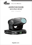
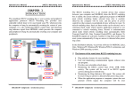
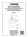
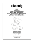
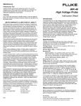
KQ30
Congratulations! You have just purchased the latest in equalization
technology to carry the famous KICKER name. Your KICKER KQ30 is
designed and built to give you years of trouble-free performance.
This installation manual contains valuable information on how to get
the most out of your new KQ30 equalizer. Thanks for buying KICKER.
Enjoy!
Features
30 Bands at 1/3 Octave Spacing Allows precise adjustment at each 1/3
octave measured frequency from 20 Hz to 20 KHz.
12 dB Boost or Cut Available at each of the 30 bands.
High Voltage Preamp Accepts 500 mV to 9 Volts audio signal and supplies up
to 9 Volts of output.
Separate Left and Right Input Controls Allows precise adjustment to
input sensitivity and channel balancing.
Separate Left and Right Output Controls Allows for full control of output voltage and channel balancing.
Separate Left and Right Input Clipping LED’s Visual indicators to aid in
setting input gain controls.
Separate Left and Right Output Clipping LED’s Visual indicators to aid in
setting output level controls.
Mono / Stereo Selector Allows one KQ30 to equalize both the left and right
channels or two units for independent left and right equalization settings.
EQ / Bypass Switch Allows you to defeat the equalizer and compare equalized and non-equalized sound.
Two Year Warranty When purchased from and installed by an Authorized
KICKER dealer.
Mounting Instructions
When selecting a location to mount your Kicker KQ30 equalizer be sure it is
structurally sound and that there are no items behind the area that could be
damaged by the screws. Check for wiring, brake lines, fuel lines, gas tanks, etc.
Remember that the controls on top of the equalizer will need to be accessible
for adjustment later. Keep this in mind as you choose your equalizer’s mounting
location.
Now that you are ready to mount your equalizer, use the KQ30 chassis as a
template and mark the four mounting hole locations with a marking pen. Use a
7/64” drill bit to pre-drill the four holes and then use the supplied screws to
securely mount the equalizer.
30
2
Wiring Instructions
When working with power connections it is always recommended that you disconnect the battery to prevent accidents. For ease of use, the power plug can
be removed from the KQ30 and then re-inserted after all wiring is completed.
The ground should be connected to the equalizer first before making any of
the other connections.This wire should be as short as possible (36 inches or less)
and connected to a paint/corrosion free solid metal area of the car’s chassis
using 18 Ga wire and a small ring terminal.
Connect the +12V terminal to a constant 12 volt battery source using 18 Ga
wire and an in-line 5 amp fuse.
The turn on terminal is connected to your source unit’s remote turn-on lead.
Most source units have an output labeled ‘power antenna’ or ‘amplifier turn-on’
for this connection. If your source unit has both, use the output labeled ‘amplifier turn-on’.
GROUND
TURN ON
+12V
30
GROUND
REMOTE TURN-ON
5A FUSE
+12V
BATTERY
3
Wiring Instructions (continued)
The use of twisted pair interconnects is recommended for all installations to
minimize noise. When routing these cables through the automobile, try to keep
them away from factory wiring harnesses and other power wiring. If you need to
cross any of this wiring do so at a 90 degree angle to reduce the possibility for
noise problems.
RCA Outputs
L
SOURCE UNIT
R
30
INPUT
L
R
OUTPUT
L
R
L
L
R
L
R
R
To Crossover or Amplifier
Mono operation.
For more details download our white paper on the KQ30 from www.kicker.com
INPUT
L
R
EQ
BYPASS
STEREO
OUTPUT
MONO
L
R
MONO mode
selected
To Source Unit
4
In MONO mode the
Left and Right
channel outputs
are the same. Use
either one or both
depending on your
application.
To Crossover or Amplifier
Adjusting Equalizer Controls
Once all the wiring connections have been made, the gain controls on your
KQ30 and amplifier(s) must be adjusted for optimum performance.
Gain Setting Procedure
1. Turn the gain controls on your amplifier(s) all the way down.
2. Disconnect the remote turn-on lead(s) from your amplifier(s). Be sure to insu-laate the exposed copper wire with electricaal taape to prevent accidentaal daamaage
to your source unit’’s remote turn--on leaad output..
Step 3
3. Set all the equalization controls on the KQ30 to their center
detent (0 dB) position.
4. Set the input gain controls at their minimum (fully counter
clock-wise) position.
5. Set the output level controls at their minimum (fully counter
clock-wise) position.
Step 4
6. Using a well recorded CD with a strong signal or a continuous
1KHz tone recorded at 0 dB (track 10 from AutoSound 2000 CD
104), turn your head unit up to 90% of it’s maximum output.
7. Turn the left channel input gain control up until the left
channel input clipping LED starts to flash.
Step 5
8. Adjust the right channel input gain control to match the left.
9. Turn the left channel output level control up until the left
channel output clipping LED starts to flash.
10. Adjust the right channel output level control to match the
left.
11. Turn the head unit down and shut off the system.
12. Re-connect the remote turn-on leads to your amplifier(s).
Step 7
The KQ30 will have enough output to operate most amplifiers
to their full power output even with the amplifier’s gain control
set at its lowest position. If necessary, the gain setting on your
amplifier(s) may be turned up slightly. Remember, the gain settings on any amplifier are for level matching only, they do not
increase the power output of your amplifier. The lowest gain
setting that will allow your amplifier to make full power is always
best for sound quality, lowest system noise and reliability.
If after making your adjustments to the equalization settings
the output clipping LED’s stay steadily lit, you will need to turn
down the output level controls and repeat steps 2, 6 and 9-12.
Step 8
Step 9
30
Step 10
Steps 7 & 8
Clipping LED's
Steps 9 & 10
Clipping LED's
5
Specifications
Operaating voltaage::
Chassis Fuse:
11 to 16 volts DC
2A mini-ATC
Audio Signa
al::
Minimum input voltage:
Maximum input voltage:
Maximum output voltage:
SNR (signal to noise), A Weighted:
Channel Separation:
500 mV RMS
9 Volts RMS
9 Volts RMS
Re: 9 Volts / 120 dB
Re: 9 Volts / 80 dB
Equa
alizaation::
30 bands
1/3 octave centering
+/- 12 dB per band
measured in Hz.
25, 31.5, 40, 50, 63, 80, 100, 126, 156,
200, 250, 320, 400, 500, 635, 800, 1K,
1.27K, 1.6K, 2K, 2.5K, 3.2K, 4K, 5K,
6.4K, 8K, 10K, 12.8K, 16K, 20K
Dimensions::
Width:
Depth:
Height:
10.25 in / 26.04 cm
7.50 in / 19.05 cm
1.125 in / 2.86 cm
My Settings
30
1.6 kHz
2 kHz
100 Hz
126 Hz
2.5 kHz 3.2 kHz
156 Hz
200 Hz
25 Hz
Min
L Max Min R
INPUT GAIN
5 kHz
6.4 kHz
8kHz
250 Hz
320 Hz
400 Hz
500 Hz
31.5 Hz
40 Hz
50 Hz
63 Hz
10 kHz 12.8 kHz 16 kHz
635 Hz
800 Hz
1 kHz
20 kHz
1.27 kHz
80 Hz
L Max Min R Max
OUTPUT LEVEL
Max
Min
INPUT
6
4 kHz
OUTPUT
ELECTRONICS LIMITED WARRANTY
Kicker warrants this product to be free from defects in material and workmanship under normal use
for a period of THREE (3) MONTHS from date of original purchase. When purchased from and installed
by an Authorized KICKER Dealer it is warranted for TWO (2) YEARS from date of original purchase, or
ONE (1) YEAR from date of original purchase if purchased from but not installed by an Authorized KICKER Dealer. If the product is labeled “B Stock” and purchased from an Authorized KICKER Dealer, it is warranted for ONE (1) YEAR from date of purchase, regardless of place of installation. Should service be necessary under this warranty for any reason due to manufacturing defect or malfunction during the warranty period, Kicker will replace or repair (at its discretion) the defective merchandise with equivalent
merchandise at no charge. Warranty replacements on “B-Stock” merchandise may have cosmetic scratches and blemishes. Discontinued products may be replaced with more current equivalent products.
This warranty is valid only for the original purchaser and is not extended to owners of the product
subsequent to the original purchaser. Any applicable implied warranties are limited in duration to a period
of the express warranty as provided herein beginning with the date of the original purchase at retail, and
no warranties, whether express or implied, shall apply to this product thereafter. Some states do not
allow limitations on implied warranties, therefore these exclusions may not apply to you.
This warranty gives you specific legal rights; however you may have other rights that vary from state to
state.
WHAT TO DO IF YOU NEED WARRANTY OR SERVICE
Defective merchandise must be returned to your local Authorized Stillwater Designs (Kicker) Dealer for
warranty. Assistance in locating an Authorized Dealer can be obtained by writing or calling Stillwater
Designs direct. You can confirm that a dealer is authorized by asking to see a current authorized dealer
window decal.
If it becomes necessary for you to return defective merchandise, call the Kicker Customer Service
Department at (405)624-8510 for a Return Authorization (RMA) number. Package all defective items in the
original container or in a package that will prevent shipping damage, and return to
Stillwater Designs, 5021 North Perkins Road, Stillwater, OK 74075
The RMA number must be clearly marked on the outside of the package. Return only defective components. Return of entire cabinets, system packs, pairs, etc. increases your return freight charges. Nondefective items received will be returned freight collect.
Include a dated proof-of-purchase stating the Customer name, Dealer name, product purchased
and date of purchase. Warranty expiration on items without proof-of-purchase will be determined from
type of sale and the manufacturing date code. Freight must be prepaid; items received freight collect will
be refused.
Failure to follow these steps may void your warranty. Any questions can be directed to the Kicker
Customer Service Department at (405)624-8510.
WHAT IS NOT COVERED?
•
•
•
•
•
•
This warranty is valid only if the product is used for the purpose for which it was designed.
It does not cover:
• Items previously repaired or modified by any
Damage due to improper installation
unauthorized repair facility
Subsequent damage to other components
• Return shipping on non-defective items
Damage caused by exposure to moisture,
• Products with tampered or missing barcode labels
excessive heat, chemical cleaners, and/or UV
• Products returned without a Return Authorization
radiation
(RMA) number
Damage through negligence, misuse, accident
• Freight Damage
or abuse. Repeated returns for the same
• The cost of shipping product to Kicker
damage may be considered abuse.
• Service performed by anyone other than Kicker
Any cost or expense related to the removal or
• Speaker with any foreign caulk used for gasket
reinstallation of product
material
Speakers damaged due to amplifier clipping or
distortion
HOW LONG WILL IT TAKE?
Kicker strives to maintain a goal of 24-hour service for all returns. Delays may be incurred
lif lack of replacement inventory or parts is encountered.
INTERNATIONAL WARRANTY
Contact your International Kicker dealer or distributor concerning specific
procedures for your country’s warranty policies.
P.O. Box 459 • Stillwater, Oklahoma 74076 • U.S.A. • 405 624-8510
WARNING:
KICKER drivers are capable of producing sound levels that can permanently
damage your hearing! Turning up a system to a level that has audible distortion is more damaging to your ears than listening to an undistorted system at
the same volume level. The threshold of pain is always an indicator that the
sound level is too loud and may permanently damage your hearing.
Please use common sense when controlling volume!
August 2002