1
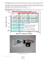
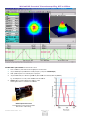
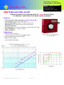
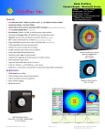
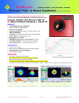
Beam m Profilin ng Cam mera Based –WinC CamD Series Range:: 190 nm m - 16 µm* Smallestt pixel: 3.2 x 3.2 µm* Smallestt Beam: 32 µm* ** Imaged A Areas*: 6.3 x 4 4.8 to 20 x 15 mm m * Sensor d dependent, **Direct m measurement, se ee p. 3 Feattures NEEW UV‐ Ultra‐ H High Resolution BladeCam™ witth UV option to 190 nm, 3.2 µm m pixel size, 3 M Mpixels, ½” form mat NEEW HyperCal™ D Dynamic Noise aand Baseline Corrrection software (Pat. Pending) NEEW CTE™ Comett Tail Elimination n for λ> 900 nm (Pat. Pending) NEEW Compact, Hiigh resolution 16 6‐bit ADC Camerra, 1600 x 1200 aarray, 1/1.8”, pixxels 4.4 µm USSB 2.0 port‐pow wered; flexible 3 m cable; no exteernal power sup pply required. USSB 3.0 compatib ble 0.65” (16.5 mm) U Ultra‐thin Blade eCam (includes N ND filter) to fit tight beam trainss [0.45”/11.5 mm m without filter] on‐chip 10‐bit orr external 14/16 6‐bit ADC Digital CCD/CMOSS cameras with o er & on‐board microprocessor 4 MB image buffe Window‐free senssors standard for no fringing W 255,000:1 electronic auto‐shutter, 40 s to 1000 m ms 1,0000:1 SNR (30/6 60 dB Optical/Ele ectrical) Pu ulsed laser auto‐‐trigger & synchrronization Iso olated Pulse Trigggering and Paraallel capture on m multiple cameraas Fieeld‐replaceable image sensors Laarge area TaperC CamD options to o 20 x 15 mm (p.77) X‐‐Ray, UV, 1310 n nm (p.8), 1475‐1680 nm (p.10) & 2‐16 µm Windows 7, Vista and XP, 32 and 64 bit. PC or Maac‐Intel using Parallels or BootCaamp W App plications CW W & Pulsed laser profiling Fieeld servicing of llasers and laser‐‐based systems Op ptical assembly & & instrument alignment Beeam wander & lo ogging M Measurementts 2 Cam‐HR/XHR sho own actual size BladeC 1.8 x 1..8 x 0.65” (0.45”” without filter) [46 x 46 x 16.5 mm] WinCaamD Series Camera shown actuaal size 2.40 xx 2.65 x 1.12” (x0 0.9” without filte er) [61 x 67 x 2 28 mm] www.laser2000.com GER/AT/CH Laser 2000 GmbH 82234 Wessling Tel. +49 8153 405-0 [email protected] www.laser2000.de New ‐ Mo ore Powerrful Beam Analysis SSoftware LLog profile displays, no averagin ng. Without HyperCal™ W With HyperCal™ 00.3% noise + basseline tilt Noise <0 0.1% & flat base eline nclusion Region Auto‐In n on an Elliptical Beam Automatically isolates the appropriatee analysis region. nd multi‐beam feeatures. With user overrides an With 1064 nm m Comet Tail With CTE™ ™ ™ Comet Tail Elim mination @ λ> 9 900 nm CTE™ Sttandard Linear P Profile with Gausssian Fit. Beam Wand der on a driftingg Laser The same profile with Av veraging & Log 40 dB d display reveals strructure in the wings s of the beam at lev vels below 1% WinCa amD Datasheet Ver. V 1201 Upp to 8192 samplles at a User Set interval. Mean, RMS and Maax. deviation. Reeplay Fast or Slow w. Export to Exccel, Paint, Bitmap p or Clipboard. Loggarithmic Profile e shows more de etail near baselin ne Page P 2 of 14 DataaRay Innovation ‐ The com mpany that brougght you the firstt Windows‐basedd CCD beam proofiler, the first Caamera for confin ned spaces, the first so oftware slider exxposure and ele ectronic auto‐shutter, the first sttandard window w‐free CCD for no fringing, the fiirst auto‐orientaation on the ellipsee & the first USB B 2.0 beam profilling camera … haas done it again. Compact WinCamD ca ameras: Fully featured cameras small enough to o fit in your shirtt pocket, or to fiit in a space 0.655” thick. Featurees: D Digital serial link for EMI immunity X XY profiles and ccentroids LLinear and logariithmic displays G Gaussian and Top Hat least squaares fits EEllipse Angle, Maajor, Minor, Meaan Diameters WinCaamD‐U CCD & CMOS Senso or Specifications: WinCamD™ ‐UCD12 NEW Backgrounnd capture and ssubtraction Image & Inntensity Zoom Linear andd area filters Image Aveeraging, 1 to conntinuous Compact ddesign 0.65” Proobe style for tigh ht applications ‐UCD15 NEW with UV Option to o 190nm High Resolution n ‐UC CD23 ‐HR*** ‐XHR**** ‐FIR2‐16 1110 kPixel Pixel Count & 1.4 M Pixel 1.9 MPixel, 1.4 M M Pixel 1.3 MPixel, 3.1 MPixeel, 3384 x 288 H x V: 1360 x1024 1600 x 1200 1360 0 x1024 1280 x 1024 2048 x 15336 7.1 x 5.4 6.6 x 5.3 Sensor image area (mm): 6.3 x 4.8 8.8 8 x 6.6 6.5 x 4.9 113.4 x 10.1 Pixel dimension (µm): 4.65 x 4.65 4.4 x 4.4 6.45 5 x 6.45 5.2 x 5.2 3.2 x 3.22 35 x 35 Min. beam (10 pixels): ~350 µm ~47 µm ~65 µm ~44 m ~52 m ~32 m Shutter type: Synchronous Synchronous Synch hronous Rolling Rolling Sam mpled Array Maxx. full frame rate: ~5‐10 Hz ~5‐10 Hz ~5‐‐10 Hz ~5‐10 Hz ~5‐10 Hzz TThermal ≈ 60 ms ~5‐10 Hz NA ~10 Hz Max. ‘every pulse’ PRR: ~5‐10 Hz ~5‐‐10 Hz NA Single pu ulse capture PRR: 20 kHz 20 kHz 20 0 kHz 20 kHz 20 kHz NA 1,000:1 1000:1 1000:1 >100:1 Sign nal to RMS Noise: 1,000:1 1,0 000:1 30/60* dB 30/60* dB 30/60* dB Opt./Elec.* dB: 30/60* dB >20/40* dB 30/6 60* dB EElectronic Shutter 44 dB 44 dB 44 4 dB 44 dB 44 dB 9 dB Dynamic Range: 112** dB; 113** dB; 113** dB Call ND+Shutter+SNR 113** dB; 113** dB; B; 11 11 11 11 11 1.6 :1 2.10.10 :1 Call 2.10 :1 2.1 Dynamic Range**: 10 :1 2.10.10 ::1 TaperCaamD‐UCD12 pixel 11 x 11 m NA NA NA NA NA size: NA TaperrCamD20‐15 pixel NA NA NA NA 15 x 15 m ADC: 14‐bit 16‐bit 14 4‐bit 10‐bit 10‐bit 14‐bit * OK K, we agree that qu uoting electrical dB for optical SNR iis nonsense, but so ome suppliers do tthis, so we offer aa comparable speccification. ** OK K, we agree that Dynamic Range that includes removaable ND filters is also nonsense, but some suppliers doo this, so we offer comparable speciification with ND *** Avvailable in both BlaadeCam™ and Win nCamD™ housings Commo on WinCamD/BladeCam Series SSpecifications: [Specifications are [ subject to changee without notice] Wavelen ngth: Standard ‐1310 ‐NIR ‐FIR ‐UV ~350 to 11 150 nm ~350 to 13 330 nm. Residual ssilicon response. 11290 nm long‐passs filter and light gu uard tube provided d. ~1480 to 1 1680 nm. NIR to V Visible conversion phosphor (Erbium m response), 40 m m FWHM Point Sprread Function ~2 to 16 aand 35 µm pixel pittch, 384 x 288 pixeels, 13.4 x 10.8 mm m ~190 to 11 150 nm UV converrters with wavelenngth options downn to X‐ray. UV reso olution to 1m. High dyynamic range to 1 113 dB electronic (see no otation under charrt**) 25,000:1 (44 dB) continuou usly variable auto eelectronic shutterr, <40 s to 1.0 s. A Additional 10,000::1 ND filter + 5:1 9 electronicc control to give 10 :1. Pulsed lasers Auto‐triggger sync, TTL input trigger, TTL outpput trigger Interfaace Port Powered USB 2.0 for laaptops & desktopss. 3 m standard thhin cable, 5 m option. USB 3.0 comp patible Multip ple Heads: 1 – 8 cam meras. Parallel captture, serial read. ISO 11146 Beam pro ofile Second mome ent processing Certificcation RoHS, WEEEE, CE Measu urable Sources CW beam ms, Pulsed sourcess. CW to 25 kHz w with single pulse isoolation, user confiigurable Synchron nous, Asynchronou us & Variable Delay trigger op ptions. Software e programmable trrigger input, +ve oor –ve edge, 2 k iimpedance Measured Beam Powers Manual Beam Attenuation: Optionss: WinCa amD Datasheet Ver. V 1201 See the SSaturation Beam P Power/Pulse Energgy Graph and Notees, below. Provided N ND 4.0 (10,000:1) C‐mount Neutral Density filters. [ND D 4.0 at 546 nm, h higher in blue, low wer in near IR.] Scre ew stackable ND 0.5, 1, 2, 3, 4, 5 available. EAM‐2: 4‐wheel stepped vaariable attenuatorr, 0 to 90 dB CUB and C CUB‐UV 3 to 10 % %, 30 arc minute w wedge samplers foor high power beam ms 1% and 0.05% Holographic B Beam Samplers (bby Gentec‐eo) Page P 3 of 14 Measurement Accuracy 0.1 m processing ressolution for interpo olated diameters. Absolute accuracy is beam profile d dependent – ~1 m m accuracy is frequently achievable. Centtroid accuracy is also beam depende ent. It can be as goood as ±1 m sincce it is arithmetically derived from all pixels abovve the centroid clip level. Measured & Displayed Profile Parametters Beam m Diameter: Diam meter at two user set Clip levels Gau ussian & Second M Moment beam diam meters Equ uivalent diameter aabove a user definned Clip level uivalent Slit and Kn nife Edge diamete rs Equ m Fit: Gau ussian & Top Hat p profile fit & % fit Beam Equ uivalent Slit profile e pticity: Majjor, Minor & Mean n diameters. Auto‐‐orientation of axees. Ellip Centtroid Position: Relative and absolute e Inte ensity Weighted Centroid and Geom metric Center Beaam Wander Display and Statistics oothing Filter: Triangular running filtter up to 10% FWH HM Smo Displayeed Profiles & Plotss X‐Y P Profiles, 2D, 3D Plo ots. Zoom to x10 10, 3 32, 16,384 or colors or gray scale. Co ontoured display aat 10 and 32 colorr. Processing Options HyperCal™ Real‐time electronic baseline correction ™ Comet Tail Elimination CTE™ Imagge & profile averaging, 1, 5, 10, 20, C Continuous Backkground Capture aand Subtraction Userr set Capture Block option *.job b files save all Win nCamD custom setttings for particulaar test configuratioons Pass/Faail display Log dataa and statistics On‐sscreen, in selectab ble Pass/Fail colorss. Ideal for QA & PProduction. Min., Max., Mean, Staandard Deviation. Up to 4096 sampl es Relativee Power Measurem ment Fluence Rolliing histogram base ed on user’s initial input. Units of m mW, µJ, dBm, % or user choice (relattive to a referencee measurement inp put) Flue ence, within user d defined area Chip dep pth from front of ccase /filter ring all ±~0.2 mm, ±0.5 mm m max WinCamD‐UCD12 WinCamD‐UCD15 WinCamD‐UHR/ XHR WinCamD‐UCD23 Blad deCam‐HR/ XHR Outline and Mounting W x H x D See Drawings Below WinCamD‐Series 2.65 x 2.4 x 0.9/1 1.13” Without/W With ND4 filter (667 x 61 x 23/29 mm m) deCam‐HR/ XHR 1.8 x 1.8 x 0.45/0 0.65” Without/W With ND4 filter (446 x 46 x 11.5/16.55 mm) Blad Camera Head Weight WinCamD 155 gm (5.5 5 oz); BladeCam‐ 4 42.5 grams (1.5 oz ) 8.4 / 13.4 mm (ccurrent, verify witth factory) 5.8/ 10.8 mm (ccurrent, verify withh factory) 8.7/ 13.7 mm (ccurrent, verify witth factory) 7.2 / 12.2 mm (ccurrent, verify witth factory) 5.0/ 10.0 mm (ccurrent, verify withh factory) Minimum Computer Requ uirements: 2 GH Hz processor or higgher running Wind dows 7/ Vista/XP, 32 or 64‐bit; 2 GB B RAM; 200 MB Haard Drive space; 1024 4 x 768 monitor, SStandard USB 2.0 h hi‐power (500 mA)) port or USB 3.0 pport. PC or Intel‐Mac Outlin ne and Mounting (not to scale) BladeCam‐H HR/XHR WinCa amD Datasheet Ver. V 1201 Page P 4 of 14 W WinCamD Satu uration Beam m Power/ Pu ulse Energy G Graphs Thesee two graphs allo ow you to simply determine the e approximate m maximum CW opptical power (abbove) or pulse eenergy (below) that the standard WinCaamD/BladeCam configuration can c measure forr your beam diaameter and wavvelength withouut additional attenuation. The Saturation Limiit assum mes: ‐ The provid ded ND 4.0 filter in place ‐ The electro onic shutter set at 40 s, its low west value ‐ The ADC gain set at 1, its lowest value ‐ The beam onto the ND filtter must not excceed 2.5 x (Beam m diam. in mm) W, or 10 W totaal power for largge beams. 400 nm 500 nm 1064 nm 675 nm 800 nm 400 nm 500 nm 1064 nm 675 nm 800 nm Rela ative Exposure vs. Wavelengtth 100 The lo ower limit in the standard configguration is ~10‐5 x the Saturation n Limit. 10 Use th he graph right to o estimate for otther wavelength hs. 1 3 300 50 0 700 Wavelength in nm WinCa amD Datasheet Ver. V 1201 Page P 5 of 14 900 1100 ORD DERING INFO ORMATION 33 Year Warrantyy Free e Software Upgrades 30 Dayy Sale or Return n Evaluation PO A Com mplete System co omprises: USB 2 2.0 Camera, ND 4 4.0 filter, Softwaare, 3 m (10 ft) CCable, User Manual. Generrate the Part Number based upo on the component descriptions, and limitations,, in the table. Your C CCD or CMOS ch hip choice does n not affect the system price, exce ept for the –UCD D15 & ‐UCD23 CC CD chips which ccost more. Part N Number = Camera a type + CCD/CMOS cchip + SSuffix (if requireed) BladeCaam ‐HR/‐XHR ‐‐UV/‐1310/‐NIR WinCam mD ‐UCD12/ ‐UCD15/ ‐UCD23/‐U UHR/‐XHR ‐‐UV/‐1310/‐NIR TaperCaamD ‐UCD12 ‐‐1310/‐NIR TaperCaamD20‐15 ‐UCD23 ‐‐1310/‐NIR e.g. W WinCamD‐UCD12 is a complete working system with a High Ressolution CCD sennsor with 4.65 m pixels. TTaperCamD‐1310 is a complete working system with a 14.4 x 10 0.8 mm FO Tapeer for 1310 nm. Part Number Descriptions WinCaamD‐UCD12 ½” CCD sen nsor for CW and pulsed, 1360 x 1 1024 pixels, 6.3 xx 4.8 mm, 4.65 xx 4.65 µm pixel WinCaamD‐UCD23 ⅔” CCD sen nsor for CW and pulsed, 1360 x 1 1024 pixels, 8.8 x 6.6 mm, 6.45 xx 6.45 µm pixel 1 /1.8” CCD sensor for CW an nd pulsed, 1600 x 1200 pixels, 7..1 x 5.4 mm, 4.44 x 4.4 µm pixel WinCaamD‐UCD15 BladeC Cam‐HR BladeC Cam‐XHR ½” CMOS se ensor for CW an nd high PRR, 128 80 x 1024 pixels, 6.6 x 5.3 mm, 55.2 x 5.2 µm pixeel also available in WinCCamD‐ WinCamD‐UHR NE EW ½” CMOS se ensor for CW an nd high PRR, 204 48 x 1536 pixels, 6.5 x 4.9 mm, 33.2 x 3.2 µm pixeel also available in WinCCamD‐ WinCamD‐XHR TaperCamD‐UCD12 WinCamD‐U UCD12 with 14.4 4 x 10.8 mm 2.25 5:1 FO taper on the sensor TaperCamD20‐15‐UCD D23 WinCamD‐U UCD23 with 20 xx 15 mm 2.27:1 FO taper on the sensor. ‐1310 Adds 50 mm m C‐mount tube e and long‐pass ffilter for 1290 too 1350 nm work.. ‐UV Camera witth 3 mm UG11 fiilter instead of N ND 4.0. Works att 260 through 3880 nm. ‐IR On‐chip IR tto visible phosphor converter fo or 1480 to 1600 nm. ‐FIR2‐16 Complete IR R camera for 2 tto 16 µm Extraa cameras are available at a red duced cost and come with Cable, Mount and ND D filter, but no Sooftware or User Manual. Confirm m with factory. Add additional suffix ‐X to the system Partt #. E.g.: WinCam mD‐UHR becom es WinCamD‐UHR‐X Acceessories 2 2 EAM‐22 Variable Atttenuator, 93 dB op ptical dynamic ran nge. Max.: 1 W/cm m ; 100 mJ/cm . CUB & CUB‐UV Vis & UV Be eam wedge splitte ers, 3% to 10% (po olarization dependdent) C‐mount to ccamera. ND0.5,, ND1.0, ND2.0, ND D3.0, Additional Neutral Density filters in ND 1 stepss in stackable C‐moount threaded holders. (ND4.0 filter comes as standaard with the system.). See User Manual fo ND4.0,, ND5.0 or curves. (Add L aafter ND for use w with TaperCamD200‐15, e.g. NDL3.0) M‐Sq quared Option for WinCamD – USB 2.0 M2DU‐WC 2 WinCamD‐SSeries USB 2.0 M Scan: 2.5 µm step ps, 44 mm travel addd lens below. ‐LNZ‐UV‐focal length 185 ‐ 450 nm Mounted fu used silica singlet llens. (22 mm aperrture) 185 to 450 nnm Standard Foca l lengths ‐ 50, 75, 100, 150, 250, 5000 mm ‐LNZ‐VIS‐focal length Mounted acchromat lens (22 m mm aperture) 400 0 ‐ 700 nm, Standaard Focal lengths ‐ 50, 75, 100, 150, 250, 500 mm (47 mm ape erture) 250, 500 m mm. 400 ‐ 700 nm ‐LN NZ‐NIR‐ focal lengtth 630 ‐ 1100 nm ‐LN NZ‐TEL ‐ focal length 1030 ‐ 1800 nm (47 mm ape erture) 250, 500 m mm. Mounted acchromat lens 650 to 1100 nm. (22 m mm aperture) Stanndard Focal lengthhs ‐ 50, 75, 100, 15 50, 250, 500, 750, 11000 mm (47 mm ape erture) 250, 500 m mm. Mounted TEL achromat lens. (22 mm aperture)) 1050 to 1620 nm m, Standard Focal llengths ‐ 50, 100, 150, 250, 500 mm m (47 mm ape erture) 250, 500 m mm. Otheer DataRay Profiiling Instrumentts 2, Beam mMap2 Real Time e M‐Squared Multti‐plane profiler 0.1 µm resolution oon CW lasers. Foccus, Alignment, Divergence, M Visiible and Telecom wavelengtths, Dual Detectorr 190 nm to 2.4 µm m. Beam m’R2 0.1 µm sampling on CW lase ers, 0.5 µm to 4 m mm beam dimensioons, Dual Detectorr 190 nm to 2.4 µm m. Beam mScope‐P8 100 µm to o 23 mm, M acce essory option, ISO 11146 Standard Linear scanning sllit, CW or Pulsed ((PRR >5 kHz) laserrs, up to 23 x 45 mm scann ned area, 190 nm tto 1.8 µm. 2 WinCa amD Datasheet Ver. V 1201 Page P 6 of 14 TapeerCamD for Direct Imaging of Larger Beams TaperrCamD‐UCD12 and a TaperCamD2 20‐15‐UCD23 se eries beam proffiling cameras arre unique to DaataRay and offer a larger effecttive imager area a. TaperCamD series cam meras offer dire ect imaging of th he beam withoutt any of the Gauussian beam neaar‐field/far‐field issues that arisee with the use o of beam expansion telesscopes. They aare available in sstandard, ‐1310 and –NIR versio ons. Fiber optic tapers are fused coherentt fiber bundles, h heated, drawn aand polished to ggive an output eend the size of the imager chip. The image is de e‐ magnified (M<1) from m the faceplate input to the imaager chip end. Th he taper ends a re bonded to thhe surface of thee imager chip ussing a proprietary DataR Ray process whicch eliminates both surface reflecctions and therm mal cycling stresss. The PMF (Pixel Multiply Facctor) shown below and on the ccamera label is entered into thee software in orrder to provide correct diamete er readings. NA at the im mager end is 1.0. NA at the inputt faceplate is a ffactor of M smal ler (0.45) light aat higher angles will be attenuated. The individu ual fibers at the input end are 6 µm pitch with a 50% core/claddding area ratio. Refractive in ndex is 1.81, leading to a front ssurface reflectivity of 8.3%. Residual disstortion is speciffied by the manu ufacturer at ±3% % barrel/pin‐cushhion distortion. In our experiencce this distortion n is concentrated towards the e edges of the fie eld. Residual no on‐uniformity in optical response is generally small and requ ires no correctiion, but the abiility to do so is available in the software. Empty filterr holders are avaailable for both TTaperCamD sizess. A 0.25” deep extension ringg is available with male and female 1.30”‐20 tpi threads. Ima ager area is sho own actu ual size in mm m for: 1.0"-32 C-m mount thread 6.5 ND4 4 at 3 o nCamD-UCD12 Win deCam-HR/ XH HR Blad 4.8 8 7.5 nCamD-FIR216, 2-16 µm Win 6 6.6 13.0 0 mm 8.04 25.7 7 mm 20.0 mm m nCamD-UCD23 Win nCam-UCD15 Win 6 6.86 5.4 7.1 14 D-UCD12, PM MF = 2.25 TaperCamD 10.5 12 TaperCamD-UCD1 2 20 TaperCamD20-15-UCD23 15 ND D4 at 3o 16.7 mm 34.4 mm 1.30" 20 tpi thread 28 8.0 mm 1.0 0"-32 C-mount thread TaperCamD D20-15-UCD2 23, PMF = 2.2 27 WinCa amD Datasheet Ver. V 1201 Page P 7 of 14 WinC CamD‐UCD1 12‐1310: Higgh Resolutio on beam pro ofiling to 13550 nm. Imagee of a 1310 nm b beam, 100 µm diameter, 1.5 mW W. [43 ms Shutte er, no ND filter] The hiigh resolution ad dvantage of 4.65 5 µm square pixe els is clearly seen. Summ mary: 1) TTechnology. Win nCamD‐XXXX‐13 310 uses proprie etary software and a electronics in conjunction with sensors th hat exhibit resid dual sensitivity at a 11310 nm. This is a tailing silicon response, and h has been observe ed out to at leasst 1340 nm. Thee effective Quanttum Efficiency (Q QE) in this tailing response is around 0.01%, i.e. a factor of around d ~104 down on the visible respoonse. 2) FFeatures. Despite the low QE, W WinCamD‐XXXX‐1 1310 cameras caan be very attracctive for 1310 nm m region use if the source irradiance is adequate (ssee later). The 4 4.65 micron squ uare pixels give much higher resolution than sttandard NIR cam meras. The WinC CamD shutter exxposure of up to 11047 ms is 25 to 30 times greate er than that of sttandard camerass, partially comppensating the low w 1310 nm senssitivity. 3) O Operational Issu ues. ND filters are not normallyy used with Win nCamD‐XXXX‐13 10, unless the bbeam power is very high, mean ning that norma al laaboratory backgground can dominate the 1310 n nm signal. Options are: ‐ Use no filter and work in a darkkened room, or w with black screening ‐ Use a long passs filter which blocks radiation be elow the wavelen ngth(s) of intereest. D DataRay supportts both options. No Filter Op peration. With no n shading or filtering, a typicaal room backgroound level is equuivalent to an eexposure time o of ~3 ms. i.e. the background is ~10% of the ssignal when the exposure time w with signal is ~00.3 ms. This empphasizes the neeed to suppress tthe ambient ligh ht ossible. Workingg in a darkened llab is the best so olution. as far as is po The provided d 50 mm long, 30 mm OD, blackk‐anodized C‐mo ount tube, reducces ambient lab bbackground by aa factor of aroun nd 4. A 100 mm lo ong tube will reduce the ambient lab background by a factor of aaround 8. With thin black card and taape, you can mo ount your own custom tube offf the provided 50 mm C‐moun nt extension, an nd customize the ambient suppression shading to your applicaation. WinCa amD Datasheet Ver. V 1201 Page P 8 of 14 Long‐Pass Fiilter Option. DaataRay provides the WinCamD‐XXXX‐1310 cam mera with an anggled, C‐mount W WCD‐LPF1290 ccustom long passs filter, with ≥8 80% transmissio on above 1295 nm, 50% transmission at 1290 nm m, 1% transmisssion at 1285 nm,, fully blocked beelow 1250 nm. This filter pro ovides very effective blocking of visible light, e..g. ambient lightt or laser pump signal. It has a ccustom construcction to minimize fringing effeccts, but can still lead to some frringing due to internal reflectionns in the filter saandwich and bettween the filter rear surface and the CCD. Filters with lower ccut‐on wavelengths can be obtaiined to special oorder. me. Use the grap ph below to estimate the requirred exposure tim me for your beam m. Exposure Tim Maximum Beam Power. No ote the red line iindicating to the e maximum pow wer of 100 mW allowed on the CCD. Above thiss level, you musst use samplingg or attenuation to reduce the b beam power. W WinCam D/1310 Sensitiv vity Lim mits 100 (85% of o ADC) Max Beam B Power = 100 mW 10 Beam Power in mW 1 1 * 100 1,000 Exposure in ms For example, e to give g an 85% saturation s levell on the ADC:: 0 0.1 At 13 310 nm, a 10 0 micron diam meter 2 mW beam will re quire a shutte er osure time of o ~ 30 ms. expo 0..01 At < 1310 nm, will be lowe r. At > 1310 nm, will be greatter. 10 0.0 001 10 100 1,000 0 Be eam 13.5 % Diametter in mic crons Com mplete WinCam mD‐XXX‐1310 sysstem includes: WinCamD D, WCD‐LPF1290 0 long pass filter,, CM‐50 50 mm tube, 3 m cable, Sofftware CD, User r manual. WinCa amD Datasheet Ver. V 1201 Page P 9 of 14 10,00 00 WinCam mD‐NIR: Economical Telecom beam m profiling, 11475 to 1600 0 nm WinCaamD‐NIR & Tape erCamD‐NIR forr Telecom C & L bands 1475 to 160 00 nm, IR to visible conversion p phosphor on Siliccon CCD ≈25 m FWHM point spread d function due tto phosphor ( ≈7 70 µm for CamIR R Adapter) ±10% spatiaal response non‐‐uniformity due to phosphor ~20 W to 1 100 mW, for 1 m mm diam. @1550 0 nm. (With 0.02 2% transmissionn (1550 nm) ND ffilter) e.g. 10 ms e exposure on 1 mW, 1 mm diame eter beam at 155 50 nm. Gamma: Siggnal = (Incident IIrradiance) whe ere γ =1.414. Gamma (γ) correction is inccluded in the sofftware. Ca amIR Adapter w with C‐mount 3.5:1 facceplate to senso or image reductio on 46 mm diam. x 9 4 97 mm long WinCa amD Datasheet Ver. V 1201 Page P 10 of 14 Prelim minary Datta Sheet Cameraa Based ‐ FFIR Profilin ng Range:: 2 - 16 µ µm Pixel Siz ze: 17 µm Smallestt Beam: 170 µm m Imaged A Areas: 10.9 x 8.2 mm NE EW Win nCamD-FIR2--16-HR R Co ompact, Po ortable, Port-Powered, USB 2.0 2-16 µ µm Beam Profiling for Windows 7, XP X & Vista a, 32 or 64 4 bit operating systtems Fea atures 17 7 µm pixel pitch, p 640 x 480 pixels,, WinCamD--FIR2-16-HR R 2 to 16 µm wavelength w range microbolometer Po ort Powered d USB 2.0; flexible f 3 m cable, no pow wer brick 14 4-bit ADC, 4 MB image buffer b & on-bo oard microprrocessor 10 0 ms time constant c No Chopper Measure M Pulsed or CW Bea ams, externa al trigger I/O on BNC R Room Tempe erature - no cooling requiired NETD = 0.05 K TBC App plications s MIR/FIR/CO2 laser profiling g based system ms Field servicing of CO2 lasers and laser-b Optical assemb bly & instrum ment alignmen nt eam wander & logging Be High Resolutio on IR Imaging g WinCa amD-FIR2-16-HR R Datasheet Ver. 1205a Page P 11 of 14 Powerful Beam Analysis Software Standard Linear Profile with Gaussian Fit Beam Wander on a drifting Laser Up to 8192 samples at a User Set interval. Mean, RMS and Max. deviation. Replay Fast or Slow Export to Excel, Paint, Bitmap or Clipboard Logarithmic Profile shows more detail near baseline WinCamD-FIR2-16-HR Datasheet Ver. 1205a Page 12 of 14 Features: Digital serial link for EMI immunity XY profiles and centroids Linear and logarithmic displays Gaussian and Top Hat least squares fits Ellipse Angle, Major, Minor, Mean Diameters Background capture and subtraction Image & Intensity Zoom Linear and area filters Image Averaging, 1 to continuous PC Or Mac-Intel Operation WinCamD-FIR2-16-HR Specifications: [Preliminary specifications- subject to change without notice] 2 to 16 µm Wavelength Ranges Compact 2.40” x 2.65” x 1.1” [61 x 67 x 27.9 mm] Interface USB 2.0 for laptops & desktops. 3 m standard thin cable, 5 m option. ISO 11146 Beam profile Second moment processing Certification RoHS, WEEE, CE Measurable Sources CW beams, Pulsed sources. Measured Beam Powers See the Saturation Beam Power/Pulse Energy Graph and Notes, below. Manual Beam Attenuation: Contact Application Engineer for options Measurement Accuracy 5 m processing resolution for interpolated diameters. Absolute accuracy is beam profile dependent – ~10 m accuracy is frequently achievable. Centroid accuracy is also beam dependent. It can be as good as ±10 m since it is arithmetically derived from all pixels above the centroid clip level. Pixel Count & H x V: 307 kPixel, 640 x 480 Sensor image area: 10.88 x 8.16 mm Pixel dimension: 17 x 17 µm Min. beam (10 pixels): 170 µm Shutter type: Max. full frame rate: Rolling 10 Hz Max. ‘every pulse’ PRR: 10 Hz TBC Single pulse capture PRR: TBD Signal to RMS Noise: (Opt./Elec.* dB): TBD ADC: 14-bit NETD: < 0.05 K Pulsed lasers Auto-trigger sync, Multiple Heads: 1 – 8 cameras. Parallel capture, serial read. Measured & Displayed Profile Parameters Beam Diameter: Diameter at two user set Clip levels Gaussian & Second Moment beam diameters Equivalent diameter above a user defined Clip level Equivalent Slit and Knife Edge diameters Beam Fit: Gaussian & Top Hat profile fit & % fit Equivalent Slit profile Ellipticity: Major, Minor & Mean diameters. Auto-orientation of axes. Centroid Position: Relative and absolute Intensity Weighted Centroid and Geometric Center Beam Wander Display and Statistics Smoothing Filter: Triangular running average up to 10% FWHM Displayed Profiles & Plots X-Y Profiles, 2D, 3D Plots. Zoom to x10 10, 16, 256 or max. colors or gray. Contoured display at 10 and 16 color. WinCamD-FIR2-16-HR Datasheet Ver. 1205a Page 13 of 14 Proce essing Options Image & profile p averagin ng, 1, 5, 10, 20 0, Continuous Backgroun nd Capture and d Subtraction *.job files s save all WinC CamD custom ssettings for parrticular test configurations Pass/ /Fail display Avera aging Log d data and statisttics On-screen n, in selectable Pass/Fail colo ors. Ideal for Q QA & Productio on. Beam dimension running g average up to o 50 samples Min., Max.., Mean, Standard Deviation. Up to 4096 sa amples Relative Power Measurement Fluence Rolling his stogram based on user’s initia al input. Units of mW, µJ, dBm, % or use er choice (relative to o a reference measurement m iinput) Fluence, within w user defiined area Came era Head Weigh ht 155 gm (5 5.5 oz); Minim mum Computerr Requirements s: 2 GHz processor running g Windows 7/V Vista/XP, 32 or 64-bit; 1 GB R RAM; 60 GB Ha ard Drive space; 102 24 x 768 monitor, USB 2.0 h hi-power (500 m mA) port. PC o or Intel- Mac Ord dering Informatio on 11 Year Warrantyy Free Software Upgraades 30 Day Sale or Return on qu ualified Evaluatiion POs A Complete Syste em comprises: USB 2.0 Came era, ND filter, S Software, 3 m (10 ft) Cable, User Manual. www.laser2000.com GER/AT/CH Laser 2000 GmbH 82234 Wessling Tel. +49 8153 405-0 [email protected] www.laser2000.de