1
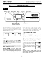
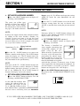
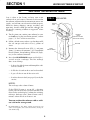
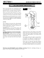
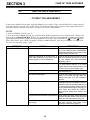
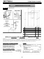
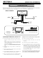
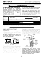
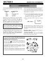
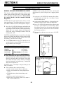
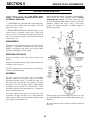
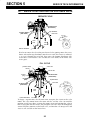
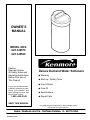
OWNER’S
MANUAL
MODEL NOS.
625.348570
625.348590
Caution:
Read and Follow
All Safety Rules and
Operating Instructions
Before First Use of
This Product.
Deluxe Demand Water Softeners
◆ Warranty
◆ Start Up / Setting Timer
◆ How It Works
If you have questions when
installing, operating or maintaining your softener, and
when setting the timer, call
this toll–free number...
1–800–426–9345
◆ Care Of
◆ Specifications
◆ Repair Parts
SAVE THIS MANUAL
Use plastic bag and tie provided, to hang manuals nearby
the softener for future reference.
PRINTED IN U.S.A.
WARRANTY
SEARS RESIDENTIAL WATER SOFTENER
FULL ONE YEAR WARRANTY ON WATER SOFTENER
For one year from the date of purchase, when this water softener is installed and maintained
in accordance with our instructions, Sears will repair, free of charge, defects in material or workmanship in this water softener.
FULL TEN YEAR WARRANTY AGAINST LEAKS
For ten years from the date of purchase, Sears will furnish and install a new current model water
softener tank or salt storage drum, free of charge, if either the tank or drum develop a leak.
TO OBTAIN WARRANTY SERVICE, SIMPLY CONTACT THE NEAREST SEARS SERVICE
CENTER THROUGHOUT THE UNITED STATES. This warranty applies only while this product
is in use in the United States.
This warranty gives you specific legal rights, and you may have other rights which vary from
state to state.
Sears, Roebuck and Co., D/817 WA, Hoffman Estates, IL 60179
&" $! &" $! ! & ! ! ! &" $ ! "!& !! & "!' ! SEARS INSTALLATION POLICY
!! & ! $ $! & ! ! ! "! !! & $! $ "! " !
!! " !! &
" ! ! !& ! " !&
SEARS INSTALLATION WARRANTY
! ! & $!& %! ! &" !
## $ $!& (
!# ! ! ! !
" ! $ & !! # "!& $! & $
" ! &" " " "! ! ! ! ! ! ! &"
FACTS AND FIGURES TO KEEP
Fill in the blanks below and keep this book in a safe
place so you always have these facts.
Water Softener Model No.†
Serial Number
Date Installed
Water Hardness
Grains Per Gallon
Iron Content
Parts Per Million
*pH
Taste And/Or Odor
Water Pressure
Pounds/Square Inch
Water Flow Rate
Gallons Per Minute
† The model number is on the rating decal, located on
the rim, under the salt hole cover.
2
TABLE OF CONTENTS
PAGE
NO.
SECTION 1
A.
B.
C.
D.
E.
SAFETY GUIDES
CHECK LIST OF STEP-BY-STEP GUIDES TO INSTALL
PROGRAM THE TIMER
SANITIZING THE WATER SOFTENER
FILL THE STORAGE TANK WITH SALT
SECTION 2
A.
B.
A.
15
16
17
18
OTHER THINGS TO KNOW
DIMENSIONS/SPECIFICATIONS
SECTION 5
10–11
12-14
CARE OF YOUR SOFTENER
SALT: REFILLING STORAGE TANK, SALT BRIDGE
KEEPING THE WATER SOFTENER CLEAN
KEEP THE SOFTENER FROM FREEZING
HELPFUL HINTS CHECKLIST
SECTION 4
4
5
6-7
8
9
HOW YOUR WATER SOFTENER WORKS
FACE PLATE TIMER FEATURES
SOFT WATER SERVICE AND REGENERATION
SECTION 3
A.
B.
C.
D.
SOFTENER START UP
19
SERVICE TECH INFORMATION
A. TROUBLESHOOTING
B. ROTARY VALVE SERVICE
C. WATER FLOW THROUGH THE SOFTENER VALVE
20-23
24
25-27
SECTION 6
28-31
REPAIR PARTS
3
SECTION 1
1A.
WATER SOFTENER START-UP
SAFETY GUIDES
▲ Read all steps, guides and rules carefully before installing and using your new water softener.
Follow all steps exactly to correctly install. Failure to follow them could cause personal injury or
property damage. Reading this book will also
help you to get all of the benefits from your water
softener.
▲ Your water softener will remove hardness minerals and “clear water” iron from water, up to the
limits shown on page 19. It will not remove other
types of iron, acids, tastes and odors, etc. It will
not purify polluted water or make it safe to drink.
▲ Protect the softener and piping from freezing.
Damage from freezing voids the softener warranty. See page 17.
CAUTIONS
PLEASE READ AND COMPLY WITH THE FOLLOWING GUIDES TO PREVENT DAMAGE TO
THE SOFTENER OR OTHER PROPERTY,
PERSONAL INJURY, OR POSSIBLE FATAL
SHOCK.
▲ THIS SOFTENER WORKS ON 24 VOLTS
ONLY. BE SURE TO USE THE TRANSFORMER
INCLUDED, AND PLUG IT INTO A 120V OUTLET.
▲ Unplug the transformer right away if the
power cable sould become damaged or
frayed. Make repairs before plugging back
into the power outlet.
▲ Always unplug the softener from electrical
power before removing outer valve covers.
4
SECTION 1
1B.
WATER SOFTENER START-UP
CHECK LIST OF ALL STEP-BY-STEP GUIDES TO INSTALL
Refer to the Installation Manual, part no. 7159931, for
stepĆbyĆstep guides.
To be sure you have done all the steps to install the
softener, read the following list. Page numbers
referred to are in the ✔ Is the house water flow going INTO the softener
valve INLET? Trace piping to be sure. See pages
10 and 11.
✔ Is the plumbing bypass valve (or 3 valves) set for
SERVICE? See FIG. 12, page 19 of this manual.
✔ Is the valve drain hose connected the right way,
and without sharp bends or kinks that could stop
or reduce water flow? See page 16.
✔ Is the softener power cable connected to the
transformer? Is the transformer plugged into 120VĆ60Hz electrical outlet? See page 20.
3–valve
brass
✔ Be sure to restart the water heater. See page 20.
plastic
5
SECTION 1
WATER SOFTENER START-UP
1C.
PROGRAM THE TIMER
FIG. 1
signal light adjust
salt level adjust
SALT
LEVEL
ADJUST
display
SALT
LEVEL
UP button
SIGNAL
LEVEL
SIGNAL
LIGHT
ADJUST
Kenmore Water Line
for Customer Assistance
1–800–426–9345
LOW
SALT
SELECT button
SELECT
ON/OFF
HOLD
RECHARGE TONIGHT
RECHARGE NOW
Deluxe Demand Water Softener
with Dual Segment Electronic Display
ON/OFF–HOLD button
(Recharge Tonight–Now)
DOWN button
When the transformer is plugged in, the model code
SR31, and a test number (example: k10) show in the
face plate display for 4 seconds. Then, 12:00 AM and
PRESENT TIME begin to flash.
button. For example, while setting the hardness
(step 2), the beeper sounds repeatedly when the
display reaches 1 using the DOWN button, or the
highest hardness setting using the UP button.
1. SET PRESENT TIME OF DAY:
AM
NOTE:
PRESENT TIME
If the words PRESENT TIME do not show in the
display, press the SELECT button (FIG. 1) until they
do, or see the previous notes.
■ Press the UP / DOWN buttons to set the present
time. Press UP to move the display ahead; press
DOWN to move the time backward.
NOTES:
If SR- - shows in the display, press the UP
or
DOWN button until SR31 shows. Then, press the
SELECT button to set, and change to the flashing
PRESENT TIME display.
If the present time is between
noon and midnight, be sure PM
shows.
To check the model code, unplug the transformer at
the wall outlet and plug in again. if other than SR31
shows, see page 18 to reset.
If the present time is between
midnight and noon, be sure AM
shows.
SOUND BEEPER": A beeper" sounds while
pressing buttons for timer setĆup. One beep signals a
change in the face plate display. Repeated beeps
mean the timer will not accept a change from the
button you have pressed, telling you to use another
PM
PRESENT TIME
AM
PRESENT TIME
NOTE:
Each press of the UP /DOWN buttons changes the
time by 1 minute. Holding the buttons in changes the
time 32 minutes each second.
6
SECTION 1
1C.
WATER SOFTENER START-UP
PROGRAM THE TIMER
2. SET WATER HARDNESS NUMBER:
■ Press the SELECT button once to display 25
(flashing) and HARDNESS.
Bypass, page 14). If a different recharge time setting
would be better for your household, do the
following.
The grains per gallon (gpg)
hardness of your water supply is
on your water analysis report.
Be sure to enter water test results
on page 2, for future reference.
■ Press the UP / DOWN buttons to set the desired
recharge starting hour. Be sure to observe the
AMĆPM as you did when setting the present time of
day.
HARDNESS
NOTE:
Each press of the UP / DOWN buttons changes the
display 1 hour. Holding the buttons in changes the
display twice each second.
NOTE:
If your water supply contains iron, compensate for it
by adding to the water hardness number. For
example, assume your water is 20 gpg hard and
contains 2 ppm iron. Add 5 to the hardness number
for each 1 ppm of iron. In this example, you would
use 30 for your hardness number.
2 ppm iron x 5 = 10
(times)
4. SET CLEAN FEATURE (optional):
■ Press the SELECT button to display OFF
(flashing) and CLEAN.
This feature is beneficial on
water supplies containing iron
CLEAN
and/or high amounts of sediĆ
ments (sand, silt, dirt, etc.).
When set to ON, a backwash and
fast rinse cycle will occur first,
CLEAN
preceeding the normal regenĆ
eration sequence (see page 12).
This provides extra cleaning of
the resin bed before it is regenerĆ
ated with the salt brine. To conserve water, if your
water supply does not contain iron or sediments, be
sure this feature is set to OFF. Use the UP / Down
buttons to change the ON / OFF displays.
20 gpg hardness
+10
30 HARDNESS NUMBER
■ Press the UP / DOWN buttons to set your water
hardness number in the display. The DOWN button
moves the display to 1. The UP button moves the
display to the highest setting (see maximum setting
for your model in the specifications).
NOTE:
Each press of the UP / DOWN button changes the
display by 1 between 1 and 25. Between 25 and the
highest number, the display changes 5 at a time…25,
30, 35, etc. Holding the UP or DOWN button in
changes the display twice each second.
■ Press the SELECT button once again, to return
the present time, and RECHARGE TONIGHT in the
display.
3. SET RECHARGE (REGENERATION) TIME:
■ Press the SELECT button to display 2:00 AM
(flashing) and RECHARGE TIME.
8 OFF
7
6
5
4
AM
At the 2:00 AM recharge time
RECHARGE
setting, the softener begins reĆ
TIME
generation (see pages 12 and
13) at 2:00 AM, ending no later
than 4:00 AM. This is a good time in most households
because water is not being used (see Automatic
Serv
PM
RECHARGE TONIGHT
3
2
1
WATER FLOW
IF YOU NEED HELP PROGRAMMING THE TIMER, CALL TOLL FREE, NUMBER 1-800-426-9345.
SEE PAGES 10 AND 11 FOR OTHER FACE PLATE TIMER FEATURES.
7
SECTION 1
1D.
WATER SOFTENER START-UP
SANITIZING THE WATER SOFTENER
Care is taken at the factory to keep your water
softener clean and sanitary. Materials used to make
the softener will not infect or contaminate your water
supply, and will not cause bacteria to form or grow.
However, during shipping, storage, installing and
operating, bacteria could get into the softener. For
this reason, sanitizing as follows is suggested① when
installing.
FIG. 2
Salt Hole
Cover
hose
1. The first time you sanitize your softener, be sure
to do steps in the installation manual, and on
pages 5, 6 and 7 of this manual first.
2. Lift the salt hole cover and use a pail or hose to fill
the salt storage tank with at least 3 gallons of
water.
Brinewell
Cover
(remove and add
about 3/4 oz. bleach)
Brinewell
3. Remove the brinewell cover (FIG. 3) and pour
about 3/4 ounce of common 5.25% household
bleach (Clorox, Linco, BoPeep, White Sail, Eagle,
etc.) in the softener brinewell.
Water,
About 3 Gallons
4. Press the ON/OFFĆHOLD button and hold for 3
seconds to start a recharge. This first recharge
does several things.
Ċ It draws the bleach into and through the softĆ
ener to sanitize it.
Ċ It fills the salt tank to the water level needed.
Ċ It gets all the air out of the resin tank.
Ċ It makes the resin bed (see page 11) ready for
service.
NOTES:
This recharge takes about 2 hours.
If the CLEAN feature is set to ON, a cleaning
backwash will occur first (CLEAN and Bkwsh or
Rinse flashes in the display), before the sanitizing
recharge. Recharge takes about 2 hours and 15
minutes when the clean feature is on.
You can sanitize the softener salt in the storage tank.
①
ADD WATER
Recommended by the Water Quality Association. On
some water supplies, the water softener may need periĆ
odic disinfecting.
8
SECTION 1
1E.
WATER SOFTENER START-UP
FILL THE STORAGE TANK WITH SALT
Brine (salt dissolved in water) is needed for each and
every regeneration. The water for making brine is
metered into the salt storage tank by the softener.
However, you must keep the tank filled with salt.
FIG. 3 ADD SALT
Fill the tank with NUGGET or PELLET water softener
salt. DO NOT use rock salts, as they have dirt and
sediments that will stop the softener from working.
Before filling, be sure the brinewell cover is in place
on the top of the brinewell. Salt storage capacity is
shown on page 19. Be sure to set the salt monitor
system (see page 10).
NOTES:
The salt monitor system (page 10) is calibrated to the
density of nugget or pellet water softener salt. The
monitor will not work as accurately with other types
of salt including rock and solar.
In humid areas, it is best to fill the storage tank
halfĆfull, and to refill it more often. Salt bridging (see
page 15) occurs more often when conditions are
humid.
: Water softeners using sodium
chloride for regeneration add sodium to the water.
Persons who are on sodium restricted diets should
consider the added sodium as part of their overall
sodium intake.
WATER SOFTENING SALT WITH IRON REMOVING ADDITIVES — Some salts have an additive to
help the softener handle iron in the water supply.
Although this additive may help to keep the softener
resin clean, it may also release corrosive fumes that
will weaken and shorten the life of some softener
parts.
For example, if your water supply is 15 grains hard,
you would have to drink 3 quarts of softened water
to consume 335 milligrams of sodium. That is
equivalent to eating 2Ć1/2 slices of white bread.
Persons who are concerned about their drinking
water should consider a Kenmore Drinking Water
System that will remove or reduce in excess of 90% of
the sodium and other drinking water contaminants.
You have now finished the water softener start up. After the sanitizing recharge, on
page 8, the softener will be giving you soft water.
9
SECTION 2
2B.
HOW YOUR WATER SOFTENER WORKS
FACE PLATE TIMER FEATURES
EXTRA RECHARGE
Sometimes, a manually started regeneration (reĆ
charge) may be desired, or needed. Two examples
are:
--You have used more water than usual (guests
visiting) and you may run out of soft water before the
next timer started regeneration.
--You did not refill the softener with salt before it
was gone.
SALT MONITOR SYSTEM
The face plate timer has a low salt monitor with an
indicator light to remind you to refill the storage tank
with salt. To set this monitor system:
1. Lift the salt hole cover and level the salt in the
storage tank.
2. The salt level decal, on the brinewell inside the
tank, has numbers from 0 to 8 (see drawing on
page 9 and below). Observe the number the
leveled salt is at or closest to.
You can start a regeneration right away, or you can
set the timer to regenerate at the next 2:00 AM (or
other preset recharge time). Do the following.
3. Now, press the SALT LEVEL ADJUST button until
black bars display up to the salt level number. For
example, the pictures below show the salt level
at 6.
RECHARGE NOW
■ Press the ON/OFFĆHOLD
button and hold until *REĆ
RECHARGE
CHARGE, Serv and Fill begin to
flash in the display. Upon
reaching fill, the first cycle of reĆ
generation, the flashing Serv
goes off and Fill is on steady. RECHARGE continĆ
ues to flash. This regeneration will last for about 2
hours. After the 2 hours, you will have soft water
again.
*NOTE:
If the CLEAN feature is set to ON, a cleaning
backwash (CLEAN and Bkwsh or Rinse flashes in the
display, along with the minutes of the clean cycle
remaining) precedes the recharge.
8 OFF
7
6
5
4
Serv
Fill
4. Finally, set the level you want the low salt
PM
indicator light to come on. Press the SIGNAL
LIGHT ADJUST button until a (✴) shows
opposite this number. In the example below, the
light will come one when the stored salt drops to
level 2. At level 2, the storage tank is about 1/3
full. This is the lowest you should allow the
stored salt level to drop to. To turn the salt
monitor off, press the button until OFF shows.
3
2
1
WATER FLOW
NOTE:
For accurate salt monitor operation, always use
nugget or pellet water softener salt. See page 9.
SALT
LEVEL
RECHARGE TONIGHT
bars, salt
level
■ Press and release (do not
hold) the ON / OFFĆHOLD butĆ
RECHARGE TONIGHT
ton. RECHARGE TONIGHT
flashes in the display, and the
softener begins regeneration at
the next preset recharge time.
Press and release the ON/OFFĆHOLD button once
more if you decide to cancel the regeneration, and
RECHARGE TONIGHT.
8 OFF
7
6
5
4
PM
SALT
LEVEL
3
2
1
brinewell
decal
WATER FLOW
salt
level
SALT
LEVEL
ADJUST
SIGNAL
LIGHT
ADJUST
LOW
SALT
indicator light
10
SIGNAL
LEVEL
8
7
6
5
4
3
2
1
ON/OFF
HOLD
SECTION 2
2A.
HOW YOUR WATER SOFTENER WORKS
FACE PLATE TIMER FEATURES
WATER FLOW THROUGH THE SOFTENER
If soft water is in use, the water
flow bars continually scroll
across the display. The bars
scroll slowly when water flow is
no water flow
slow, and move faster as water
flow increases. The flow bars do
not show when all faucets and
water using appliances are off.
OPTIONAL SETTINGS– CLEAN FEATURE
MINUTES, MAXIMUM DAYS BETWEEN REGENERATIONS, and 12 / 24 HOUR TIME READINGS:
1. To set 1, 2 or all 3 options, press and hold SELECT
for 3 seconds. Then press again until the CLEAN
TIME display shows.
MIN
CLEAN
default minutes
WATER FLOW
8 OFF
7
6
5
4
WATER FLOW
Flow bars scroll when
soft water is in use.
example: time set to 3minutes
RECHARGE TIME REMAINING and VALVE
POSITION INDICATORS
recharge
One of the valve position indicaĆ valve
position
time
tors (Serv, Fill, Brine, Bkwsh, indicators remaining
Rinse) is displayed while the
softener is recharging (See
*NOTE on page 10 if the CLEAN
feature is ON). RECHARGE
flashes in the display and, beginĆ
ning with Brine, the minutes of recharge remaining
before return to service appears in place of the
present time. When the valve is moving from one
cycle to another, both position indicators are
flashing.
8 OFF
7
6
5
4
2. Press SELECT again to show the following
RECHARGE display.
DAY
default display
PM
3
2
1
TIME
CLEAN feature minutes: If you are using this
feature (page 7), the length of the extra backwash
cycle automatically sets to 7 minutes. However, you
can adjust this time from 1 to 15 minutes in length. To
change this cycle time, use the UP button to increase
the time, or the DOWN button to shorten the time. If
no change is desired, continue below.
RECHARGE
PM
3
2
1
MIN
CLEAN
TIME
8 OFF
7
6
5
4
3
2
1
DAY
RECHARGE
example: set to 4 days maximum between regenerations
Maximum days between regenerations: The
faceplate timer automatically controls regeneration
frequency (see page 14). This provides the greatest
operating efficiency, and normally the maximum
days feature is not needed. If you want to be certain
a regeneration will occur within a number of days,
use this feature. For example, if your water supply
contains iron and you want the softener to
regenerate at least once every few days to keep the
resin bed clean, set the display as typically shown
above. Setting is available from 1 to 15 days by using
the UP and DOWN buttons.
Serv
Fill
Brine
Bkwsh
Rinse
MIN
RECHARGE
TIME REMAINING
PROGRAM MEMORY
If electrical power to the softener goes off, the time
display is blank but the face plate timer keeps the
correct time for about 6 hours. When electrical
power comes on again, you have to reset the present
time only if the display is flashing. The HARDNESS
and RECHARGE TIME never require resetting unless
a change is desired.
Even if the timer is incorrect after a long power
outage, the softener works as it should to keep your
water soft. However, regenerations may occur at the
wrong time of day until you reset the timer to the
correct time of day.
3. Press SELECT to show the 12 HOUR display.
12 or 24 hour clock: All
time displays are shown in
TIME
standard clock time (1 to 12 PM;
and 1 to 12 AM) at the 12 hr
default setting. If military time
displays are desired, set to 24 hr
TIME
by pressing the UP button.
AM
PM
ERROR CODE
An error code could appear in
the face plate display if a probĆ
lem occurs in the softener elecĆ
tronics. If you see an error code
instead of the present time of
day, please call you local Sears
Service Department for service.
4. Press SELECT to return the present time display.
11
SECTION 2
2B.
HOW YOUR WATER SOFTENER WORKS
SOFT WATER SERVICE AND REGENERATION
SERVICE
When the softener is giving you soft water, it is called
Service". During service, hard water flows through
the house main water pipe into the softener. Inside
the softener resin tank is a bed made up of thousands
of tiny, plastic resin beads (FIG. 4). As hard water
passes through the bed, each bead attracts and holds
the hardness minerals. This is called ionĆexchanging.
It is much like a magnet attracting and holding
metals. Water without the hardness minerals (soft
water) flows out of the softener and into the house
soft water pipes.
REGENERATION
FILL: Salt, dissolved in water, is called brine.
Brine is needed to clean the hardness minerals from
the resin beads. To make the brine, water flows into
the salt storage area during the fill stage as shown in
FIG. 5. Fill cycle length depends on how much soft
water making capacity you have used since the last
regeneration. As you use more water, fill time
increases so more brine is made. The greater amount
of brine cleans more hardness minerals from the
resin bed.
FIG. 5 WATER FLOW THROUGH THE
After a period of time, the resin beads become
coated with hardness minerals and they have to be
cleaned. This cleaning is called regeneration or
recharge. Regeneration is started at 2:00 a.m. by the
electronic timer (see page 14). It takes place in 5
stages or cycles. These are:
1
2
3
FILL
BRINING
BRINE RINSE
4
5
SOFTENER IN FILL
soft water
OUT
BACKWASH
FAST RINSE
salt storage
tank
NOTE:
If the CLEAN feature (page 7) is set to ON, additional
backwash and fast rinse cycles occur before the fill
cycle.
brine valve
FIG. 4 WATER FLOW THROUGH THE
SOFTENER IN SERVICE
soft water
OUT
hard water
IN
ÎÎÎÎ
ÎÎÎÎ
ÎÎÎÎ
ÎÎÎÎ
ÎÎÎÎ
ÌÌÌÌÌÌÌÌ
ÎÎÎÎ
ÌÌÌÌÌÌÌÌ
ÎÎÎÎ
ÌÌÌÌÌÌÌÌ
ÎÎÎÎ
ÌÌÌÌÌÌÌÌ
ÎÎÎÎ
fill water
salt storage
tank (salt
not shown)
brine valve
hard water
IN
ÎÎÎ
ÎÎÎ
ÎÎÎ
ÎÎÎ
ÎÎÎ
ÎÎÎ
ÎÎÎ
ÌÌÌÌÌÌÌÌ
ÎÎÎ
ÌÌÌÌÌÌÌÌ
ÎÎÎ
resin tank
resin bed
12
SECTION 2
2B.
HOW YOUR WATER SOFTENER WORKS
SOFT WATER SERVICE AND REGENERATION
BRINING: During brining, the brine is moved
from the salt storage area, into the resin tank. Inside
the resin tank, brine cleans hardness minerals from
the resin beads and they are discharged out the
drain. How much brine is needed to clean the resin
depends on:
FIG. 7 WATER FLOW THROUGH THE
SOFTENER IN BACKWASH
hard water
bypass OUT
drain
ÎÎÎ
ÎÎÎ
ÎÎÎ
ÎÎÎ
ÎÎÎ
ÎÎÎ
ÌÌÌÌÌÌ
ÎÎÎ
ÌÌÌÌÌÌ
ÎÎÎ
ÌÌÌÌÌÌ
ÎÎÎ
--the amount of resin in the softener,
--how fast the brine goes through the bed.
The nozzle and venturi (FIG. 6) make suction to take
brine from the salt tank and put it into the resin tank.
They keep the brine flow down to a very slow rate to
get the best resin cleaning with the least salt.
BRINE RINSE: After all of the brine goes into the
resin tank, the brine valve closes. Water keeps
flowing the same way it did during brining except
the brine flow has stopped. Hardness minerals and
brine flush from the resin tank to the drain. Brining
and brine rinse together vary in the length of time
they take, relative to the fill cycle length.
resin bed lifted
and expanded
FAST RINSE: Backwash is followed by a fast flow
of water down through the resin tank. The fast flow
packs the resin bed and gets it ready for return to
service (FIG. 8).
FIG. 6 WATER FLOW THROUGH THE
SOFTENER IN BRINING AND
BRINE RINSE
hard water
bypass OUT
nozzle &
venturi
hard water
IN
After fast rinse, the softener returns to service. Hard
water goes into the resin tank where the resin bed
again takes out the hardness minerals. Soft water
goes to the house soft water pipes.
hard water
IN
FIG. 8 WATER FLOW THROUGH THE
drain
SOFTENER IN FAST RINSE
ÎÎÎ
ÎÎÎ
ÎÎÎ
ÎÎÎ
Î
ÎÎÎ
ÌÌÌÌÌÌÌ
Î
ÎÎÎ
ÌÌÌÌÌÌÌ
ÎÎÎ
soft water
OUT
hard water
IN
drain
brine valve
ÎÎÎ
ÎÎÎ
ÎÎÎ
ÎÎÎ
ÎÎÎ
ÎÎÎ
ÌÌÌÌÌÌ
ÎÎÎ
ÌÌÌÌÌÌ
ÎÎÎ
brine
BACKWASH: During backwash, water flows UP
through the resin tank (FIG. 7) at a fast rate to flush
iron minerals, dirt and sediments from the bed and to
the drain. The bed lifts and expands for good
cleaning.
13
SECTION 2
2B.
HOW YOUR WATER SOFTENER WORKS
SOFT WATER SERVICE AND REGENERATION
AUTOMATIC BYPASS
During the brining, brine rinse and backwash cycles
of regeneration, water goes through the
softener valve and to the house pipes. If a faucet is
opened, hard water is there for your needs.
However, you should not use water, if possible,
because the water heater will refill with hard water.
The softener regenerates from 2:00 AM to about 4:00
AM, (you can set anytime), a time when not much
water is used.
ELECTRONICS
Two main parts of the softener's electronics are a
WATER METER, and a COMPUTER.
WATER METER Ċ The water meter is in the
softener valve outlet. As water flows through the
meter, it sends electric pulses to the computer. The
computer changes the pulses to a measure in gallons
of water.
COMPUTER Ċ The computer is part of the circuit
board. It is programmed to know the softener's
capacity (how many grains of hardness minerals it
will take out of the water before a regeneration is
needed). When starting the softener, page 7, you set
it for the grains per gallon (gpg) hardness of the
water.
If you get up early in the morning and you can hear
the softener regenerating, change the time setting.
Set the recharge time to 12:00 AM or 1:00 AM (page
7). Then regeneration will start and end that much
earlier and your water heater will not refill with hard
water if a hot faucet is opened.
To find a regeneration pattern best for your needs,
the computer uses: (1) water usage from the meter,
(2) hardness setting, (3) softener capacity, and (4)
time since the last regeneration. The computer
always adjusts this pattern to your water using habits.
It works toward providing you with soft water for the
longest time and the most efficient salt usage.
Softening capacity is used as hard water goes
through the softener and hardness minerals are
removed, capacity is used. When the computer
determines that only enough capacity remains to
provide soft water up to the next regeneration
starting time (2:00 AM, or as otherwise set) it will
schedule a regeneration. RECHARGE TONIGHT
displays until the regeneration begins. When the
regeneration begins, TONIGHT goes off and *REĆ
CHARGE or RECHARGE TIME REMAINING flashes
during the 2 hour regeneration.
*NOTE:
If the CLEAN feature is set to ON, a cleaning
backwash (CLEAN and Bkwsh or Rinse flashes in the
display, along with the minutes of the clean cycle
remaining), precedes the recharge.
14
SECTION 3
3A.
CARE OF YOUR SOFTENER
SALT…REFILLING STORAGE TANK/BREAKING A SALT BRIDGE
all the salt before refilling. Without salt, you will soon
have hard water.
WHEN TO REFILL WITH SALT
The Salt Monitor System (see page 10) will turn on
the low salt light to warn you when to refill with salt.
Check for a low salt light a few weeks after you install
the softener, and every week after that. Always
refill at about the #2 salt monitor level. At this level,
the tank is about 1/3 full. Never let the softener use
NOTE:
You will have a loss in softening capacity and may
get partly hard water if less than 10 inches (salt
monitor level 2) of salt is in the storage tank.
PLEASE SEE PAGE 9 FOR SALT FILLING DIRECTIONS.
BE SURE TO RESET THE SALT MONITOR, PAGE 10.
SALT BRIDGE
FIG. 9 SALT BRIDGE
Sometimes, a hard crust or salt bridge forms in the
salt storage tank. It is usually caused by high
humidity or the wrong kind of salt. When the salt
bridges, an empty space forms between the water
and salt. Then salt will not dissolve (melt) in the
water to make brine. Without brine, the resin bed
does not regenerate and you will have hard water.
push tool into salt
bridge to break
1” – 2”
Pencil
Mark
If the storage tank is full of salt, it is hard to tell if you
have a salt bridge. Salt is loose on top, but the bridge
is under it. The following is the best way to check for
a salt bridge.
Broom Handle
Salt should be loose all the way to the bottom of the
tank. Hold a broom handle, or like tool, up to the
softener as shown in FIG. 9. Make a pencil mark on
the handle, 1″ or 2″ below the top height of the rim.
Then, carefully push it straight down into the salt. If a
hard object is felt before the pencil mark gets to the
top of the tank, it's most likely a salt bridge. Carefully
push into the bridge in a few places to break it. Do
not try to break the salt bridge by pounding on
the outside of the salt tank. You may damage it.
Salt
Salt Bridge
Water Level
If the wrong kind of salt made the bridge, take it out.
Then fill the tank with nugget or pellet salt only.
15
SECTION 3
3B.
CARE OF YOUR SOFTENER
KEEPING THE WATER SOFTENER CLEAN
COVERS
To keep your new Kenmore water softener looking
nice, apply a coat of paste wax and repeat once a
year. When dusty, wipe it with a damp cloth to keep
it sparkling.
NOTE:
Never use cleaners having ammonia or abrasives.
They may scratch and dull the surface.
NOZZLE & VENTURI
A clean nozzle and venturi (FIG. 10) is a must for the
softener to work right. This small unit moves brine
from the salt storage tank to the resin tank during
regeneration. If it becomes plugged with sand, silt,
dirt, etc., the softener will not work and you will get
hard water.
FIG. 10 CLEANING THE NOZZLE &
VENTURI
Cap
O–ring Seal
To get to the nozzle and venturi, remove the softener
top cover. Be sure the softener is in service cycle (no
water pressure at nozzle and venturi), then turn off
the cap from the nozzle and venturi housing. Do not
lose the large oĆring seal. Lift out the screen support
and screen, then the nozzle and venturi. Wash and
rinse the parts in warm water until clean. If needed,
use a small brush to remove iron or dirt. Also check
and clean the gasket flow plugs and screens.
Screen Support
Screen
*Flow Plug
(DUDC or DDUC)
Nozzle & Venturi
Gasket
Screen
IMPORTANT: Be sure small
holes in the gasket are centered directly over the small
holes in the nozzle & venturi
housing.
Carefully replace all parts in the correct order.
Lubricate the oĆring seal with silicone grease or
Vaseline and place in position. Install and tighten
the cap, by hand only. Do not overtighten and
break the cap or housing.
*Flow Plug
(HVDC)
Nozzle & Venturi
Housing
*Install with numbered side up concave
side down. Be sure the largest flow plug is
located in the nozzle & venturi housing.
maximum of clear water iron, an iron filter or other
equipment is needed. Your local Sears store has
trained people to help you with iron water problems.
IRON FROM THE RESIN BED
Your water softener takes hardness minerals (calĆ
cium and magnesium) out of the water. Also, it can
control some clear water" iron. See maximum
allowed in the specifications on page 19. With clear
water iron, water from a faucet is clear when first put
into a glass. After 15 to 30 minutes, the water begins
to cloud or turn rust colored. A water softener WILL
NOT remove any iron which makes the water cloudy
or rusty as it comes from the faucet (called red water
iron). To take red water iron out of water, or over the
If your water supply has clear water iron, even
though less than the maximum allowed, regular
resin bed cleaning is needed. Sears has resin bed
cleaner, Item No. 42Ć34426 for this. Clean the bed at
least every 6 months. If iron shows up in the soft
water before 6 months, clean more often. Printed
instructions are on the resin bed cleaner bottle.
16
SECTION 3
3C.
CARE OF YOUR SOFTENER
KEEP THE SOFTENER FROM FREEZING
If the softener is installed where it could freeze
(summer cabin, lake home, etc.), you must drain all
water from it to stop possible freeze damage. To
drain the softener Ċ
FIG. 11 DRAIN WATER FROM THE
SOFTENER
1. Close the shutĆoff valve on the house main water
pipe, near the water meter or pressure tank.
2. Open a faucet in the soft water pipes to vent
pressure in the softener.
3. Refer to FIG. 12 on page 19. Move the stem in a
single bypass valve to bypass. Close the inlet and
outlet valve in a 3Ćvalve bypass system, and open
the bypass valve. If you want water in the house
pipes again, reopen the shutĆoff valve on the
main water pipe.
7. Looking at FIG. 11, lay a piece of 2 inch thick
board near the floor drain. Move the softener
close to the drain. SLOWLY and CAREFULLY tip
it over until the rim rests on the wood block with
the inlet and outlet over the drain. Do not allow
the softener's weight to rest on the inlet and
outlet fittings or they will break.
4. Unplug the transformer at the wall outlet.
Remove the salt hole cover and the main cover.
Take off both drain hoses.
5. Carefully remove the large holding clips at the
softener inlet and outlet (see Key No. 61, on page
30). Separate the softener from the adaptors or
bypass valve.
8. Tip the bottom of the softener up a few inches
and hold until all water has drained. Leave the
softener laying like this until you are ready to use
it. Plug the inlet and outlet with rags to keep dirt,
bugs, etc. out.
6. Remove the brinewell cover and disconnect the
brine valve tubing at the nozzle and venturi
assembly (see page 30). Lift the brine valve out of
the brinewell. Tip the brine valve upside down to
drain out water.
17
SECTION 3
3D.
CARE OF YOUR SOFTENER
HELPFUL HINTS CHECKLIST
... TO HELP YOU SAVE MONEY
If your water softener fails to work, make the following easy checks. Often, you will find what's wrong yourself
and you won't have to call and wait for service. If you do not find anything wrong, while making the checks,
and your softener still does not work, call your Sears Service Department.
NOTES:
1. Also read ERROR CODE, page 11.
2. If an error code is not dispIayed, press and hold the SELECT button for several seconds until a flashing SR
code appears. It must show SR31. If SR 17, 22, 39 or 60 shows, the face plate computer is working on incorrect
input and would probably be the cause of the problem. To set SR31, press either the UP or DOWN button.
When SR31 shows, press SELECT to return a flashing 12:00 AM display. Reset the present time, hardness numĆ
ber and recharge time, pages 6 and 7.
PROBLEM
NO SOFT WATER
CAUSE
No salt (or salt bridged) in the storage tank
Transfomer unplugged at the wall outlet, or
power cable leads loose, fuse blown, circuit
breaker popped, or circuit switched off.
Manual bypass valve(s) in bypass position
Dirty, plugged or damaged nozzle & venturi
Valve drain hose plugged
WATER HARD SOMETIMES
Hardness number setting too low
Using hot water when softener is regenerating
Increase in the grains of hardness in your
water supply
18
CORRECTION
Refill with salt, or break the salt bridge (page
15). Press ON/OFF-HOLD (RECHARGE
NOW) button and hold for 3 seconds to start
a regeneration (see page 10).
Check for loss of power due to any of these
and correct. With the power back on, look at
the time display and read PROGRAM
MEMORY, page 11.
Look at FIG. 12 on page 19. Move the stem
in a single valve to service. In a 3-valve
bypass, open the inlet and outlet valves, and
be sure to fully close the bypass valve.
Take apart and clean or replace damaged
parts (see page 16).
The drain hose must not have kinks, sharp
bends, or be raised too high above the
softener (see page 16 in your installation
manual).
Press and release the SELECT button until
HARDNESS shows in the display. Read the
hardness number in the display and be sure
the same grains per gallon number is shown
on your water analysis report. See page 7 to
reset. Press and release the SELECT
button until the present time shows in the
display.
Avoid using hot water during this time
because the water heater refills with hard
water (see Automatic Bypass, page 14).
Ask your Sears retail or catalog store for a
new water analysis. Then make a new
hardness number setting (page 7).
SECTION 4
4A.
OTHER THINGS TO KNOW
DIMENSIONS/SPECIFICATIONS
FIG. 12 BYPASS VALVES
A
B
C
D
E
F1
F2
—
Salt Tank Height
Resin Tank Diameter (nominal)
Resin Tank Height (nominal)
Inlet-Outlet Height
Overall Height
Length
Width
Distance between inlet-outlet
center lines
MODEL NO. 625.348570 AND 625.348590
INCHES
CM
40-1/4
9
40
41-1/2
46
19-1/2
16-1/2
3-3/8
102.2
22.7
101.6
105.4
116.8
49.5
41.9
8.6
TIMER SR CODE SR31
NOTE: ! " ! #
" " #
WATER SUPPLY TO WATER SOFTENER
MINIMUM WATER SYSTEM FLOW (gpm)
MINIMUM-MAXIMUM WATER PRESSURE (psi)
MAXIMUM WATER TEMPERATURE (°F)
MAXIMUM WATER HARDNESS (gpg)
MAXMUM “CLEAR WATER” IRON (ppm)
OTHERS
3
20-120
120
110
7
TYPE OF ION EXCHANGE MATERIAL (resin) High Capacity
AMOUNT OF RESIN (cu.ft.)
1.0
REGENERATION (RECHARGE) CYCLE TIME (min.)
FILL
2.7-10.3
BRINING/BRINE RINSE
97-106
BACKWASH
7
FAST RINSE
3
TOTAL REGENERATION TIME ➀
109.7-126.3
SALT FOR WATER SOFTENER
TYPE OF SALT NEEDED
ALTERNATE TYPE OF SALT
Nugget/Pellet
Pure, evaporated, compacted
water softener salt
STORAGE CAPACITY (pounds)
200
gpm = gallons per minute
psi = pounds per square inch
gpg = grains per gallon
ppm = parts per million
➀ Does not include CLEAN feature cycle times if set to ON.
19
SECTION 5
SERVICE TECH. INFORMATION
5A.
TROUBLESHOOTING
Keep this manual with your water softener. If repairs are needed, the service technician must have the informaĆ
tion on the following 8 pages. For telephone assistance, call toll free, 1-800-426-9345.
WIRING SCHEMATIC
BACK OF TIMER
(PWA)
AC INPUT
POS / TURBINE
MOTOR
Motor, 24VAC
24VAC
Transformer
grn
Turbine
Sensor
NC Position
OUT
GND
+5
SALT
LEVEL
ADJUST
brn
NO
SALT
LEVEL
SIGNAL
LEVEL
SIGNAL
LIGHT
ADJUST
Sears Water Line
for Customer Assistance
1–800–426–9345
LOW
SALT
Switch
Deluxe Demand Water Softener
SELECT
ON/OFF
HOLD
RECHARGE TONIGHT
RECHARGE NOW
with Dual Segment Electronic Display
ALWAYS MAKE THESE INITIAL CHECKS FIRST
REMOVE THE TOP COVER AND SALT TANK COVER
1. Does the time display show the correct time of day?
6. Is there salt in the storage tank?
--If display is blank, check power source to the softĆ
ener.
--If time is flashing, power was off for over 24 hours. The
softener resumes normal operation but regenerations
occur at the wrong time.
--If an error code (Example: Err3) shows in the face plate
display, go to ELECTRONIC DIAGNOSĆ
TICS.
2. Plumbing bypass valve(s) must be in Full Service
position.
7. Is the brine tubing connected? (See water flow
diagrams).
8. Is the brine valve float set right? (See page 23).
9. Press the SELECT button 2 times to display the hardness
setting. Be sure it is the correct setting for the
household's water supply. (Make a hardness test of the
raw water and compare with the hardness setting. Also
test a soft water sample to verify if a problem exists.)
Press the SELECT button twice more to return to
present time in the display.
3. The inlet and outlet pipes must connect to the softener
inlet and outlet respectively.
If you do not find the problem after making initial checks,
do the INITIATED ELECTRONIC DIAGNOSTICS,
and the MANUAL ADVANCE REGENERATION CHECK.
4. Is the transformer plugged into a live", grounded wall
outlet, and the power cable fastened securely?
5. The valve drain hose must be free of kinks and sharp
bends, and not elevated over 8 ft. above the floor.
20
SECTION 5
SERVICE TECH INFORMATION
5A.
TROUBLESHOOTING
The chart below shows the error codes that could
appear, and the possible defects for each code.
AUTOMATIC ELECTRONIC DIAGNOSTICS
The face plate computer has a selfĆdiagnostic
function for the electrical system (except input
power and water meter). The computer monitors the
electronic components and cirĆ
cuits for correct operation. If a
malfunction occurs, an error
code appears in the face plate
display.
While an error code appears in the display, all face
plate buttons are inoperable except the SELECT
button. SELECT remains operational so the service
person can make the MANUAL INITIATED ELECĆ
TRONIC DIAGNOSTICS (below) to further isolate
the defect, and check the water meter.
POSSIBLE DEFECT
MOST LIKELY
CODE
Err1
Err2
Err3
Err4
Err5
LESS LIKELY
motor inoperative / wiring harness or connection to switch / position switch / face plate
face plate
See face plate replacement on
motor / face plate
page 22.
face plate / position switch
face plate
PROCEDURE FOR REMOVING ERROR CODE FROM FACE PLATE: 1. Unplug transformer 2. Correct defect
3. Plug in transformer 4. Wait for 6 minutes. The error code will return if the defect was not corrected.
If you don't get a reading in the display, with facuet
open, pull the sensor from the valve outlet port. Pass
a small magnet back and forth in front of the sensor.
You should get a reading in the display. If you get a
reading, unhook the in and out plumbing and check
the turbine for binding.
MANUAL INITIATED ELECTRONICS
DIAGNOSTICS
To enter diagnostics, press the SELECT button
and hold for 3 seconds.
You will see the following display, showing valve
cycle position, position switch status (open or
closed), and turbine operation.
valve position indicator
8 OFF
7
6
5
4
Serv
turbine count (water flowing)
8 OFF
7
6
5
4
3
2
1
WATER FLOW
Serv
3
2
1
WATER FLOW
position switch
indicator (open)
turbine count (no
water flowing)
TURBINE OPERATION: If no water is flowing through
the softener, the turbine indicator displays 3 zeros.
When water is flowing, the flow bar scrolls across the
display, and a 000 to 199 count repeats for each
gallon of water passing through the turbine. To
check for positive operation of the turbine if zeros
are shown, open a nearby water faucet and
observe the turbine count and flow bar.
POSITION SWITCH STATUS: WIth the valve in
service, or any of the recharge cycles, the switch
. While the valve is
indicator will show open
rotating from 1 position to another, the indicator will
. A defect is probable if
show the switch closed
indications vary from this pattern.
21
SECTION 5
5A.
SERVICE TECH. INFORMATION
TROUBLESHOOTING
…Press the UP button to display the number of days
this face plate has had electrical power applied.
…Press the DOWN button to display the number of
regenerations initiated by this face plate since the SR
code number was entered.
VALVE POSITION INDICATORS: Depending on the
valve position, the following indicators show in the
display:
INDICATOR
VALVE POSITION
Serv . . . . . . . . . service
Fill . . . . . . . . . . . fill
Brine . . . . . . . . . brining/brine rinse
Bkwsh . . . . . . . . backwash
Rinse . . . . . . . . fast rinse
2. Press the ON/OFFĆHOLD button to advance the
valve to each position and observe the switch
and position indicators to verify component
operation, or to possibly isolate a defect.
When the valve is rotating from 1 cycle to another,
both indicators flash. For example, if the valve is in
transition between fill and brining, both Fill and
Brine flash. Upon reaching brining position, Fill
goes off and Brine is on steady. The time display
shows the minutes of the cycle remaining.
3. Press and hold the SELECT button for 3 seconds
until…
...SR31 shows.
NOTE: If the face plate is left in a diagnostic display
(or a flashing display when setting times or
hardness), present time automatically returns if a
button is not pressed within 4 minutes. To return
to the diagnositc display, repeat step 2.
This code identifies the softener nominal capacity
size. If the wrong number shows, the softener will
operate on incorrect programming. Do the following
as needed.
SR31 does show Ċ Press the SELECT button to
return the present time display.
OTHER INFORMATION: While in this diagnostic screen,
the following information is available and may be
beneficial for various reasons. This information is
retained by the computer from the first time electrical
power is applied to the face plate.
To change SR number Ċ Press the UP or DOWN
button until SR31 shows. Then, press the SELECT
button and reset the timer…page 6.
FACE PLATE REPLACEMENT: BE SURE THE VALVE IS IN
SERVICE POSITION (OBSERVE VALVE CYCLE INDICATOR)
WHEN REPLACING THE FACE PLATE.
If, after installing and programming the replacement face
place, the valve is not in service position, do the following
to assure correct cycle orientation, or timing, between the
face plate and valve.
Use the MANUAL ADVANCE procedures, page 23. With the
RECHARGE NOW button, advance through the recharge
cycles until the valve stops in service position, and REĆ
CHARGE no longer flashes in the timer.
NOTE: The valve motor may automatically drive through
several valve positions while searching for service. If an erĆ
ror code occurs, unplug the transformer, then plug in again.
MOTOR
position
markers
CAM
22
SECTION 5
5A.
SERVICE TECH INFORMATION
TROUBLESHOOTING
NOTE: If water system pressure is low, an elevated
drain hose may cause back pressure, stopping brine
draw.
MANUAL ADVANCE REGENERATION CHECK
This check verifies proper operation of the valve
motor, brine tank fill, brine draw, regeneration flow
rates, and other controller functions. Always make
the initial checks, and the manual initiated
diagnostics.
3. Again press ON/OFFĆHOLD to move the softenĆ
er into backwash. Look for a fast flow of water
from the drain hose.
NOTES: The face plate display must show a steady
time (not flashing). If an Error code shows, first press
the SELECT button to enter the diagnostic display.
a. An obstructed flow indicates a plugged top disĆ
1. Press the ON/OFFĆHOLD button and hold in for
fast rinse. Again look for a fast drain flow. Allow
the softener to rinse for a few minutes to flush out
any brine that may remain in the resin tank from
the brining cycle test.
tributor, backwash flow plug, or drain hose.
4. Press ON/OFFĆHOLD to move the softener into
3 seconds. *RECHARGE and Fill begin to flash as
the softener enters the fill cycle of regeneration.
When Fill is on steady, remove the brinewell
cover and, using a flashlight, observe fill water
entering the tank.
*NOTE: If the CLEAN feature is set to ON, a cleaning
backwash (CLEAN and Bkwsh or Rinse flashes in the
display, along with the minutes of the clean cycle
remaining), precedes the recharge.
5. To return the softener to service, press ON/OFFĆ
HOLD.
a. If water does not enter the tank, look for an obĆ
structed nozzle, venturi, fill flow plug, brine tubĆ
ing, or brine valve riser pipe.
CYCLE FLOW RATES (GALLONS PER MIN.)
FILL (flow to salt storage tank)
0.3 (1.1 liters)
BRINING
.19 (.7 liters)
BRINE RINSE
.12 (.45 liters)
(flow to drain) 2.0 (7.6 liters)
BACKWASH
FAST RINSE
2.0 (7.6 liters)
2. After observing fill, press the ON/OFFĆHOLD
button to move the softener into brining. A slow
flow of water to the drain will begin. Verify brine
draw from the brine tank by shining a flashlight
into the brinewell and observing a noticeable
drop in the liquid level.
NOTE: Be sure a salt bridge is not preventing water
with salt contact.
a. If the softener does not draw brine…
…nozzle and/or venturi dirty or defective.
…nozzle and venturi not seated properly on
gasket.
…restricted drain (check drain fitting and
hose).
…defective nozzle and venturi seal.
…other inner valve defect (rotor seal, rotor &
disc, wave washer, etc.).
23
SECTION 5
5B.
SERVICE TECH. INFORMATION
ROTARY VALVE SERVICE
Before working on the valve, turn off the water
supply and disconnect from electrical power.
TO RELIEVE PRESSURE:
Lower the cover onto the valve body and rotor shaft.
Then install the cover holding screws. Before
tightening the screws, install the valve cam and
gear. Then, turn the rotor (clockwise only) to service
position. Tighten the screws using a crissĆcross
pattern. If a torque wrench is available, torque to
30Ć40 inch pounds.
--3 VALVE BYPASS: Close the inlet valve and open a
soft water faucet. Then close the outlet valve and
open the bypass valve.
--SEARS SPECIAL BYPASS: Slide the bypass valve
stem to bypass position. the 3 hex head
screws (see A in drawing) toward the back side of
the valve to allow pressure water to bleed out Catch
water with a rag.
DISASSEMBLY
To remove a part or group of parts, refer to the valve
drawing. A common screwdriver or nut driver,
Phillips screwdriver and pliers are the only tools
needed to completely disassemble.
SERVICING THE VALVE
Inspect all oĆrings, seals and gaskets for wear or
defects.
Inspect the bottom surface of the rotor and disc for
scratches, chips or wear.
NOTE: If replacement is needed, be sure to use the
current replacement part.
ASSEMBLY
Be sure all parts are in place and in the proper
position. Lubricate ALL oĆrings and seals with FDA
approved silicone grease. To install the rotor seal,
first place the seal into the valve groove, rounded
side down (see crossĆsection). Apply a light coating
of silicone grease to the seal's crossing ribs. Then,
carefully center the wear strip on the seal, and push it
downward onto the seal.
Install the nozzle and venturi seal and drain seal.
Assemble 2 oĆrings and the wave washer onto the
rotor and disc. Then center the rotor and disc, in the
valve body, on the rotor seal.
Lubricate the gear on the motor, and the valve cam
gear with Molykote grease, or other high quality gear
lubricant.
Be sure to orient switch as shown, with lever toward
the cam.
24
SECTION 5
SERVICE TECH INFORMATION
5C .. WATER FLOW THROUGH THE SOFTENER VALVE
SERVICE CYCLE
from Valve Inlet
(hard water)
top distributor
To Valve Outlet
(soft water)
resin tank
resin
bed
resin
bed
bottom distributor
FILL CYCLE
position switch
venturi
valve cam
rotor & disc
fill flow
plug
from Valve Inlet
(hard water)
fill water
(soft)
top distributor
resin tank
To Valve Outlet
(soft water)
resin
bed
resin
bed
bottom distributor
! 25
SECTION 5
SERVICE TECH. INFORMATION
5C. WATER FLOW THROUGH THE SOFTENER VALVE
BRINING AND BRINE RINSE CYCLES
bypass hard water
to valve outlet
venturi
drain
nozzle
from Valve Inlet
(hard water)
brine from
salt storage tank
After fill, timer/switch action allows the motor to turn the rotor and disc into
BRINING position. Water flow is directed to the nozzle. Suction, created by the
nozzle and venturi, draws brine from the salt storage tank and injects it into the resin
bed via the bottom distributor. Flow continues out the top distributor and to the
drain. Hard water is available at the valve outlet.
When the brine valve closes to end brine draw, water flow continues in the same
directions to slowly RINSE brine from the resin bed and to the drain.
BACKWASH CYCLE
bypass hard water
to valve outlet
flow plug
drain
Timer/switch action again allows the motor to turn the
rotor & disc to place the valve in BACKWASH, stopping
water flow to the nozzle. Water is routed down and out
the bottom distributor, up through the bed, and out the
top distributor to the drain. The fast flow (controlled by
a flow plug in the drain fitting) flushes dirt, sediments,
iron deposits, remaining brine and hardness to the
drain.
26
SECTION 5
SERVICE TECH INFORMATION
5C. WATER FLOW THROUGH THE SOFTENER VALVE
FAST RINSE CYCLE
soft water
to valve outlet
drain
" " # $ !! !! " ! !! ! # 27
SECTION 6
REPAIR PARTS
KENMORE WATER SOFTENERS
MODEL NOS. 625.348570 AND 625.348590
3
28
1
2
PART
DESCRIPTION
KEY
NO. NUMBER
1
7137604 Cover (main)
2
7137612 Salt Hole Cover
3
7095373 Transformer, 24V-10VA FY
4
7132840 Power Cord (transformer)
5
7183451 Timer Repl. (PWA)
6
7178464 Face Plate (order req’d decal)
7178749 Face Plate Decal, Mod 625.348570
7178757 Face Plate Decal, Mod 625.348590
7
7137599 Rim
8
7137727 Brinewell Cover
9
7082150 Wing Nut, 1/4″
10
7100819 Brinewell
11
7144619 Salt Storage Tank
12
7148875 Plastic Screw, 1/4″ x 5/8″
13
0900431 Hose Clamp FY
14
1103200 Hose Adaptor FY
15
9003500 Grommet FY
16
7116488 Brine Valve Assy. (also see pg. 29)
17
7105047 Replacement Distributor
18
0502272 Resin
19
7144952 Resin Tank (incl. Key No. 18)
20
7170270 O-Ring, 2-3/4″ x 3″
21
7077870 Top Distributor
22
7170254 O-Ring, 13/16″ x 1-1/16″
23
7170296 O-Ring, 2–7/8″ x 3-1/4″
24
7141001 Vapor Barrier
25
7176292 Clamp Section (2 req.)
26
7088033 Clamp Retainer (2 req.)
27
7137913 Decal, Salt Level①
28
–––
Cov. Lock (req’d. for shipment only)
7159931
Installation Manual
◆
Valve Assembly
(see page 30)
5
4
26
6
7
Rating Decal
Location
25
24
23
22
21
20
19
8
18
9
17
10
27
11
15
14
16
13
◆
7178731
Owners Manual
12
◆ not illustrated
FY Included in parts bags…see page 31.
① Aligns with top of brinwell.
28
SECTION 6
REPAIR PARTS
KENMORE WATER SOFTENERS
MODEL NOS. 625.348570 AND 625.348590
48
BRINE VALVE
ASSEMBLY
KEY
PART
DESCRIPTION
NO. NUMBER
30
7168647 Float Weight, Ceramic
31
0513860 Float Stop
32
7097202 Float (includes key no. 33)
33
0516947 Float Seal
34
7093216 Float Rod & Stem
35
7092278 Guide Cap
36
7170288 O-Ring 15/16 x 1-3/16
37
0516211 Seal
38
0516924 Retainer, Bottom Seal
39
7116713 Clip
40
7092252 Brine Valve Body
41
7080653 Clip
42
7131365 Screen
43
7094979 Insert
44
7092294 Retaining Ring
45
7092286 O-Ring, 5/16 x 9/16
46
7095470 Brine Tube
47
7113016 Tubing Assy. (incl Key Nos. 43, 44 & 45)
48
7171349 Cone Screen
49
7112997 Ground Clamp Kit FY
FY Included in parts bags…see page 31.
47
30
31
46
32
33
34
35
36
37
38
45
44
43
42
ÂÂ
41
INLET – OUTLET
GROUNDING CLAMPS
39
40
49
29
SECTION 6
REPAIR PARTS
KENMORE WATER SOFTENERS
MODEL NOS. 625.348570 AND 625.348590
95
50
94
51
93
52
53
92
VALVE ASSEMBLY
54
55
56
57
91
58
90
89
59
60
61
88
87
83
82
86
81
85
62
63
80
64
84
65
79
78
77
67
66
68
71
69
70
96
76
75
99
74
73
72
1
30
98
97
SECTION 6
REPAIR PARTS
KENMORE WATER SOFTENERS
MODEL NOS. 625.348570 AND 625.348590
PARTS LIST
KEY
PART
DESCRIPTION
NO. NUMBER
50
7131755 Screw, #6-20 x 7/8 (2 req.)
51
7133008 Motor (Includes 2 ea. of Key No. 50)
52
0900857 Screw, #6-20 x 3/8 (2 req.)
53
7117808 Motor Plate
54
0503288 Bearing
55
7113927 Cam and Gear
56
7142942 Clip (Drain)
57
0501228 Flow Plug
58
7170327 O-Ring, 5/8 x 13/16
59
7024160 Drain Hose Adaptor
60
0900431 Hose Clamp FY
61
7116713 Clip (2 req.) FY
62
0507369 Installation Nut (2 req.) Y 63
0507615 Installation Tube (2 req.) Y 64
7170335 Washer (2 req.) Y ◆
42-3441 Install. Kit (Incl. Key Nos. 62, 63 & 64) 65
2207800 Installation Adaptor (2 req.) F
66
7170288 O-Ring, 15/16 x 1-3/16 (2 req.) F
67
7134224 Rotor Seal
68
7170204 O-Ring, 3/8 x 9/16
69
7092642 Plug (Drain Seal)
70
7129889 Spring
71
7081764 Seal (Nozzle & Venturi)
72
7082053 Valve Body
73
7170319 O-Ring, 1/4 x 3/8 (2 req.)
74
7081201 Retainer (Nozzle & Venturi)
75
7081104 Nozzle & Venturi Housing
76
1202600 Nut — Ferrule
77
7095030 Cone Screen
78
1148800 Flow Plug, .3 gpm
KEY
PART
DESCRIPTION
NO. NUMBER
79
7113032 Nozzle and Venturi — Gasket Kit
80
7146043 Screen
81
7167659 Screen Support
82
7170262 O-Ring, 1–1/8 x 1-3/8
83
7081188 Cap
84
7084607 Flow Plug, .15 gpm
85
7170246 O-Ring, 3-3/8 x 3-5/8
86
7103964 Rotor & Disc
87
7082087 Wave Washer
88
7170212 O-Ring, 3/4 x 15/16
89
7170238 O-Ring, 7/16 x 5/8
90
7085263 Valve Cover
91
7074123 Screw, #10-14 x 2 (5 req.)
92
7077472 Expansion Pin
93
7030713 Switch
94
7117816 Spacer
95
7070412 Screw, #4-24 x 1-1/8 (flat head)
96
7173707 Sensor Housing
97
2204101 Turbine Support and Shaft
98
7117858 Turbine
99
9000803 O-Ring
◆
7137507 Nozzle & Venturi Assy. (Includes
Key Nos. 75, and 77 through 84)
◆
7147112 Parts Bag, Model No. 625.348570
(Includes parts marked with a ●,
pages 28, 29 & 31) — order manuals separately, if needed.
◆
7144821 Parts Bag, Model No. 625.348590
(incl. parts marked with a ▲, pages
28, 29 & 31) — order manuals separately, if needed.
◆
7129716 Seal Kit (Includes Key Nos. 67, 68,
71, 85, 88 and 89).
◆
42–3433 Drain Hose, 3/8″ I.D. x 20′ ▲
Parts included with Model No. 625.348590 only.
Parts included with Model No. 625.348570 only.
◆ not illustrated
BYPASS INSTALLATION VALVE
MODEL NO. 625.34372
103
102
KEY
PART
DESCRIPTION
NO. NUMBER
100 0502206 Retainer Ring
101 7129863 Bypass Body
102 7105013 O-Ring, 13/16 x 1 (4 req.)
103 7130911 Stem
104 7170288 O-Ring, 15/16 x 1-3/16 (2 req.)
◆
42–3437 Bypass Valve (Complete) Y
101
104
100
31
OWNER’S
MANUAL
Deluxe Demand Water Softeners
MODEL NOS.
For the repair or replacement parts you need
delivered directly to your home
Call 7 am – 7 pm, 7 days a week
625.348570
(1 – 800 – 366 – 7278)
625.348590
The model number of
your water softener is
found on the rating decal. This decal is on the
rim, under the salt cover.
For in–home major brand repair service
Call 24 hours a day, 7 days a week
(1 – 800 – 473 – 7247)
For the location of a
Sears Parts and Repair Center in your area
Call 24 hours a day, 7 days a week
When requesting service
or ordering parts, always
provide the following information:
z
z
z
z
Product Type
Model Number
Part Number
Part Description
For information on purchasing a Sears
Maintenance Agreement, or to inquire
about an existing Agreement
Call 9 am – 5 pm, Monday – Saturday
7178731 (R. 8/97)