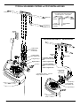
1
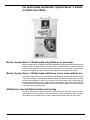
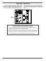
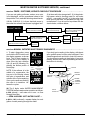
Water Softener Model MSD45E How to install, operate and maintain your Demand Controlled Water Softener Do not return water softener to store If you have questions or concerns when installing, operating or maintaining your water softener, call our toll free number: 1--888--64 WATER (1--888--649--2837) Monday -- Friday 8 AM -- 7 PM EST or visit www.systemsaver.com When you call, please be prepared to provide the model, date code and serial number of your product, located on the rating decal on back of the top cover. Systems tested and certified by NSF International against NSF/ANSI Standard 44 for hardness reduction and efficiency. For best results use Mortonr System Saverr II Pellets in your softener. Printed on recycled paper 7324049 (Rev. D 1/27/11) For best results use Mortonr System Saverr II Pellets to Soften Your Water Mortonr System Saverr II Pellets make a big difference in your water. Mortonr System Saverr II Pellets are specially formulated to consistently outperform other water softening salts in all water softeners. System Saverr II Pellets enable your water softener to remove almost twice as much dirt and impurities and up to 5% more minerals from your water than plain salt pellets. And that can mean a big difference in the quality of your water. Mortonr System Saverr II Pellets make a difference in your water softener, too. Hard water contains traces of dirt, iron and other minerals that can build up in the resin and valves of your water softener. That can lead to expensive repairs. But Mortonr System Saverr II Pellets are specially formulated to clean out those traces of dirt and minerals and to help keep your softener clean and problem free -- longer than all other salt pellets. System Saverr II Pellets are formulated with salt that is guaranteed 99.5% pure and contains virtually no insolubles that need to be cleaned from your brine tank. With Morton, Your Soft Water Solution is in the Bag. Mortonr System Saverr II Pellets come in a handy yellow 40--lb. bag that’s easy to lift, carry, open and pour. The easy--open pull--tab opens just wide enough to allow salt to pour out easily, yet enables you to regulate the flow. And the sturdy handle makes it easy for you to carry. 2 Mortonr System Saverr Installation & Operation Manual TABLE OF CONTENTS PAGE NO. WARRANTY . . . . . . . . . . . . . . . . . . . . . . . . . . . . . . . . . . . . . . . . . . . . . . . . . . . . . . . . . . . . . . . . . . . . . . . . BEFORE YOU START . . . . . . . . . . . . . . . . . . . . . . . . . . . . . . . . . . . . . . . . . . . . . . . . . . . . . . . . . . . . . . . UNPACKING / INSPECTION . . . . . . . . . . . . . . . . . . . . . . . . . . . . . . . . . . . . . . . . . . . . . . . . . . . . . . . . . SPECIFICATIONS / DIMENSIONS . . . . . . . . . . . . . . . . . . . . . . . . . . . . . . . . . . . . . . . . . . . . . . . . . . . . BEFORE STARTING INSTALLATION . . . . . . . . . . . . . . . . . . . . . . . . . . . . . . . . . . . . . . . . . . . . . . . . . . TYPICAL INSTALLATION ILLUSTRATION . . . . . . . . . . . . . . . . . . . . . . . . . . . . . . . . . . . . . . . . . . . . . INSTALLATION STEPS . . . . . . . . . . . . . . . . . . . . . . . . . . . . . . . . . . . . . . . . . . . . . . . . . . . . . . . . . . . . . . PROGRAMMING THE MORTON WATER SOFTENER . . . . . . . . . . . . . . . . . . . . . . . . . . . . . . . . . . SANITIZING PROCEDURES . . . . . . . . . . . . . . . . . . . . . . . . . . . . . . . . . . . . . . . . . . . . . . . . . . . . . . . . . WATER CONDITIONING INFORMATION . . . . . . . . . . . . . . . . . . . . . . . . . . . . . . . . . . . . . . . . . . . . . . GENERAL WATER SOFTENER MAINTENANCE . . . . . . . . . . . . . . . . . . . . . . . . . . . . . . . . . . . . . . . MORTON WATER SOFTENER FEATURES & SETTINGS . . . . . . . . . . . . . . . . . . . . . . . . . . . . . . . . MORTON WATER SOFTENER SERVICE . . . . . . . . . . . . . . . . . . . . . . . . . . . . . . . . . . . . . . . . . . . . . . REPAIR PARTS . . . . . . . . . . . . . . . . . . . . . . . . . . . . . . . . . . . . . . . . . . . . . . . . . . . . . . . . . . . . . . . . . . . . . 3 4 5 6 7 8 9 -- 11 12 -- 13 13 14 15 -- 16 17 -- 20 21 -- 23 24 -- 27 WARRANTY MORTON RESIDENTIAL WARRANTY Morton guarantees to the original owner, that: One Year Full Warranty: For a period of one (1) year after installation, all parts will be free of defects in material and workmanship and will perform their normal functions. For a period of one (1) year after installation, labor to repair any part deemed to be defective in materials or workmanship, will be provided at no additional cost. Limited Warranties: For a period of ten (10) years from date of purchase, the salt storage tank and fiberglass mineral tank will not rust, corrode, leak, burst, or in any other manner, fail to perform their proper functions; and that For a period of three (3) years after installation, electronic control board will be free of defects in material and workmanship and will perform its normal functions. If, during such respective period, a part proves to be defective, Morton will ship a replacement part, directly to your home, without charge. Labor necessary to maintain this product is not covered by the product warranty. If you have questions regarding a Morton product, need assistance with installation or trouble shooting, wish to order a part or report a warranty issue, we are just a phone call away. Simply dial 1--888--64--WATER (1--888--649--2837) for assistance, or visit www.systemsaver.com. This water softener is manufactured for Morton, P.O. Box 25290, Woodbury, MN 55125--0290 General Provisions The above warranties are effective provided the water conditioner is operated at water pressures not exceeding 125 psi, and at water temperatures not exceeding 120F; provided further that the water conditioner is not subject to abuse, misuse, alteration, neglect, freezing, accident or negligence; and provided further that the water conditioner is not damaged as the result of any unusual force of nature such as, but not limited to, flood, hurricane, tornado or earthquake. Morton is excused if failure to perform its warranty obligations is the result of strikes, government regulation, materials shortages, or other circumstances beyond its control. *THERE ARE NO WARRANTIES ON THE WATER CONDITIONER BEYOND THOSE SPECIFICALLY DESCRIBED ABOVE. ALL IMPLIED WARRANTIES, INCLUDING ANY IMPLIED WARRANTY OF MERCHANTABILITY OR OF FITNESS FOR A PARTICULAR PURPOSE, ARE DISCLAIMED TO THE EXTENT THEY MIGHT EXTEND BEYOND THE ABOVE PERIODS. THE SOLE OBLIGATION OF MORTON UNDER THESE WARRANTIES IS TO REPLACE OR REPAIR THE COMPONENT OR PART WHICH PROVES TO BE DEFECTIVE WITHIN THE SPECIFIED TIME PERIOD, AND MORTON IS NOT LIABLE FOR CONSEQUENTIAL OR INCIDENTAL DAMAGES. NO MORTON DEALER, AGENT, REPRESENTATIVE, OR OTHER PERSON IS AUTHORIZED TO EXTEND OR EXPAND THE WARRANTIES EXPRESSLY DESCRIBED ABOVE. Some states do not allow limitations on how long an implied warranty lasts or exclusions or limitations of incidental or consequential damage, so the limitations and exclusions in this warranty may not apply to you. This warranty gives you specific legal rights, and you may have other rights which vary from state to state. This warranty applies to consumer--owned installations only. Mortonr System Saverr Installation & Operation Manual 3 BEFORE YOU START FOLLOW THE INSTALLATION INSTRUCTIONS CAREFULLY. FAILURE TO INSTALL THE SOFTENER PROPERLY VOIDS THE WARRANTY. BEFORE YOU BEGIN INSTALLATION, READ THIS ENTIRE MANUAL. THEN, OBTAIN ALL THE MATERIALS AND TOOLS YOU WILL NEED TO MAKE THE INSTALLATION. CHECK LOCAL PLUMBING AND ELECTRICAL CODES. THE INSTALLATION MUST CONFORM TO THEM. CODES IN THE STATE OF MASSACHUSETTS REQUIRE INSTALLATION BY A LICENSED PLUMBER. FOR INSTALLATION, USE PLUMBING CODE 248--CMR OF THE COMMONWEALTH OF MASSACHUSETTS. USE ONLY LEAD--FREE SOLDER AND FLUX FOR ALL SWEAT--SOLDER CONNECTIONS, AS REQUIRED BY STATE AND FEDERAL CODES. USE CARE WHEN HANDLING THE SOFTENER. DO NOT TURN UPSIDE DOWN, DROP, OR SET ON SHARP PROTRUSIONS. DO NOT LOCATE THE SOFTENER WHERE FREEZING TEMPERATURES OCCUR. DO NOT ATTEMPT TO TREAT WATER OVER 120F. FREEZING, OR HOT WATER DAMAGE VOIDS THE WARRANTY. AVOID INSTALLING IN DIRECT SUNLIGHT. EXCESSIVE SUN HEAT MAY CAUSE DISTORTION OR OTHER DAMAGE TO NON--METALLIC PARTS. THE SOFTENER REQUIRES A MINIMUM WATER FLOW OF 3 GALLONS PER MINUTE AT THE INLET. MAXIMUM ALLOWABLE INLET WATER PRESSURE IS 125 PSI. IF DAYTIME PRESSURE IS OVER 80 PSI, NIGHTTIME PRESSURE MAY EXCEED THE MAXIMUM. USE A PRESSURE REDUCING VALVE IF NECESSARY. ( ADDING A PRESSURE REDUCING VALVE MAY REDUCE THE FLOW.) THE SOFTENER WORKS ON 24 VOLT, 60 Hz ELECTRICAL POWER ONLY, SUPPLIED BY A DIRECT PLUG--IN TRANSFORMER (INCLUDED). BE SURE TO USE THE INCLUDED TRANSFORMER AND PLUG IT INTO A NOMINAL 120V, 60 CYCLE HOUSEHOLD OUTLET THAT IS GROUNDED AND PROPERLY PROTECTED BY AN OVER CURRENT DEVICE SUCH AS A CIRCUIT BREAKER OR FUSE. IF TRANSFORMER IS REPLACED, USE ONLY UL, CUL OR CSA APPROVED CLASS 2 TRANSFORMER WITH THE FOLLOWING SPECIFICATIONS: -- INPUT: 120 VAC, 60 Hz, 13.5 W -- OUTPUT VOLTAGE: 24 VAC -- OUTPUT CURRENT: 400mA THIS SYSTEM IS NOT INTENDED TO BE USED FOR TREATING WATER THAT IS MICROBIOLOGICALLY UNSAFE OF OF UNKNOWN QUALITY WITHOUT ADEQUATE DISINFECTION BEFORE OR AFTER THEY SYSTEM. EUROPEAN DIRECTIVE 2002/96/EC REQUIRES ALL ELECTRICAL AND ELECTRONIC EQUIPMENT TO BE DISPOSED OF ACCORDING TO WASTE ELECTRICAL AND ELECTRONIC EQUIPMENT (WEEE) REQUIREMENTS. THIS DIRECTIVE OR SIMILAR LAWS ARE IN PLACE NATIONALLY AND CAN VARY FROM REGION TO REGION. PLEASE REFER TO YOUR STATE AND LOCAL LAWS FOR PROPER DISPOSAL OF THIS EQUIPMENT. 4 Mortonr System Saverr Installation & Operation Manual UNPACKING / INSPECTION The parts required to assemble and install the unit are included in a bag. Thoroughly check the water softener for possible shipping damage and parts loss. Also note damage to the shipping cartons. Remove and discard (or recycle) all packing materials. To avoid loss of the small parts, we suggest you keep them in the parts bag until you are ready to use them. 1 spare clip included Do not return the water softener to store. If you have any questions, or there are missing parts or damage, please call Toll Free 1---888---64WATER (1---888---649---2837). When you call, please be prepared to provide the model, date code and serial number of your product, located on the rating decal on back of the top cover. For more installation or service information visit www.systemsaver.com. Mortonr System Saverr Installation & Operation Manual 5 SPECIFICATIONS / DIMENSIONS MSD45E 13,300 @ 2.6 35,700 @ 9.9 45,400 @ 17.2 RATED EFFICIENCY (grains / lb @ min. salt dose) H 5120 @ 2.6 AMOUNT OF HIGH CAPACITY RESIN (lbs / cu ft) 65.5 / 1.26 RESIN TANK NOMINAL SIZE (in., dia x height) SERVICE FLOW RATE (gpm) INLET -- OUTLET 11 INTERMITTENT FLOW RATE @ 15 psi (gpm) Y 12.3 WATER SUPPLY MAXIMUM HARDNESS (gpg) 120 WATER SUPPLY MAX. CLEAR WATER IRON (ppm) D 12 WATER PRESSURE LIMITS (min. / max. psi) z 20 --- 125 WATER TEMPERATURE LIMITS (_F) 40 --- 120 WATER SUPPLY MINIMUM FLOW RATE (gpm) 3--7/8” 10 x 40 10.0 PRESSURE DROP AT SERVICE FLOW (psi) 14” INLET RATED CAPACITY (grains @ lbs salt dose) OUT MODEL 18--1/4” 50--3/8” 41--5/8” 3 REGENERATION CYCLE FLOW RATES (gpm) FILL (flow to brine tank) .3 BRINING BRINE RINSE MAX. BACKWASH MAX. FAST RINSE 0.22 (flow to drain) 0.15 2.0 2.0 This system conforms to NSF/ANSI 44 for specific performance claims as verified and substantiated by test data. H Efficiency rating is only valid at the lowest salt dosage. These softeners were efficiency rated according to NSF/ANSI Standard 44. Y Intermittent flow rate does not represent the maximum service flow rate used for determining the softeners rated capacity and efficiency. Continuous operation at flow rates greater than the service flow rate may affect capacity and efficiency performance. D Capacity to reduce clear water iron is substantiated by WQA test data. z Canada working pressure: 1.4 -- 7.0 kg/cm@. 6 Mortonr System Saverr Installation & Operation Manual BEFORE STARTING INSTALLATION " WHERE TO INSTALL THE SOFTENER . . . . . . . . . . . . . . . . . . . . . . . . . . . . . . . . . . . . . . . . . . . . . . . . Place the softener as close as possible to the pressure tank (well system) or water meter (city water). Place the softener as close as possible to a floor drain, or other acceptable drain point (laundry tub, sump, standpipe, etc.). Connect the softener to the main water supply pipe BEFORE or AHEAD OF the water heater. DO NOT RUN HOT WATER THROUGH THE SOFTENER. Temperature of water passing through the softener must be less than 120_F (49_C). Keep outside faucets on hard water to save soft water and salt. Do not install the softener in a place where it could freeze. Damage caused by freezing is not covered by the warranty. Put the softener in a place water damage is least likely to occur if a leak develops. The manufacturer will not repair or pay for water damage. A 120 volt electric outlet, to plug the included transformer into, is needed within 10 feet of the softener. The transformer has an attached 10 foot power cable. Be sure the electric outlet and transformer are in an inside location, to protect from wet weather. If installing in an outside location, you must take the steps necessary to assure the softener, installation plumbing, wiring, etc., are as well protected from the elements, contamination, vandalism, etc., as when installed indoors. Keep the softener out of direct sunlight. The sun’s heat may soften and distort plastic parts. " TOOLS, PIPE and FITTINGS, OTHER MATERIALS YOU WILL NEED . . . . . . . . . . . . . . . . . . . . GPlastic inlet and outlet fittings included with the softener allow water flow equivalent to 1” (nominal) pipe. To maintain full valve flow, 1” pipes to and from the softener fittings are recommended. You should maintain the same, or larger, pipe size as the water supply pipe, up to the softener inlet and outlet. GUse copper, brass, or galvanized pipe and fittings. Some codes may also allow PVC plastic pipe. GALWAYS install the included bypass valve, or 3 shut-off valves. Bypass valves let you turn off water to the softener for repairs if needed, but still have water in the house pipes. GA length of 3/8” inside diameter flexible hose is provided for the valve drain. See step 6 on page 10. NOTE: Avoid drain hose runs longer than 30 feet. Avoid elevating the hose more than 8 feet above the floor. Make the valve drain line as short and direct as possible. GIf local codes do not allow use of a flexible drain hose, a rigid valve drain run must be used. Purchase a compression fitting (1/4 NPT x 1/2” minimum tube) and 1/2” copper tubing from your local hardware store. Plumb a rigid drain line as needed (See Figure 3 on page 10). Comply with plumbing codes. GA length of 3/8” inside diameter hose is provided for the salt tank drain. See step 7 on page 11. If a longer length is needed, you can buy good quality, thick-wall, flexible hose at most hardware stores or supply houses. GNugget or pellet water softener salt is needed to fill the brine tank (see page 11 and 15). " PLAN HOW YOU WILL INSTALL THE SOFTENER . . . . . . . . . . . . . . . . . . . . . . . . . . . . . . . . . . . . . You must first decide how to run in and out pipes to the softener. Look at the house main water pipe at the point where you will connect the softener. Is the pipe soldered copper, glued plastic, or threaded brass/galvanized? What is the pipe size? Now look at the typical installation illustration on page 6. Use it as a guide when planning your particular installation. Be sure to direct raw, hard water to the softener valve inlet fitting. The valve is marked IN and OUT. Mortonr System Saverr Installation & Operation Manual 7 TYPICAL SOLDERED COPPER or CPVC INSTALLATIONS soft water CROSS -- OVER Use if water supply flows from the left. Include single or 3 -- valve bypass. hard water hard water to outside faucets HARD WATER SOFT WATER FROM SOFTENER OUTLET TO SOFTENER INLET 120 Volt outlet INSTALLATION USING 3 -- VALVE BYPASS 1” NPT sweat adaptor (2) not included 1” NPT installation adaptor (2) * o--ring seal (2) * Bypass Valve * clip (4) * BYPASS valve OUTLET valve INLET valve D for soft water SERVICE: - Open the inlet and outlet valves. - Close the bypass valve. D for hard water BYPASS: - Close the inlet and outlet valves. - Open the bypass valve. * included with softener -- Pipe and fittings supplied by installer. 1” NPT sweat adaptor (2) not included clip (2) * 1” NPT installation adaptor (2) * o--ring seal (2) * VALVE INLET 8 Mortonr System Saverr Installation & Operation Manual INSTALLATION STEPS 1. INSTALL BYPASS VALVE and/or PLASTIC INSTALLATION ADAPTORS: NOTE: Before installing the bypass valve or plastic installation adaptors, be sure the turbine and support are firmly in place, in the valve outlet. Blow into the valve port and observe the turbine for free rotation. turbine support FIGURE 1 A clip (2) plastic installation adaptors (install in softener valve or bypass valve) sensor port OUTLET turbine " Push the bypass valve, with lubricated o--ring seals in place, into the valve inlet and outlet ports, Figures 1A and 1C. INLET -- AND/OR -- " Slide plastic installation adaptors, with lubricated o--ring seals in place, into the softener valve or bypass valve inlet and outlet ports, Figure 1A. " Snap the two large plastic clips in place, from the top down, Figures 1A and 1B. Be sure they snap into place. Pull on the plastic installation adaptors, or bypass valve, to make sure they are held securely in place. clip (2) bypass valve B bypass valve or plastic adaptor clip cross section of valve inlet or outlet 2. INSTALL THE BRINE TANK OVERFLOW FITTINGS: " Insert the rubber grommet into the 3/4” diameter hole in the brine tank sidewall, see page 11. " Push the barbed end of the hose adaptor elbow into the grommet. 3. MOVE THE SOFTENER ASSEMBLY (CABINET MODEL), OR RESIN TANK (TWO TANK MODEL) INTO INSTALLATION POSITION: " Be sure the installation surface is level and smooth. If needed, place the tank on a section of 3/4” thick (min.) plywood. Then, place shims under the plywood as needed to level the softener. clip snaps into place between larger diameter rings C o--ring Bypass Valve turned downward for connection to floor level plumbing. 4. PLUMB IN AND OUT PIPES TO AND FROM SOFTENER: CAUTIONS: Observe all of the following cautions while you connect inlet and outlet plumbing. " Shut off the electric or fuel supply to the water heater. " Turn off the house water supply valve and open faucets to relieve pressure in the pipes. " BE SURE RAW, HARD WATER IS DIRECTED TO THE VALVE INLET PORT. " Be sure to use bypass valve(s). IN OUT NOTE: CHECK LOCAL PLUMBING AND ELECTRICAL CODES. THE INSTALLATION MUST CONFORM TO THEM. In Massachusetts, plumbing codes of Massachusetts shall be adhered to. Consult with your licensed plumber. Mortonr System Saverr Installation & Operation Manual 9 INSTALLATION STEPS, continued " If making a soldered copper installation, do all sweat soldering before connecting pipes to the softener fittings. Torch heat will damage plastic parts. " When turning threaded pipe fittings onto plastic fittings, use care not to cross--thread. " Use pipe joint compound on all external pipe threads. " Support inlet and outlet plumbing in some manner (use pipe hangers) to keep the weight off of the valve fittings. 5. INSTALL GROUNDING WIRE (IF NEEDED): " To maintain electrical ground continuity in the house cold water piping, install a #4 copper wire across the removed section pipe, securely clamping it at both ends (see Figure 2) -- parts not included. FIGURE 2 hose clamp ground (2) ground wire inlet -- outlet pipes FIGURE 3 drain fitting adaptor 6. CONNECT AND RUN THE VALVE DRAIN HOSE: " Measure, cut to length and connect the 3/8” flexible drain hose (provided) to the valve drain fitting. Use a hose clamp to hold the hose in place. NOTE: If codes require a rigid drain line, see “Connecting a Rigid Valve Drain Tube” in Figure 3. " Locate the other end of the hose at a suitable drain point...floor drain, sump, laundry tub, etc. Check and comply with local codes. IMPORTANT: If a longer length of hose is needed, buy and use high quality, thick--wall hose that will not easily kink or collapse. The water softener will not work if water cannot exit this hose during regenerations. " Tie or wire the hose in place at the drain point. Water pressure will cause it to whip during the backwash and fast rinse cycles of regeneration. Also provide an air gap of at least 1--1/2” between the end of the hose and the drain point. An air gap prevents possible siphoning of sewer water, into the softener, if the sewer should back up. " If raising the drain hose overhead is required to get to the drain point, do not raise higher than 8’ above the floor. Elevating the hose may cause a back--pressure that could reduce brine draw during regenerations. continued CONNECTING A RIGID VALVE DRAIN TUBE PULL OUT for soft water ‘‘service’’ PUSH IN for bypass To adapt a copper drain tube to the softener, buy a compression fitting (1/4 NPT x 1/2”O.D. minimum tube) and needed tubing from your local hardware store. Compression fitting 1/4 NPT x 1/4” NPT thread 1/2” O.D. tube barbs Clip valve drain hose Cut barbs from valve drain elbow (pull clip and remove drain valve elbow from valve) valve drain hose overflow drain hose 1--1/2” air gap 10 To standpipe, sump, laundry tub or other approved drain. 1--1/2” air gap FLOOR DRAIN 1/2” outside diameter copper tube LAUNDRY TUB 1--1/2” air gap SUMP STANDPIPE 1--1/2” air gap Mortonr System Saverr Installation & Operation Manual INSTALLATION STEPS, continued 7. CONNECT AND RUN THE BRINE TANK OVERFLOW HOSE: This drain is for safety only. If the brine tank should over--fill with water, the excess is carried to the drain. " Attach a length of flexible hose (included) to the drain elbow, installed in step 2, page 9. Use a hose clamp to hold it in place. " Locate the other end of the hose at the drain point. Do not elevate this hose higher than the elbow on the brine tank. Do not tee this hose to the valve drain hose. 8. FLUSH PIPES, EXPEL AIR FROM SOFTENER, AND TEST YOUR INSTALLATION FOR WATER LEAKS: CAUTION: To avoid water or air pressure damage to softener inner parts, be sure to do the following steps exactly as listed. A. Fully open two cold, soft water faucets nearby the softener. B. Place bypass valve(s) in ‘‘bypass’’ position. On a single valve, slide the stem inward to BYPASS, see page 10. On a 3--valve system, close the inlet and outlet valves, and open the bypass valve, see page 8. C. Fully open the house main water pipe shutoff valve. Observe a steady flow from both opened faucets. D. Place bypass valve(s) in ‘‘service”, EXACTLY as follows. KEEP SOFT WATER FAUCETS OPEN. 1. SINGLE BYPASS VALVE: SLOWLY, pull the valve stem outward to ‘‘service’’, pausing several times to allow the softener to pressurize slowly. 2. 3--VALVE BYPASS: Fully close the bypass valve and open the outlet valve. SLOWLY, open the inlet valve, pausing several times to allow the softener to pressurize slowly. E. After about three minutes, open a HOT water faucet for one minute, or until all air is expelled, then close. F. Close both cold water faucets. G. Check your plumbing work for leaks and fix right away, if any are found. Be sure to observe previous caution notes. H. Turn on the gas or electric supply to the water heater. Light the pilot, if applicable. 9. ADD WATER AND SALT TO THE BRINE TANK: " Remove the salt storage area cover. Add about three gallons of water into the tank. Do not add into the brinewell. " Fill the tank with NUGGET, PELLET or coarse SOLAR water softener salt. Do not use rock, block, and ice cream making salts. For best results, we recommend MortonR System SaverR II Pellets for use in this water softener. Note: If the softener is installed in a humid basement or other damp area, it is better to fill the tank with less salt, more frequently (see salt bridging in the maintenance section). Eighty to 100 lbs of salt will last for several months, depending on water hardness, family size, and model of softener. 10. CONNECT TO ELECTRICAL POWER: " The softener works on 120 volt, 60 Hz electric power. The included transformer changes standard 120 volt AC house power to 24 volts. Plug the transformer into a 120 volt outlet only. Be sure the outlet is always ‘‘live’’ so it can not be switched off by mistake. 11. PROGRAM THE MORTON WATER SOFTER ELECTRONIC CONTROL, page 12. Questions? Call Toll Free 1--888--64 WATER (1-- 888-- 649-- 2837) Monday--Friday, 8 AM -- 7 PM EST or visit www.systemsaver.com When you call, please be prepared to provide the model, date code and serial number, located on the rating decal on back of the top cover. Mortonr System Saverr Installation & Operation Manual 11 PROGRAMMING THE MORTON WATER SOFTENER RECHARGE button display up button down button Water Softener DATA button " ELECTRONIC CONTROL SETTINGS REQUIRED...upon installation, and after an extended power outage (see Program Memory, page 18). NOTES: D WHEN THE TRANSFORMER IS PLUGGED INTO THE ELECTRICAL OUTLET (STEP 10, PAGE 11), 12:00PM (flashing), and PRESENT TIME show in the upper display area. Program the electronic control as follows. If A - - - is flashing, please see Model Code setting on page 20. D A ‘‘beeper’’ sounds while pressing buttons for electronic control programming. One beep signals a change in the display. Repeated beeps means the electronic control will not accept a change from the button you have pressed, and you should use another. D To program the electronic control, you will use either the SELECT, UP or DOWN buttons. " SET PRESENT TIME OF DAY . . . . . . . . . . . . . . . . . . . . . . . . . . . . . . . . . . . . . . . . . . . . . . . . . . . . . . . . NOTE: If the words PRESENT TIME do not show in the display, press the SELECT button until they do. 1. Press either the SELECT, UP or DOWN button to set. The UP button moves the display ahead; the DOWN button moves the time backward. PM If the present time is between NOTE: Each press of the UP or DOWN button noon and midnight, be sure PM changes the time by one minute. Holding the butPRESENT TIME shows. tons in changes the time 32 minutes each second. If the present time is between 2. When the present time shows, press SELECT midnight and noon, be sure AM to apply. shows. 12 Mortonr System Saverr Installation & Operation Manual PROGRAMMING THE MORTON WATER SOFTENER, continued " SET WATER HARDNESS NUMBER . . . . . . . . . . . . . . . . . . . . . . . . . . . . . . . . . . . . . . . . . . . . . . . . . . . NOTE: If 25 (factory default) and HARDNESS do not show in the display, press the SELECT button until they do. 1. Press either the SELECT, UP or DOWN button to set your water hardness number in the display. You can get the grains per galThe DOWN button moves the display down to 1. lon (gpg) hardness of your waThe UP button moves the display up to 95,110, or ter supply from a water analysis HARDNESS 120, depending on the model code. laboratory, or call and ask your local water department, if you NOTE: Each press of the UP or DOWN button are on a municipal supply. changes the display by 1 between 1 and 25. Above If your water supply contains 25, the display changes 5 at a time; 25, 30, 35, etc. ferrous (clear water) iron, inHolding a button in changes the numbers twice crease the hardness setting to each second. compensate for it as follows: 2. When your water hardness number shows, Add 5 to the hardness number press SELECT to apply. for each 1 ppm of iron. The special features of your water softener are explained on pages 17-- 20. TO COMPLETE THE INSTALLATION, DO THE SANITIZING BELOW. SANITIZING PROCEDURES Care is taken at the factory to keep your water softener clean and sanitary. Materials used to make the softener will not infect or contaminate your water supply, and will not cause bacteria to form or grow. However, during shipping, storage, installing and operating, bacteria could get into the softener. For this reason, sanitizing as follows is suggestedw when installing. 1. Be sure to complete all installation steps, including electronic control programming. 2. Pour about 3/4 oz. of common 5.25% household bleach (Clorox, Linco, Bo Peep, White Sail, Eagle, etc.,) into the brinewell. 3. Start a recharge: Press the RECHARGE button and hold for 3 seconds, until RECHARGE NOW begins to flash in the display. This recharge draws the sanitizing bleach into and through the water softener to sanitize it. Any air remaining in the unit is purged to the drain. 4. After the recharge has completed, fully open a cold water faucet, downstream from the softener, and allow 50 gallons of water to pass through the system. This should take at least 20 minutes. Close the faucet. wNOTE: Sanitizing is recommended by the Water Quality Association for disinfecting. On some water supplies, they suggest periodic sanitizing. NOTE: When the above sanitizing regeneration is over, all remaining bleach is flushed from the conditioner and your house COLD water supply is fully soft immediately. However, your water heater is filled with hard water and, as hot water is used, it will refill with soft water. When all the hard water is replaced, in the water heater, hot only, and mixed hot and cold water will be fully soft. If you want totally soft water immediately, after the above regeneration, drain the water heater until the water runs cold. If you do drain the water heater, use extreme care as the hot water could cause severe burns. Mortonr System Saverr Installation & Operation Manual 13 WATER AND WATER CONDITIONING WATER CONDITIONING INFORMATION . . . . . . . . . . . . . . . . . . . . . . . . . . . . . . . . . . . . . . . . . . . . . . . . . IRON in water can cause stains on clothing and plumbing fixtures. It can negatively affect the taste of food, drinking water, and other beverages. Iron in water is measured in parts per million (ppm). The total* ppm of iron, and type or types*, is determined by chemical analysis. Four different types of iron in water are: ¡ Ferrous (clear water), © Ferric (red water), ¢ Bacterial and organically bound iron, £ Colloidal and inorganically bound iron (ferrous or ferric). Ferrous (clear water) iron is soluble and dissolves in water. This water softener will reduce moderate amounts of this type of iron (see specifications).** It is usually detected by taking a sample of water in a clear bottle or glass. Immediately after taking, the sample is clear. As the water sample stands, it gradually clouds and turns slightly yellow or brown as air oxidizes the iron. This usually occurs in 15 to 30 minutes. When using the softener to reduce Ferrous (clear water) iron , add 5 grains to the hardness setting for every 1 ppm of Ferrous (clear water) iron. See “Set Water Hardness Number” section. Ferric (red water), and Bacterial and organically bound irons are insoluble. This water softener will not remove ferric or bacterial iron. This iron is visible immediately when drawn from a faucet because it has oxidized before reaching the home. It appears as small cloudy yellow, orange, or reddish suspended particles. After the water stands for a period 14 of time, the particles settle to the bottom of the container. Generally these irons are removed from water by filtration. Chlorination is also recommended for bacterial iron. Colloidal and inorganically bound iron is of ferric or ferrous form that will not filter or exchange out of water. In some instances, treatment may improve colloidal iron water, but always CONSULT A QUALIFIED WATER CHEMISTRY LAB before attempting to treat it. Colloidal iron water usually has a yellow appearance when drawn. After standing for several hours, the color persists and the iron does not settle, but remains suspended in the water. Iron in water causes stains on clothing and plumbing fixtures. It negatively affects the taste of food, drinking water, and other beverages. SEDIMENT is fine, foreign material particles suspended in water. This water softener will not remove sediment. This material is most often clay or silt. Extreme amounts of sediment may give the water a cloudy appearance. A sediment filter installed upstream of the water softener normally corrects this condition. *Water may contain one or more of the four types of iron and any combination of these. Total iron is the sum of the contents. **Capacity to reduce clear water iron is substantiated by WQA test data. Mortonr System Saverr Installation & Operation Manual GENERAL WATER SOFTENER MAINTENANCE CHECKING THE SALT STORAGE LEVEL, AND ADDING SALT (also see page 11) . . . . . . . . . . Brine (salt dissolved in water) is needed for each and every regeneration. The water for making brine is metered into the salt storage area by the softener valve and electronic control. However, you must maintain a level of salt in the tank. In humid areas, it is best to add less salt, more often. WHEN TO ADD SALT: Check the salt level a few weeks after you install the softener and every week after that. Add when the brine tank is from 1/3 to 1/2 full. Never allow the softener to use all the salt before you add more. Without salt, you will soon have hard water. Use clean water softener salt only, at least 99.5% pure. NUGGET, PELLET or coarse SOLAR salts are recommended. Do not use rock, block, granulated, and ice cream making salts. They contain dirt and sediments, or mush and cake, and will create maintenance problems. For best results, we recommend MortonR System SaverR II Pellets for use in this water softener. BREAKING A SALT BRIDGE . . . . . . . . . . . . . . . . . . . . . . . . . . . . . . . . . . . . . . . . . . . . . . . . . . . . . . . . . . . Sometimes, a hard crust or salt bridge forms in the salt storage area. It is usually caused by high humidity or the wrong kind of salt. When the salt bridges, an empty space forms between the water and salt. Then salt will not dissolve in the water to make brine. If the brine tank is full of salt, it is hard to tell if you have a salt bridge. Salt is loose on top, but the bridge is under it. The following is the best way to check for a salt bridge. Salt should be loose all the way to the bottom of the tank. Take a broom handle, or like tool, and carefully push it down into the salt, working it up and down. If the tool strikes a hard object (be sure it’s not the bottom or sides of the tank), it’s most likely a salt bridge. Carefully break the bridge with the tool. DO NOT pound on the walls of the tank. push tool into salt bridge to break 1” -- 2” Pencil Mark Broom Handle Salt Salt Bridge Water Level If the wrong kind of salt made the bridge, take it out. Then fill the tank with nugget or pellet salt only. For best results, we recommend MortonR System SaverR II Pellets for use in this water softener. CLEANING IRON OUT OF THE WATER SOFTENER . . . . . . . . . . . . . . . . . . . . . . . . . . . . . . . . . . . . . . Your water softener takes hardness minerals (calcium and magnesium) out of the water. Also, it can control some (see specifications, page 6) “clear water” iron. With clear water iron, water from a faucet is clear when first put into a glass. After 15 to 30 minutes, the water begins to cloud or turn rust colored. A water softener WILL NOT remove any iron that makes the water cloudy or rusty as it comes from the faucet (called red water iron). To take red water iron out of water, or over the maximum of clear water iron, an iron filter or other equipment is needed. Your local dealer has trained people to help you with iron water problems. If your water supply has clear water iron, periodic resin bed cleaning is needed. Clean the bed at least every six months, or more often if iron appears in the soft water between treatments. Follow directions on the resin bed cleaner container. Mortonr System Saverr Installation & Operation Manual 15 GENERAL WATER SOFTENER MAINTENANCE, continued CLEANING THE NOZZLE AND VENTURI ASSEMBLY . . . . . . . . . . . . . . . . . . . . . . . . . . . . . . . . . . . . . A clean nozzle and venturi is needed for the softener to work right. This small unit makes the suction to move brine from the salt storage area to the resin tank during regeneration. If the nozzle and venturi becomes plugged with sand, silt, dirt, etc., the softener will not work and you will get hard water. To get to the nozzle and venturi, remove the softener top cover. Be sure the softener is in service cycle (no water pressure at nozzle and venturi). Then, while holding the nozzle & venturi housing with one hand, turn off the cap. Lift out the screen support and screen, then the nozzle and venturi. Wash and rinse the parts in warm water until clean. If needed, use a small brush to remove iron or dirt. Also check and clean the gasket. NOTE: Models in this manual have a small flow plug located in the nozzle and venturi, and a small cone shaped screen in the housing. Be sure to check and clean these parts. Carefully replace all parts in the correct order. Lubricate the o-ring seal with silicone grease and place in position. Install and tighten the cap, by hand only. Do not over-tighten and break the cap or housing. Cap O--ring Seal Screen Support Screen Nozzle & Venturi Gasket *Flow Plug (DUDC or DDUC) Screen IMPORTANT: Be sure small holes in the gasket are centered directly over the small holes in the nozzle & venturi housing. *Flow Plug (HVDC) Nozzle & Venturi Housing *Install with numbered side up, concave side down. SERVICE CHECKLIST NO SOFT WATER WATER INTERMITTENTLY HARD No salt in storage tank: See page 15 to refill, then start a regeneration, or recharge. Transformer unplugged at wall outlet, or disconnected from electronic control: Reconnect to electrical power and start a regeneration, or recharge. Fuse blown, circuit breaker popped, or circuit mistakenly switched off: Check and resolve as needed. Then, start a regeneration, or recharge. Plumbing bypass valve(s) in ‘‘bypass’’ position: Refer to page 8 or 10 and position valve(s) for ‘‘service’’ to direct soft water to house pipes. Then, start a regeneration, or recharge. Electronic control not programmed: See pages 12 and 13. Nozzle & venturi dirty, or salt in storage tank bridged: See page 15 and above to clean. Then, start a regeneration, or recharge. Possible increase in water hardness: See page 13. 16 Hot water used when softener is regenerating: The water heater will refill with hard water. Leaking faucet or toilet valve: A small leak will waste hundreds of gallons of water in just a few days. Fix all water leaks immediately. Mortonr System Saverr Installation & Operation Manual MORTON WATER SOFTENER FEATURES AND SETTINGS NOTE: SEE PAGES 12 and 13 TO SET THE CORRECT TIME OF DAY AND WATER HARDNESS NUMBER. NORMAL OPERATION, ELECTRONIC CONTROL DISPLAY . . . . . . . . . . . . . . . . . . . . . . . . . . . . . . . During normal operation, the present time of day, and AM or PM, show in the time display area. The demand computer determines when a regeneration is needed. Then, a regeneration will begin at the next regeneration start time PM feature: OTHER DATA DISPLAYS AM Fill RECHARGE NOW .................................................. With repeated presses of the DATA button, you can scan through four displays of operational information. This data appears in the bottom portion of the display area. These are: CAPACITY (remaining) -- This is the percentage of water softening capacity remaining. Immediately after a regeneration, 100% shows. Then, as water is used, the percentage decreases until the next regeneration. During regenerations, the percentage increments upward. (2:00AM or as you set it). RECHARGE NOW will flash until the regeneration is over. The display will also show the current cycle in the regeneration process. When the valve is in transition between cycles, both indicators flash. FLOW RATE, GPM* -- When using soft water, this display shows the gallon per minute flow rate passing through the softener. Zero shows if water is not in use. WATER MANAGEMENT SYSTEM GPM FLOW RATE WATER MANAGEMENT SYSTEM % CAPACITY NOTE: Zero (0%) shows until after the first regeneration begins, after connecting to electrical power. GALLONS* TODAY -- Each day, beginning at midnight, the electronic control keeps a running count of the total gallons of water passing through the softener. WATER MANAGEMENT SYSTEM GALLONS TODAY AVERAGE DAILY GALLONS* -- The figure displayed is the average gallons of water used by the household each day, over the past seven day period. WATER MANAGEMENT SYSTEM AVG DAILY GALLONS * If preferred, you can set the display to show the reading in liters instead of gallons, see page 20. If gallons today, or average daily gallons exceeds 1999, a (x 10) indicator appears. This means you must multiply the number shown times 10. feature: OPTIONAL RECHARGE CONTROLS . . . . . . . . . . . . . . . . . . . . . . . . . . . . . . . . . . . . . . . . . . . . Sometimes, a manually started regeneration (recharge) may be desired, or needed. Two examples are: ... You did not refill the storage tank with salt before it was all gone. ... You have used more water than usual (house guests, extra washing, etc.) and you may run out of soft water before the next regeneration. Use one of the following features to start a regeneration immediately, or at the next preset regeneration start time. continued Mortonr System Saverr Installation & Operation Manual 17 MORTON WATER SOFTENER FEATURES AND SETTINGS, continued RECHARGE NOW Press and hold in the RECHARGE button until RECHARGE NOW starts to flash in the time display area. The softener begins an immediate regeneration, and when over in about two hours, you will have a new supply of soft water. Once started, you cannot cancel this regeneration. RECHARGE TONIGHT Touch (do not hold) the RECHARGE button, and RECHARGE TONIGHT flashes in the time display area. A regeneration will occur at the next preset regeneration start time. If you decide to cancel this regeneration, before it has started, touch the same button once more. VACATION NOTE . . . . . . . . . . . . . . . . . . . . . . . . . . . . . . . . . . . . . . . . . . . . . . . . . . . . . . . . . . . . . . . . . . . . . . . . . . . . . The Morton Demand water softener regenerates only while water is used and softening capacity must be restored. For this reason, the softener will not regenerate when you are away from home for extended periods. feature: PROGRAM MEMORY . . . . . . . . . . . . . . . . . . . . . . . . . . . . . . . . . . . . . . . . . . . . . . . . . . . . . . . . . . If electrical power to the softener is interrupted, the time display is blank, but the electronic control keeps correct time for about 24 hours. When power is restored, you have to reset the present time only if the display is flashing. All other settings are maintained and never require resetting unless a change is desired. If the time is flashing after a long power outage, the softener continues to work as it should to provide you with soft water. However, regenerations may occur at the wrong time of day until you reset the electronic control to the correct time of day, page 12. setting: REGENERATION (STARTING) TIME, MAXIMUM DAYS BETWEEN REGENERATIONS, EFFICIENCY MODE, HEAVY DUTY BACKWASH AND 97% FEATURE . . . . . . . . . . . . . . . . . . . . . . NOTE: Each of these settings has a factory set default value. The defaults are: Regeneration start time -2:00AM; Maximum days between regenerations -- 0 (display shows dY --); Efficiency Mode -- OFF; 97% Feature -- OFF; Heavy duty backwash -- OFF. The defaults suit most installations. However, depending on water supply quality, household peak water use hours, etc., adjustment is available to meet specific needs. To make a change, read and do the following. continued 18 Mortonr System Saverr Installation & Operation Manual MORTON WATER SOFTENER FEATURES AND SETTINGS, continued REGENERATION (START) TIME: At the 2:00AM regeneration start time, the softener begins regenerations at that time. This is a good time in most households because water is not in use. If a different time would be better for your needs, do steps 1, 2, 4, 6, 8 and 10 to change the starting hour. MAXIMUM DAYS BETWEEN REGENERATIONS: The default setting allows the water softener to control regeneration frequency based on water usage readings from the water meter. It provides the most economical operation. You can set a maximum time (in days) between regenerations. For example, no more than 3 days will pass without a regeneration occurring if you set dY 3 in the display. A 1 to 15 day setting is available. To make a change from the default setting, do steps 1, 2, 3, 4, 6, 8 and 10. EFFICIENCY MODE: When this feature is ON, the unit will operate at salt efficiencies of 4000 grains of hardness per pound of salt or higher. (May recharge more often using smaller salt dosage and less water). When this is ON the efficiency icon will show in the lower right hand corner of the display. To make a change from the default setting, do steps 1, 2, 4, 5, 6, 8 and 10. CALIFORNIA EFFICIENCY REQUIREMENT Your water softener has a “High Efficiency” feature with an “ON” or “OFF” setting. This softener setting is shipped in the “OFF” position, which utilizes the maximum rated capacity while most often achieving maximum salt efficiencies. When installing this unit in the State of California, you MUST turn this setting to the “ON” position which may initiate more frequent recharges, however it will operate at 4000 grains per pound of salt or higher. If you wish to turn the Salt Efficiency feature “ON” ( icon will show in display), follow the instructions on this page. HEAVY DUTY BACKWASH: When set to ON, the backwash cycle of regeneration will be 10 minutes long instead of the normal 7 minute length. This is beneficial on some water supplies high in iron or sediment content. To conserve water, on clean supplies, be sure OFF shows. To change this setting, do steps 1, 2, 4, 6, 7, 8 and 10. SET 97% FEATURE: By setting to On, unit will automatically recharge when 97% capacity has been used, at any time of day. To change this setting, do steps 1, 2, 4, 6, 8, 9 and 10. 1. Beginning from the present time display, press and hold in the SELECT button until 2:00 AM begins to flash, RECHARGE TIME remains steady. AM RECHARGE TIME 2. Press the up or down button to display the desired start time. The up button moves the time ahead; the down button moves the time backward. Press the SELECT button to select time and move to next setting. up down 3. dY -- flashes, with RECHARGE remaining steady. Pressing the up button will increase the number of days, the down button will decrease the number of days. RECHARGE 4. Press the SELECT button to select and move to next setting. 5. On flashes and the efficiency mode icon shows in the lower right hand corner of the screen. Use the up or down buttons to toggle the efficiency mode either ON or OFF. E 6. Press the SELECT button to select and move to next setting. 7. HEAVY BACKWASH and flashing OFF shows in the display. Use the up or down buttons to toggle the heavy backwash either ON or OFF. Heavy Bkwash 8. Press the SELECT button to select and move to next setting. 9. Display toggles between 97 Recharge and OFF. Use the up or down buttons to toggle this setting either ON or OFF. RECHARGE 10. Press the SELECT button to select and return to the present time display. Mortonr System Saverr Installation & Operation Manual 19 MORTON WATER SOFTENER FEATURES AND SETTINGS, continued setting: MODEL CODE, 12 OR 24 HOUR CLOCK, AND GALLONS OR LITERS MEASURE . . . NOTE: The model code is factory set at assembly and testing. The hour clock and water measure have factory set default values. The defaults are: 12 or 24 hour clock -- 12; Gallons or liters measure -- gallons. The model code should never require resetting, but to check, or to set if previously omitted, read below. The defaults suit most installations. However, to make a change, read and do the following. MODEL CODE: The electronic control must have the right model code set to operate the softener correctly. The correct model code for model MSD45E is A 45. If A - - - is flashing in the display, do steps 2, 3, 5 and 7. To check for the correct code setting, and to reset if needed, do steps 1, 2, 3, 5 and 7. 12 OR 24 HOUR CLOCK: With 12 hr set, all time displays are in standard clock time, 12:00AM to 11:59PM. If 24 hr is set, time displays are in military time... 0100 (1:00AM) to 0000 (midnight). To change from the 12 hr setting, do steps 1, 3, 4, 5, and 7. GALLONS OR LITERS MEASURE: All water flow rate and usage displays are in gallons with the default GALS setting. If reset to litErs, the same displays are shown in liters. Use steps 1, 3, 5, 6 and 7 to change. 1. Beginning from the present AM time display, press and hold in RECHARGE the SELECT button until 2:00 TIME AM (or as otherwise set), and RECHARGE TIME begins to flash. 2. Press and hold in the SELECT button again. Either A --- -- or a previously set code will appear. If setting is needed, use the up or down button to set model code, as needed. 20 3. Press SELECT to select and move to next screen. 4. 12 hr flashes along with TIME. To change the display to 24 hr, use the up button. Use the down button to reset to 12 hr. TIME 5. Press SELECT to select and move to next screen. 6. GALS flashes, along with GALLONS. Use the up button to change to the liter setting. Use the down button to return to the gallon setting. GALLONS LITERS 7. Press the SELECT button a final time to return to the present time display. Mortonr System Saverr Installation & Operation Manual MORTON WATER SOFTENER SERVICE feature / service: AUTOMATIC ELECTRONIC DIAGNOSTICS . . . . . . . . . . . . . . . . . . . . . . . . . . . . . . The electronic control has a self--diagnostic function for the electrical system (except input power and water meter). The computer monitors the electronic components and circuits for correct operation. If a malfunction occurs, an error code appears in the display. The following chart shows the error codes that could appear, and possible defects for each code. While an error code is displayed, the RECHARGE and DATA buttons remain operable so you can perform the Manual Initiated Electronics Diagnostic. ERROR CODE DISPLAYED Err 01 POSSIBLE DEFECT Err 03 Err 04 ' motor inoperative ' wiring harness, or connection to switch ' switch ' valve defect causing high torque position Err 05 ' electronic control (PWA) TO REMOVE AN ERROR CODE: (1) unplug transformer (2) correct defect (3) plug transformer in (4) Wait for at least 12 minutes. The error code will return if the reason for the error code was not corrected. Mortonr System Saverr Installation & Operation Manual 21 MORTON WATER SOFTENER SERVICE, continued service: TIMER / SOFTENER, SERVICE CHECKOUT PROCEDURE . . . . . . . . . . . . . . . . . . . . . . . . If you are not getting soft water, and an error code is not displayed, use the procedures below to find the problem. First, make the following visual checks. VISUAL CHECKS: (1) Is there electrical power to the outlet the softener transformer is plugged into? NO SOFT WATER TIMER SHOWS WRONG TIME AND DAY, AND/OR IS FLASHING TIMER DISPLAY BLANK TIMER DISPLAY SHOWS CORRECT TIME AND DAY, AND IS STEADY Check electrical power to timer (outlet, transformer, power cable, all connections). (2) Is there salt in the storage tank? (3) Is the plumbing bypass valve(s) directing water for soft water service... see pages 6 and 8? (4) Is the valve drain hose open to the drain, not elevated too high, and unobstructed? If you do not find a problem with the visual checks, continue below. Electrical power was off. Reset the correct time of day. Investigate reason for power loss. Be sure outlet for softener cannot be switched off. NO POWER REPAIR AS NEEDED POWER OKAY TIMER DEFECTIVE Do manual diagnostics to verify proper function. Do manual diagnostics service: MANUAL INITIATED ELECTRONICS DIAGNOSTIC . . . . . . . . . . . . . . . . . . . . . . . . . . . . . . . 1. To enter diagnostics, press and hold the DATA button until the display appears as shown here. The dY and number, in the top part of the display, is days since the last recharge. See (A) and (B) following, explaining the bottom portion of the display. NOTE: If the softener is in the middle of a regeneration, the top part of the display shows the cycle of regeneration, and minutes of the cycle remaining. If two cycle names are flashing, the valve is in transition between the cycles. On LAST RECHARGE WATER MANAGEMENT SYSTEM TURBINE switch turbine count valve minutes of cycle position remaining MOTOR Fill TIME WATER MANAGEMENT SYSTEM POSITION SWITCH TURBINE SENSOR HOUSING TURBINE TURBINE SUPPORT & SHAFT (A) The 3 digits, under WATER MANAGEMENT SYSTEM, indicate water meter operation as follows: ' 000 (steady) = soft water not in useno flow through the meter. — OPEN A NEARBY SOFT WATER FAUCET — ' 000 to 140 (continual) = repeats display for each gallon of water passing through the meter. 22 If you don’t get a reading in the display, with faucet open, pull the sensor from the valve outlet port. Pass a small magnet back and forth in front of the sensor. You should get a reading in the display. If you get a reading, unhook the in and out plumbing and check the turbine for binding. VALVE OUTLET Mortonr System Saverr Installation & Operation Manual MORTON WATER SOFTENER SERVICE, continued (B) This display segment ( ), in the following table, indicates an open POSITION switch. The other indicates a closed switch. Use the RECHARGE button to manually advance the valve into each cycle and check correct switch operation. CORRECT SWITCH DISPLAYS VALVE CYCLE STATUS Valve in service, fill, brining, backwash or fast rinse position. Valve rotating from one position to another. 2. Press the DATA button again. This diagnostic display, shows the total number of recharges (top) since the timer was connected to electrical power. RECHARGE WATER MANAGEMENT SYSTEM DAY The number of days since the timer was connected to electrical power, is shown in the bottom part of the display. If over 1999 days, a (x 10) indicator shows, meaning you must multiply the number shown times 10. 3. Press DATA once again to return the present time to the display. service: MANUAL ADVANCE REGENERATION CHECK . . . . . . . . . . . . . . . . . . . . . . . . . . . . . . . . . . . . . This check verifies proper operation of the valve motor, brine tank fill, brine draw, regeneration flow rates, and other timer -- valve functions. First, make the initial checks, and the manual initiated diagnostics. NOTE: The face plate display must show a steady time (not flashing). 1. Press the RECHARGE button and hold in for 3 seconds. RECHARGE NOW begins to flash as the softener enters the fill cycle of regeneration. Remove the brinewell cover and, using a flashlight, observe fill water entering the brine tank. ' If water does not enter the tank, look for an obstructed nozzle, venturi, fill flow plug, brine tubing, or brine valve riser pipe. 2. After observing fill, press the RECHARGE button to move the softener into brining. A slow flow of water to the drain will begin. Verify brine draw from the brine tank by shining a flashlight into the brinewell and observing a noticeable drop in the liquid level. NOTE: Be sure a salt bridge is not preventing water with salt contact. ' If the softener does not draw brine nozzle and/or venturi dirty or defective. nozzle and venturi not seated properly on gasket. restricted drain (check drain fitting and hose). defective nozzle and venturi seal. other inner valve defect (rotor seal, rotor & disc, wave washer, etc.). 3. Press RECHARGE to move the softener into fast rinse. Again look for a fast drain flow. Allow the softener to rinse for a few minutes to flush out any brine that may remain in the resin tank from the brining cycle test. 4. To return the softener to service, press RECHARGE. Need help troubleshooting? Call Toll Free 1-- 888-- 64 WATER (1-- 888-- 649-- 2837) Monday--Friday, 8 AM -- 7 PM EST or visit www.systemsaver.com When you call, please be prepared to provide the model, date code and serial number, located on the rating decal on back of the top cover. Mortonr System Saverr Installation & Operation Manual 23 REPAIR PARTS 15 16 13 14 17 12 18 Valve Assembly 19 (see pages 26 and 27) 20 1 2 3 4 5 11 21 27 6 7 22 10 8 28 23 29 9 30 25 34 26 33 32 24 24 31 Mortonr System Saverr Installation & Operation Manual REPAIR PARTS KEY NO. PART NO. 1 7176292 2 7088033 KEY NO. PART NO. Clamp Section (2 req.) 18 7155115 Brinewell Cover Clamp Retainer (2 req.) 19 7082150 Wing Nut, 1/4 -- 20 O--ring Seal Kit 20 7100819 Brinewell DESCRIPTION DESCRIPTION 3 7112963 4 -- O--ring Seal, 2--7/8 in. x 3--1/4 in. 21 7003847 O--ring 5 -- O--ring Seal, 13/16 in. x 1--1/16 in. 22 7148875 Screw 6 -- O--ring Seal, 2--3/4 in. x 3 in. 23 7161831 Repl. Brine Tank 1103200 Hose Adaptor 7 7077870 Top Distributor 24 8 7105047 Repl. Bottom Distributor 25 9003500 Grommet 9 0502272 Resin, 53 lbs (1 cu ft) 26 0900431 Hose Clamp 10 7161849 Resin Tank, 9 in. dia x 40 in. 27 7310210 Brine Valve Assembly 11 7265025 Filter Screen 28 7221746 Brine Tube 7221754 Float, Stem & Guide Assembly 12 7189449 Bottom Cover 29 13 7174868 Faceplate Cover (order decal below) 30 7116713 Clip z 7310901 Decal, Faceplate 31 7308881 Brine Valve Body 14 7310969 Repl. Electronic Control Board (PWA) 32 7142942 Clip 7131365 Screen 15 7275907 Transformer 33 16 7192785 Salt Hole Cover 34 7113016 Tubing Assembly 17 7178626 Rim z 7139999 Drain Tubing z not illustrated. Questions? Call Toll Free 1--888--64 WATER (1-- 888-- 649-- 2837) Monday--Friday, 8 AM -- 7 PM EST or visit www.systemsaver.com When you call, please be prepared to provide the model, date code and serial number, located on the rating decal on back of the top cover. Mortonr System Saverr Installation & Operation Manual 25 REPAIR PARTS 50 51 94 52 93 53 92 54 55 56 91 57 89 60 90 88 63 cross--section view 85 70 95 62 seal 86 58 61 wear--strip 87 59 64 75 65 84 72 70 66 83 82 76 67 68 69 71 81 72 80 77 79 26 73 74 78 Mortonr System Saverr Installation & Operation Manual REPAIR PARTS KEY NO. PART NO. KEY NO. PART NO. 50 7224087 Screw, #8-32 x 1 in. (2 req.) 78 7171145 Valve Body 51 7286039 Motor (incl. 2 ea. of Key No. 50) 79 7170319 O-ring, 1/4 in. x 3/8 in. (2 req.) 52 7231393 Motor Plate 53 0900857 Screw, #6-20 x 3/8 in. (3 req.) 7253808 Nozzle & Venturi Asm. (incl. Key Nos. 80 & 82--89) 54 7171250 Bearing 80 7081104 Housing, Nozzle & Venturi 55 7283489 Cam and Gear 81 1202600 Nut — Ferrule 56 7169180 Clip (Drain) 82 7095030 Cone Screen 57 0900431 Hose Clamp 83 1148800 Flow Plug, .3 gpm 58 7271270 Drain Hose Adaptor 7114533 Nozzle and Venturi — Gasket Kit 7204362 Gasket (only) 85 7084607 Flow Plug, .15 gpm 86 7146043 Screen 87 7167659 Screen Support 88 7170262 O-ring, 1--1/8 in. x 1-3/8 in. DESCRIPTION 84 DESCRIPTION 59 7170288 O-ring, 15/16 in. x 1--3/16 in. 60 0501228 Flow Plug, 2.0 gpm 61 -- O-ring, 5/8 in. x 13/16 in. 62 -- O-ring, 1--1/8 in. x 1--1/2 in. 63 7174313 Bearing, Wave Washer 64 7185500 Rotor & Disc 65 -- O-ring, 4--1/2 in. x 4--7/8 in. 89 7199729 Cap 66 -- Rotor Seal 90 7175199 Wave Washer 67 -- Seal 91 7171161 Valve Cover 68 7171187 Plug (Drain Seal) 92 7172997 Screw, #10 x 2--5/8 in. (8 req.) 69 7129889 Spring 93 7305150 Switch 70 7089306 Clip (4 req.) 94 7140738 Screw, #4-24 x 3/4 in. (2 req.) 71 7271204 Installation Adaptor, 1 in. (2 req.) 72 7311127 O--ring, 1--1/16 in. x 1--5/16 in. (4 req.) 95 7214383 Bypass Valve (Incl. following parts) 73 7094898 Turbine Support 7172882 Stem 74 7101548 Turbine 7173016 O--ring, 1.109 in. x 1.387 in. (4 req.) 75 7309811 Sensor Housing/Wiring Harness Asm. 7175238 C--ring 76 7081201 Retainer (Nozzle & Venturi) 7185487 77 -- Seal Kit (incl. Key Nos. 61, 62, 65, 66, 67 & 77) Seal (Nozzle & Venturi) not illustrated. Questions? Call Toll Free 1--888--64 WATER (1-- 888-- 649-- 2837) Monday--Friday, 8 AM -- 7 PM EST or visit www.systemsaver.com When you call, please be prepared to provide the model, date code and serial number, located on the rating decal on back of the top cover. Mortonr System Saverr Installation & Operation Manual 27