1
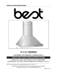
Range Hood
Use & Care Guide
Installation Manual
31130 (30” wide - Stainless)
31133 (36” wide - Stainless)
ENGLISH
Models
HB0108
09030 rev. A
SEARS CANADA INC., Toronto, Ontario M5B 2B8
www.sears.ca
READ AND SAVE THESE INSTRUCTIONS
TABLE OF CONTENTS
SECTION.................................................................. PAGE(S)
Warranty ................................................................................2
Safety Instructions .................................................................2
Operation ...............................................................................3
Cleaning ................................................................................3
Parts Included With Hood ......................................................4
Parts Not Included With Hood ...............................................4
Tools Needed ........................................................................4
Range Hood System .............................................................5
Equivalent Duct Length Chart................................................6
Select Installation Type .........................................................7
Wiring Installation ..................................................................8
Prepare the Hood ............................................................9-10
Install the Hood...............................................................11-12
Finalize the Installation ...................................................12-13
Installing Grease Filters .......................................................13
Changing Light Bulbs ..........................................................13
Service Parts .......................................................................14
WARRANTY
Full One Year Warranty Including Parts and Labour
For one year from the date of purchase, when the range hood is installed and operated
in Canada, in accordance with the instruction in the Owners Manual and Installation
Instructions, Sears Canada Inc. (‘‘Sears’’) will repair, or replace at its option, mechanical
or electrical parts, if defective in material and workmanship, and perform any necessary
adjustments at no charge.
NORMAL RESPONSIBILITY OF THE CONSUMERS
The following are not covered by this warranty:
1. Parts and service resulting from damage caused by accident, negligence or commercial
usage.
2. Parts and service required as a result of defective or inadequate fusing or house wiring.
3. Parts and service required as a result of fire, flood or Acts of God.
SEARS CANADA INC. TORONTO, ONTARIO M5B 2B8 1-800-4MY-HOME
SEARS MAINTENANCE AGREEMENT
Sears Maintenance Agreement... your way to buy tomorrow’s services at today’s prices...
and Sears Service is nationwide.
Maintain the value of your Kenmore range hood with a Sears Maintenance Agreement.
Sears range hoods as designed, manufactures and tested for years of dependable
operation. Yet, any modern appliance may require service from time to time.
Sears maintenance Agreement
Eliminates large or small repair bills resulting from normal use.
Allows for as many service calls as required.
Provides for service by professionnal Sears-Trained Technicians.
This Maintenance Agreement does not cover original installation, reinstallation or damage
resulting from external causes such as acts of abuse, theft, fire, flood, wind, lightning,
freezing, power failure, power reduction, etc.
SEARS CANADA INC.
222 Jarvis Street, Toronto, Ontario, Canada M5B 2B8
1-800-4MY-HOME
SAFETY INSTRUCTIONS
WARNING
! INTENDED FOR DOMESTIC COOKING ONLY !
WARNING
TO REDUCE THE RISK OF FIRE, ELECTRIC SHOCK, OR
INJURY TO PERSONS, OBSERVE THE FOLLOWING:
1. Use this unit only in the manner intended by the manufacturer. If
you have questions, contact the manufacturer at the address
listed in the warranty.
2. Before servicing or cleaning unit, switch power off at service
panel and lock the service disconnecting means to prevent
power from being switched on accidentally. When the service
disconnecting means cannot be locked, securely fasten a
prominent warning device, such as a tag, to the service panel.
3. Installation work and electrical wiring must be done by
qualified personnel in accordance with all applicable codes
and standards, including fire-rated codes and standards.
4. Sufficient air is needed for proper combustion and exhausting
of gases through the flue (chimney) of fuel burning equipment
to prevent backdrafting. Follow the heating equipment
manufacturer’s guideline and safety standards such as those
published by the National Fire Protection Association (NFPA), and
the American Society for Heating, Refrigeration and Air Conditioning
Engineers (ASHRAE), and the local code authorities.
5. When cutting or drilling into wall or ceiling, do not damage
electrical wiring and other hidden utilities.
6. Do not use this range hood with any additional solid state speed
control device.
7. Ducted fans must always be vented to the outdoors.
8. To reduce the risk of fire, use only metal ductwork.
9. When performing installation, servicing or cleaning the unit, it
is recommended to wear safety glasses and gloves.
10. This unit must be grounded. To provide protection against
electric shock, connect to properly grounded outlets only.
11. Inspect ducting at least every 12 months or after every range
top fire in order to detect any risky conditions.
12. When applicable local regulations comprise more restrictive
installation and/or certification requirements, the aformentioned
requirements prevail on those of this document and the installer
agrees to conform to these at his own expenses.
TO REDUCE THE RISK OF A RANGE TOP GREASE FIRE:
1. Never leave surface units unattended at high settings. Boilovers
cause smoking and greasy spillovers that may ignite. Heat oils
slowly on low or medium settings.
2. Always turn hood ON when cooking at high heat or when
flambeing food (i.e.: Crêpes Suzette, Cherries Jubilee,
Peppercorn Beef Flambé).
3. Clean ventilating fan frequently. Grease should not be allowed
to accumulate on fan or filters.
4. Use proper pan size. Always use cookware appropriate for the
size of the surface element.
2
TO REDUCE THE RISK OF INJURY TO PERSONS IN THE
EVENT OF A RANGE TOP GREASE FIRE, OBSERVE THE
FOLLOWING:
1. SMOTHER FLAMES with a close-fitting lid, cookie sheet,
or metal tray, then turn off the burner. BE CAREFUL TO
PREVENT BURNS. If the flames do not go out immediately,
EVACUATE AND CALL THE FIRE DEPARTMENT.
2. NEVER PICK UP A FLAMING PAN - You may be burned.
3. DO NOT USE WATER, including wet dishcloths or towels - This
could cause a violent steam explosion.
4. Use an extinguisher ONLY if:
A. You know you have a Class ABC extinguisher and you
already know how to operate it.
B. The fire is small and contained in the area where it started.
C. The fire department is being called.
D. You can fight the fire with your back to an exit.
*Based on “Kitchen Fire Safety Tips” published by NFPA.
CAUTION !
1. For indoor use only.
2. For general ventilating use only. Do not use to exhaust
hazardous or explosive materials and vapors.
3. To avoid motor bearing damage and noisy and/or unbalanced
impellers, keep drywall spray, construction dust, etc. off power unit.
4. Your hood motor has a thermal overload which will automatically
shut off the motor if it becomes overheated. The motor will
restart when it cools down. If the motor continues to shut off
and restart, have the hood serviced.
5. For best capture of cooking impurities, the bottom of the hood
should be a minimum of 24” and a maximum of 30” above the
cooking surface.
6. Two installers are recommended because of the large size and
weight of this hood.
7. To reduce the risk of fire and to properly exhaust air on a ducted
installation, be sure to duct air outside. Do not exhaust air into spaces
within walls or ceiling or into attics, crawl spaces, or garage.
8. This product is equipped with a thermostat which may start
blower automatically. To reduce the risk of injury and to prevent
power from being switch on accidentally, switch power off at
service panel and lock or tag service panel.
9. Because of the high exhausting capacity of this hood, you
should make sure enough air is entering the house to replace
exhausted air. Open a window close to or in the kitchen.
10. To reduce the risk of fire and electric shock, the Kenmore Elite
hood should only be installed with its own built-in blower.
11. Please read specification label on product for further information
and requirements.
OPERATION
Always turn ON your hood before you begin cooking in order
to establish an air flow in the kitchen. Let the blower run for a
few minutes to clear the air after you turn off the range. This
will help keep the whole kitchen cleaner and brighter.
Nigthlight switch
Press this switch once to turn on the nightlight. Press this switch
once more to shut off the nightlight.
Warranty
OPERATION
CLEANING
HC0027
1
2
3
4
5
Installation
WARNING: The HEAT SENTRY thermostat can
start the blower even if the hood is turned OFF.
When this occurs, press the speed 3 switch
until its light indicator stops flashing if you
must stop the blower.
Cleaning
ON/OFF Blower speed switches
Press the switch corresponding to the desired blower speed.
The light over the switch indicates the selected speed (from 1
for low speed to 4 for high speed). To turn off the blower, press
once more on the corresponding blower speed switch.
HEAT SENTRY™
Your hood is equipped with a HEAT SENTRY thermostat. This
thermostat is a device that will turn on or speed up the blower if
it senses excessive heat above the cooking surface. The light
indicator over speed 3 switch will quickly flash.
1) If blower is OFF - it turns blower ON to speed 3.
2) If blower is ON at a lower (or higher) speed setting - it turns
blower to speed 3.
When the temperature level drops to normal, the blower will
return to its original setting and the light indicator over speed 3
switch will stop flashing.
Hood Cleaning
Stainless steel cleaning: How to maintain its “BRIGHT LOOK”
Do:
- Regularly wash surfaces with clean cloth or rag soaked with
warm water and mild soap or liquid dish detergent.
- Always clean in the direction of original polish lines.
- Always rinse well with clear water (2 or 3 times) after cleaning.
Wipe dry completely.
- You may also use a specialized household stainless steel
cleaner.
Don’t:
- Do not use any steel or stainless steel wool or any other
scrapers to remove stubborn dirt.
- Do not use any harsh or abrasive cleaners.
- Do not allow dirt to accumulate.
- Do not let plaster dust or any other construction residues
reach the hood. During construction/renovation, cover the
hood to make sure no dust sticks to stainless steel surface.
Avoid: when choosing a detergent
- Any cleaners that contains bleach will attack stainless
steel.
- Any products containing: chloride, fluoride, iodide, bromide
will deteriorate surfaces rapidly.
- Any combustible products used for cleaning such as
acetone, alcohol, ether, benzol, etc., are highly explosive
and should not be used close to a range.
Operation
Delay OFF switch
When a speed is selected, press the Delay OFF switch to
activate the delay function. The corresponding speed indicator
LED will start flashing to indicate this function is activated.
The fan will continue to operate for 5 minutes and will stop
automatically. To cancel the delay function, press the Delay
OFF switch once again; the blower will then work in normal
mode.
NOTE: The blower speed can be increased or decreased during
Delay mode without starting another 5-minute cycle.
Safety
1. Blower Delay switch
4. Filter maintenance indicator
2. ON/OFF Blower speed switches
5. Nightlight switch
3. Halogen lights switch
Grease filters
The grease filters should be cleaned frequently. Use a warm
detergent solution. Grease filters are dishwasher safe.
Wash more often if your cooking style generates greater grease
- like frying foods or wok cooking.
Remove filters by pulling latch tabs and rotating filters
downward.
Halogen lights switch
This switch provides 3 different lighting levels, according to
your needs. The lighting intensity changes by increments of 1
(i.e.: press once for low intensity, once again to get more, up
to three times). From the higher intensity, press once again to
shut off the lights.
Uses 120 Volts, 50 W, MR 16 with GU10 base or PAR 16 with
GU10 base, shielded halogen bulbs (included).
Service Parts
WARNING: In order to prevent the risk of
personal injury, do not install a lamp identified
for use only in enclosed fixtures.
Filter maintenance indicator
After 24 hours of operation, the filter maintenance light indicator
will start blinking. This indicates the filters need to be cleaned
in order to maintain efficient operation of the unit. The indicator
light will blink until the function is reset by pressing the nightlight
switch for 3 seconds.
3
PARTS INCLUDED WITH HOOD
PARTS INCLUDED WITH HOOD
Aluminum grease filters
(2 per hood)
HR0010
HR0051
Parts Bag including:
5 no. 8 x 1½” countersunk screws
8 no. 8 x 3/4” screws
6 no. 8 x 3/8” screws
6 Drywall anchors
3 Washers
HR0012
120 V, 50 W, PAR 16 with GU10 base
shielded halogen lamp
(2 per hood)
Sears Part No. V05921
Decorative flue assembly
(lower and upper flues)
3¼” x 10” adapter/damper
(for horizontal discharge)
HR0011
HR0044
8” round adapter/damper
(for vertical discharge), in a
separate box
HR0041
PARTS NOT INCLUDED WITH HOOD
Hood mounting bracket
HR0042
Upper flue mounting bracket
Ducting Accessories
(See “Range Hood System” on page 5 for Ducting Accessory
Model Nos.)
Optional flue extension for 10-ft. ceilings (model no. 31131)
HR0043
TOOLS NEEDED FOR HOOD INSTALLATION
Screwdriver
(Robertson or Phillips)
Drill
Tape
Measure
Pencil
Sabre
Keyhole
Saw -or- Saw
4
Wire
Stripper
Duct Tape
RANGE HOOD SYSTEM
Broan Model
634 or 644
Roof Cap
Broan Model 643
8” Round Wall Cap
Warranty
Broan Model 639
3¼” x 10”
Standard Wall Cap
Wall & Roof Caps
Elbow
Safety
8” Round
Adjustable Elbow
Upper
Decorative
Flue
Operation
Broan Model 401
Standard
3¼” x 10” Duct
Ductwork
8” Round
Standard Duct
Adapter/damper
8” round (supplied
with hood)
For vertical discharge
Lower
Decorative
Flue
Adapter/dampers
Cleaning
Adapter/damper
3¼” x 10” (supplied
with hood)
For horizontal discharge
31130 or 31133
Range Hood
Installation
Single Blower
(supplied with hood)
5
Service Parts
HL0142
EQUIVALENT DUCT LENGTH CHART
Kenmore range hoods are designed to perform efficiently when attached to long runs of duct. As a point of reference, this hood
will function at approximately 80% of its rated air performance when 300 equivalent feet of 8” round ductwork is attached. Use
this chart to calculate the equivalent duct length of your system. Note that 8” round is the minimum recommended duct size.
HR0047
Straight Duct
8-in. round x 2-ft. long
Equivalent length
HR0048
Broan Model 643
8-in. Round Wall Cap
Equivalent length
2 ft.
30 ft.
(15-ft. w/o damper)
HR0045
Broan Model 401
Straight Duct
3¼” x 10” x 1 ft. long
Equivalent length
4 ft.
HR0049
Broan Model 634 or 644
8-in. Round Roof Cap
Equivalent length
30 ft. (7-ft. w/o damper)
HR0046
8-in. Round Elbow
Equivalent length
10 ft.
HR0050
Broan Model 639
3¼” x 10” Wall Cap
Equivalent length
90 ft.
(14-ft. w/o damper)
6
SELECT INSTALLATION TYPE
Warranty
1. Plan where and how the ductwork will be installed.
Install proper-sized ductwork, transition(s), elbow(s), and
roof or wall cap.
For best results, use a minimum number of transition and
elbows.
2. The minimum hood distance above cooktop must not be
less than 24’’. A maximum of 30’’ above cooktop is highly
recommended for best capture of cooking impurities.
Distances over 30” are at the installer and users discretion;
providing that ceiling height and decorative flue length
permit.
ROOF CAP
8” ROUND DUCT
DECORATIVE
FLUE
WALL
HOOD
CAP
There are 2 different heights for the horizontal ductwork.
Refer to page 8 for more details.
Safety
NOTE
3¼” X 10”
DUCT
REFER TO CHART
MINIMUM HOOD DISTANCE ABOVE COOKTOP
8 FEET
24”
9 FEET
29½”
10 FEET
25”
FOR DISTANCE ABOVE
COOKING SURFACE
HH0134A
Operation
CEILING
HEIGHT
*10-ft. ceilings require flue extension model no. 31131
(sold separately).
Refer to illustrations below to locate duct opening according to discharge type chosen (grey parts to be installed later).
VERTICAL DISCHARGE
HORIZONTAL DISCHARGE
CL
CL
1415⁄16”
1715⁄16”
25⁄16”
43⁄16”
8” DIA.
33⁄16”
OR
HK0122A
30” WIDTH HOOD
36” WIDTH HOOD
12¾”
9¾”
1415⁄16”
1715⁄16”
Installation
HK0117A
81⁄16”
Cleaning
30” WIDTH HOOD
36” WIDTH HOOD
Service Parts
7
WIRING INSTALLATION
WARNING: Improper grounding can result in a risk of electric shock. Consult a qualified electrician
if the grounding instructions are not completely understood, or if doubt exists as to whether the
appliance is properly grounded. Do not use an extension cord. If the power supply cord is too short,
have a qualified electrician install an outlet near the appliance, in accordance with all applicable codes
and standards. Turn off electrical power at service entrance before wiring.
GROUNDING INSTRUCTIONS
This appliance must be grounded. In the event of an electrical short circuit, grounding reduces the risk of electric shock by providing
an escape wire for the electric current. This appliance is equipped with a cord having a grounding wire with a grounding plug.
The plug must be plugged into an outlet that is properly installed and grounded.
Position the outlet within the space covered by the decorative
flue. Place the outlet at a maximum distance of 24” (from where
the cord exits from the hood). The center of the outlet must be
positioned at 2¾” from the center of the future hood location
(as illustrated beside). Make sure this does not interfere with
a mounting bracket fastening area or with the decorative flue
(where the flue touches the wall).
HE0106A
!
CAUTION: The BLUE wires are for a make-up
air device option (not available in Canada). Never
remove the caps on the BLUE wires end.
HE0107
8
PREPARE THE HOOD
Warranty
1. Lay the hood on its back on a table.
Remove grease filters by lifting the metal latch tab (1),
pushing down on the filter (2) and tilting is towards you (3).
3
1
NOTE
Safety
Use a piece of cardboard to avoid damaging the table or the
hood.
2
HD0376
2. Choose the opening:
VERTICAL DISCHARGE:
Using a Robertson or a Phillips no. 2 screwdriver, remove
the 4 top metal plate retaining screws in order to clear the
vertical discharge opening (see illustration beside). Discard
the metal plate and its screws.
Operation
RETAINING SCREWS LOCATIONS
HO0142
Cleaning
1
2
HORIZONTAL DISCHARGE:
In order to ease a retrofit installation, the horizontal discharge
may be positioned on higher OR on lower back of the hood.
From outside the unit, remove the knockout for the chosen
discharge opening (see illustrations beside).
OR
Installation
HR0038
OR
Service Parts
9
PREPARE THE HOOD
NOTE
The following instructions are for the horizontal installation only. For a vertical installation, go to the “Install the hood” section on
page 11.
These Kenmore Elite Series range hoods are factory shipped with the blower mounted for a vertical discharge configuration. For
a horizontal discharge configuration, disassemble the blower from the inner top of the hood (see illustrations below). It will be
assembled to the inner back of the hood once the hood is mounted on the wall.
3. Uplug the blower.
HE0085
RIGHT SIDE
LEFT SIDE MOUNTING
MOUNTING SCREW
SCREW LOCATION
LOCATION
4. Using a 5/16” socket, or a Robertson or a Phillips no. 2
screwdriver, remove all blower mounting screws from
the inner top of the hood. Set aside the blower and its
screws.
HD0386
HD0385
NOTE
If this hood replaces another one, please note that the location of the air exhaust can vary from one manufacturer to another. In
order to ease a retrofit installation, the horizontal discharge may be positioned on higher OR on lower back of the hood.
1
2
5. According to your needs, the adapter/damper can
be installed to the higer or lower back discharge
using the upper screw holes on each side of the
adapter/damper. See illustrations beside.
HJ0040
6. Secure the adapter/damper to the back of the hood using 2 no. 8 x 3/8” screws (included). Seal the adapter/damper to the
hood using metal foil duct tape.
NOTE
The wall ducting must be properly prepared to receive the adapter. Before performing the installation, make sure the adapter
fits easily in the duct.
10
INSTALL THE HOOD
Warranty
WARNING: When cutting or drilling into wall,
do not damage electrical wiring and other
hidden utilities.
HD0374A
36¾” = BOTTOM OF HOOD 24” ABOVE COOKTOP
42¾” = BOTTOM OF HOOD 30” ABOVE COOKTOP
2. Center the upper flue mounting bracket with the center line
previously drawn and place it flush with the ceiling.
Use the upper flue mounting bracket as a template to mark
the position of its screws.
Drill the 3 screw holes using a 3/16” drill bit.
Insert the included drywall anchors into the drilled holes
(1 per hole).
Secure the upper flue bracket to the wall using 3 no. 8 x 3/4”
screws.
Ensure that the bracket is tight against the wall.
CEILING
CL
HD0377
SCREW LOCATIONS
MOUNTING BRACKET
FLUSH WITH CEILING
Operation
WARNING: BE CAREFUL when installing the decorative flue and hood, they may have sharp edges.
CAUTION: DO NOT REMOVE the protective plastic film covering the decorative flue (upper & lower).
3. Align the hood and center it above the hood mounting
bracket. Gently lower the hood until it securely engages the
bracket.
Level the hood.
With the hood hanging in place, secure it to the wall through
both holes located in the inside upper back of hood using
2 no. 8 x 1½” screws.
Drill through both holes located in the inside lower back
of hood using a 3/16” drill bit. Insert the included drywall
anchors into the drilled holes (one for each hole). Secure
the hood to the wall using 2 no. 8 x 3/4” screws and
2 washers.
UPPER HOLES LOCATION
BACK OF THE HOOD
SIDE VIEW
B
A
NOTE
RIGHT SIDE
In order to ease installation, before mounting the blower,
prepare the screw holes by screwing all 4 screws without
the blower, then remove and mount the blower.
5. Plug the blower back in and plug hood power cord into the
outlet.
MOUNTING
SCREW
LOCATION
HD0387
11
Ø 3/16” TYP.
Service Parts
4. Position the blower on the higher (A) or lower (B) back wall
discharge as determined previously.
Using a 5/16” socket, or a Robertson or a Phillips no. 2
screwdriver and the 4 previously removed screws, secure
the blower to the hood.
LOWER HOLES LOCATION
Installation
HD0380A
HORIZONTAL DISCHARGE ONLY:
Cleaning
!
!
Safety
1. Construct wood wall framing that is flush with surface of wall
studs.
Wood wall framing must be at least 1/2” thick and 3” high.
Ensure to assemble wood wall framing to wall studs for a
solid installation.
Ensure the height of the framing will allow the mounting
bracket to be secured to the framing within the dimensions
shown (see illustration beside).
After wall surface is finished, carefully center and level the
hood mounting bracket over installation location. Secure it
to wall framing using 3 no. 8 x 1½” screws.
Using a level, draw a vertical line up to the ceiling starting
from the mounting bracket center.
INSTALL THE HOOD
INSTALL THE HOOD
VERTICAL DISCHARGE ONLY:
VERTICAL DISCHARGE ONLY:
6. Mount the 8” round adapter/damper (included in a separate
box) to the hood using 4 no. 8 x 3/8” sheet metal screws
(included).
7. Plug hood power cord into the outlet.
Slide a 8” metal round duct over the adapter/damper. Use
metal foil duct tape to seal the joint.
HJ0037
HJ0041
FINALIZE THE INSTALLATION
UPPER FLUE
TOP CORNERS
1. Remove protective plastic film covering the lower flue
only.
Peel off both corners at the top of the upper flue.
Position the lower flue rear notches down (the ones with the
45° angle).
Gently slide upper flue inside lower flue, louvers end first
(so that louvers are hidden inside lower flue, as they are not
needed).
LOUVERS
NOTE
Both lower and upper flues are included with the hood, but
for a 10 foot ceiling, discard the provided upper flue and
use the optional extension flue, part no. 31131 (purchase
separately).
LOWER FLUE
REAR NOTCH
HO0144
LOWER FLUE
REAR NOTCH
2. Carefully slide in place decorative flue base (notches end
first) between the shaded part and the exterior wall of the
top of the hood.
HO0143
12
FINALIZE THE INSTALLATION
3. Slide up the upper flue until it is aligned with its mounting
bracket. The bracket must be inside the flue. Secure
the upper flue to its bracket using 2 no. 8 x 3/8” screws
(included). See illustration beside.
Warranty
UPPER FLUE MOUNTING BRACKET
FRONT VIEW
UPPER
NOTE
FLUE
Duct not shown in illustration to ease understanding.
Safety
4. Remove protective plastic film covering the upper flue.
HO0140
INSTALLING GREASE FILTERS
Operation
Rest rear filters edge on filter springs (A) in the range hood.
Using metal latch tab, tilt up the filters into position. Make sure
filter tabs (B) are securely engaged in range hood front edge
after installation.
A
HD0393
B
Cleaning
CHANGING LIGHT BULBS
!
WARNING: In order to prevent the risk of personal injury, do not install a lamp identified for use only in enclosed
fixtures.
This range hood must use 2 shielded halogen lamps (120 V, 50 W PAR16 with GU10 base), included.
Refer to page 4 for ordering information.
WARNING: In order to prevent the risk of personal injury, the halogen lamps must cool down before removing
them.
1. To remove lamps, gently push upwards and turn
counterclockwise to disengage bulb leads from their
grooves.
1
2
3
Installation
!
NOTE
If need be, use a rubber dishwashing glove to add grip when
removing the bulb.
HO0089
13
Service Parts
2. Install the new lamps by placing the bulb leads into their
grooves in the socket.
3. Gently push upwards and turn clockwise until secure.
SERVICE PARTS
1
2
3
PART NO.
DESCRIPTION
30”
36”
1
18504
UPPER FLUE MOUNTING BRACKET
1
1
2
18494
UPPER DECORATIVE FLUE
1
1
3
18496
LOWER DECORATIVE FLUE
1
1
4
18515
1
1
5
18522
1
1
16
5
15
7
12
8
9
13
10
11
14
TOP EXHAUST
ELECTRONIC CONTROL MODULE
(INCLUDING OVERLAY, ITEM 6)
6
07322
OVERLAY
1
1
05917
SOCKET (GU10)
2
2
8
16154
SOCKET HOLDER (LEFT
AND RIGHT GU10 PLASTIC)
2
2
9
16172
LIGHT TRIM (PLASTIC PAINTED
GREY FOR GU10)
2
2
10
05921
SHIELDED HALOGEN LAMP
(120 V, 50 W, GU10)
2
2
11
09022
TRANSFORMER
1
1
12
08582
INTERNAL BLOWER
(INCLUDING CAPACITOR)
1
1
13
08783
CAPACITOR
1
1
14
18523
MICROMESH FILTERS
13.83” X 13.83” (SET OF 2)
1
1
15
09035
KENMORE ELITE LOGO
1
1
16
09014
HOOD MOUNTING BRACKET
1
1
17
08543
8” ROUND A DAPTER/DAMPER
1
1
18
13296
3¼” X 10” ADAPTER/DAMPER
1
1
*
09030
KENMORE ELITE
INSTALLATION GUIDE
1
1
09027
PARTS BAG: 5 NO. 8 X 1½”
COUNTERSUNK SCREWS,
8 NO. 8 X 3/4” SCREWS,
6 NO. 8 X 3/8” SCREWS,
6 DRYWALL ANCHORS,
3 WASHERS
1
1
17
4
COVER PLATE FOR 8” ROUND
7
18
6
QTY. (HOOD WIDTH)
KEY NO.
HL0143
*
ORDER REPLACEMENT PARTS BY PART NO. - NOT BY KEY NO.
*NOT ILLUSTRATED.