1
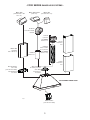
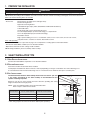
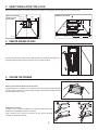
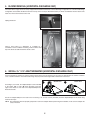
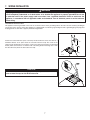
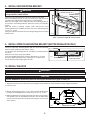
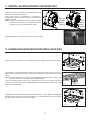
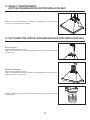
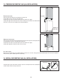
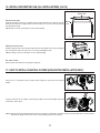
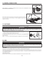
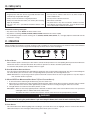
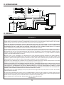
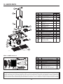
INSTALLATION INSTRUCTIONS HB0104 CC32I SERIES ! INTENDED FOR DOMESTIC COOKING ONLY ! READ AND SAVE THESE INSTRUCTIONS INSTALLER: LEAVE THIS MANUAL WITH HOMEOWNER. HOMEOWNER: USE AND CARE INFORMATION ON PAGES 13 AND 14. Venmar Ventilation ULC, 550 Lemire Blvd., Drummondville QC J2C 7W9 1-800-567-3855 REGISTER YOUR PRODUCT ONLINE AT: www.bnv.ca For additional information - visit www.venmar.ca 09023 rev. 05 ! WARNING ! TO REDUCE THE RISK OF FIRE, ELECTRIC SHOCK OR INJURY TO PERSONS, OBSERVE THE FOLLOWING: WARNING TO REDUCE THE RISK OF INJURY TO PERSONS IN THE EVENT OF A RANGE TOP GREASE FIRE, OBSERVE THE FOLLOWING*: 1. Use this unit only in the manner intended by the manufacturer. If you have questions, contact the manufacturer at the address or telephone number listed in the warranty. 1. SMOTHER FLAMES with a close-fitting lid, cookie sheet or metal tray, then turn off the burner. BE CAREFUL TO PREVENT BURNS. IF THE FLAMES DO NOT GO OUT IMMEDIATELY, EVACUATE AND CALL THE FIRE DEPARTMENT. 2. Before servicing or cleaning unit, switch power off at service panel and lock service disconnecting means to prevent power from being switched on accidentally. When the service disconnecting means cannot be locked, securely fasten a prominent warning device, such as a tag, to the service panel. 2. NEVER PICK UP A FLAMING PAN — You may be burned. 3. DO NOT USE WATER, including wet dishcloths or towels — This could cause a violent steam explosion. 3. Installation work and electrical wiring must be done by qualified personnel in accordance with all applicable codes and standards, including fire-rated construction codes and standards. 4. Use an extinguisher ONLY if: A. You own a Class ABC extinguisher and you know how to operate it. B. The fire is small and contained in the area where it started. 4. Sufficient air is needed for proper combustion and exhausting of gases through the flue (chimney) of fuel burning equipment to prevent backdrafting. Follow the heating equipment manufacturer’s guidelines and safety standards such as those published by the National Fire Protection Association (NFPA) and the American Society for Heating, Refrigeration and Air Conditioning Engineers (ASHRAE) and the local code authorities. C. The fire department has been called. D. You can fight the fire with your back to an exit. * Based on “Kitchen Fire Safety Tips” published by NFPA. CAUTION 1. For indoor use only. 5. When cutting or drilling into wall or ceiling, do not damage electrical wiring and other hidden utilities. 2. For general ventilating use only. Do not use to exhaust hazardous or explosive materials and vapors. 6. Ducted fans must always be vented to the outdoors. 3. To avoid motor bearing damage and noisy and/or unbalanced impellers, keep drywall spray, construction dust, etc. off power unit. 7. Do not use this unit with any solid-state speed control device. 8. To reduce the risk of fire, use only metal ductwork. 9. This unit must be grounded. 4. Your hood motor has a thermal overload which will automatically shut off the motor if it becomes overheated. The motor will restart when it cools down. If the motor continues to shut off and restart, have the hood serviced. 10. When applicable local regulations comprise more restrictive installation and/or certification requirements, the aforementioned requirements prevail on those of this document and the installer agrees to conform to these at his own expenses. 5. The minimum hood distance above cooktop must not be less than 24” (30” over a gas range) A maximum of 30” above cooktop is recommended for best capture of cooking impurities. TO REDUCE THE RISK OF A RANGE TOP GREASE FIRE: a) Never leave surface units unattended at high settings. Boilovers cause smoking and greasy spillovers that may ignite. Heat oils slowly on low or medium settings. 6. Two installers are recommended because of the large size and weight of this unit. 7. To reduce the risk of fire and to properly exhaust air, be sure to duct air outside — Do not exhaust air into spaces within walls or ceiling or into attics, crawl space or garage. b) Always turn power pack ON when cooking at high heat or when flambeing food (i.e.: Crêpes Suzette, Cherries Jubilee, Peppercorn Beef Flambé). 8. This product is equipped with a thermostat which may start blower automatically. To reduce the risk of injury and to prevent power from being switched on accidentally, switch power off at service panel and lock or tag service panel. c) Clean ventilating fans frequently. Grease should not be allowed to accumulate on fan, filters or in exhaust ducts. d) Use proper pan size. Always use cookware appropriate for the size of the surface element. 9. Because of the high exhausting capacity of this hood, you should make sure enough air is entering the house. Open a window close to or in the kitchen. 10. To reduce the risk of fire and electrical shock, the Venmar Connaisseur CC32I Series models should only be installed with their own built-in blowers. 11. Please read specification label on product for further information and requirements. 2 - CC32I SERIES RANGE HOOD SYSTEMS - MODEL 639 (STANDARD 3¼” X 10” WALL CAP) MODEL 634 OR 644 (ROOF CAP) MODEL 643 (8” ROUND WALL CAP) 8” ROUND ADJUSTABLE ELBOW, OPTIONAL PLENUM (SUPPLIED WITH 09025 NON-DUCT KIT UPPER DECORATIVE FLUE 8” ROUND METAL FLEXIBLE MODEL 401 (STANDARD 3¼” X 10” DUCT) DUCT (SUPPLIED WITH 8” ROUND 09025 NON-DUCT KIT) STANDARD DUCT LOWER DECORATIVE FLUE ADAPTER/DAMPER 3¼” X 10” (SUPPLIED WITH HOOD) FOR HORIZONTAL ADAPTER/DAMPER 8” ROUND (SUPPLIED WITH HOOD) FOR VERTICAL DISCHARGE DISCHARGE CC32I SERIES RANGE HOOD HL0137 SINGLE BLOWER (SUPPLIED WITH HOOD) 3 1. PREPARE THE INSTALLATION ! WARNING When performing installation, servicing or cleaning the unit, it is recommended to wear safety glasses and gloves. NOTE: Before proceeding to the installation, check the contents of the box. If items are missing or damaged, contact the manufacturer. Make sure that the following items are included: - Hood - Accessories • Decorative flue assembly (lower and upper flues) • Hood mounting bracket • Upper flue mounting bracket • 2 Shielded halogen lamps (120 V, 50 W, MR16 or PAR16 with GU10 base) • 2 Thin baffle filters • 2 Filter knobs with screws, taped inside the hood • 8” round adapter/damper (for vertical discharge), in a separate box • 3¼” x 10” adapter/damper (for horizontal discharge) • Installation manual • Bag of parts including: 5 no. 8 x 1½” countersunk screws, 8 no. 8 x 3/4” screws, 6 no. 8 x 3/8” screws, 6 drywall anchors, 3 washers. If need be, discard extra screws. Parts sold separately: - Duct, elbows, wall and roof caps. Refer to page 3 for a complete list of venting options and model numbers. - Non-duct kit model 09025, mandatory for non-ducted installation. - Optional flue extension for 10-ft. ceilings model no. 09019. NOTE: During installation, protect countertop and/or cooktop. 2. SELECT INSTALLATION TYPE 2.1 NON-DUCTED INSTALLATION Non-duct kit model 09025 is required for a non-ducted installation. 2.2 DUCTED INSTALLATION Plan where and how the ductwork will be installed. Install proper-sized ductwork, elbows and roof or wall cap depending on the type of installation. For vertical discharge, use 8” round ductwork and for horizontal discharge use 3¼” x 10” ductwork. Use metal foil duct tape to seal duct joints. 2.3 ALL INSTALLATIONS The minimum hood distance above cooktop must not be less than 24” (30” over a gas range). A maximum of 30” above cooktop is recommended for best capture of cooking impurities. ROOF CAP 8” ROUND DUCT Distances over 30” are at the installer and users discretion; providing that ceiling height and decorative flue length permit. NOTE: There are 2 different heights for the horizontal ductwork. Refer to steps 4 and 6 for more details. MINIMUM HOOD DISTANCE ABOVE MINIMUM HOOD DISTANCE ELECTRIC RANGE COOKTOP ABOVE GAS RANGE COOKTOP 8 FT. 24 IN. 30 IN. 9 FT. 29½ IN. 30 IN. CEILING HEIGHT 10 FT.* 25 IN. 30 IN. * 10-ft. ceilings require flue extension model no. 09019 (sold separately). 4 DECORATIVE FLUE HOOD WALL CAP 3¼” X 10” DUCT REFER TO CHART FOR DISTANCE ABOVE COOKING SURFACE HH0134A 2. SELECT INSTALLATION TYPE (CONT'D) Refer to illustrations below to locate duct opening according to discharge type chosen (grey parts to be installed later). CL VERTICAL DISCHARGE 30” WIDTH HOOD OR NON-DUCTED INSTALLATION 36” WIDTH HOOD HORIZONTAL DISCHARGE 1415⁄16” 1715⁄16” CL 25⁄16” 43⁄16” 8” DIA. 33⁄16” 12¾” 9¾” OR 30” WIDTH HOOD 36” WIDTH HOOD HK0117A 81⁄16” 1415⁄16” 1715⁄16” HK0122A 3. REMOVE GREASE FILTERS 2 Rest the range hood on a table. Remove tape on filters. Lift out filters from range hood by pushing them towards the back and rotate, then set aside the filters. 1 HD0391 4. CHOOSE THE OPENING RETAINING SCREW LOCATIONS VERTICAL DISCHARGE OR NON-DUCTED INSTALLATION: Using a Robertson or a Phillips no. 2 screwdriver, remove the 4 top metal plate retaining screws in order to clear the vertical discharge opening (see illustration beside). Discard the metal plate and its screws. HO0142 1 HORIZONTAL DISCHARGE: OR In order to ease a retrofit installation, the horizontal discharge may be positioned on higher OR lower back of the hood. From outside the unit, remove the knockout for the chosen discharge opening (see illustrations beside). HR0038 5 2 OR 5. BLOWER REMOVAL (HORIZONTAL DISCHARGE ONLY) The CC32I Series range hoods are factory shipped with the blower mounted for a vertical discharge configuration. For a horizontal discharge configuration, disassemble the blower from the inner top of the hood (see illustrations below). It will be assembled to the inner back of the hood once the hood is mounted on the wall. Unplug the blower. HE0085 LEFT SIDE MOUNTING RIGHT SIDE MOUNTING SCREW LOCATIONS SCREW LOCATIONS Using a 5/16” socket, or a Robertson or a Phillips no. 2 screwdriver, remove all blower mounting screws from the inner top of the hood. Set aside the blower and its screws. HD0385 HD0386 6. INSTALL 3¼” X 10” ADAPTER/DAMPER (HORIZONTAL DISCHARGE ONLY) If this hood replaces another one, please note that the location of the air exhaust can vary from one manufacturer to another. In order to ease a retrofit installation, the horizontal discharge may be positioned on higher OR on lower back of the hood. 1 HIGHER BACK 2 LOWER BACK According to your needs, the adapter/damper can be installed to the higher () or lower () back discharge using the upper screw holes on each side of the adapter/damper. See illustration beside. HJ0040 Secure the adapter/damper to the back of the hood using 2 no. 8 x 3/8” screws (included). Seal the adapter/damper to the hood using metal foil duct tape. NOTE: The wall ducting must be properly prepared to receive the adapter. Before performing the installation, make sure the adapter fits easily in the duct. 6 7. WIRING INSTALLATION ! WARNING Improper grounding can result in a risk of electric shock. Consult a qualified electrician if the grounding instructions are not completely understood, or if doubt exists as to whether the appliance is properly grounded. Do not use an extension cord. If the power supply cord is too short, have a qualified electrician install an outlet near the appliance, in accordance with all applicable codes and standards. Turn off electrical power at service entrance before wiring. GROUNDING INSTRUCTIONS This appliance must be grounded. In the event of an electrical short circuit, grounding reduces the risk of electric shock by providing an escape wire for the electric current. This appliance is equipped with a cord having a grounding wire with a grounding plug. The plug must be plugged into an outlet that is properly installed and grounded. Position the outlet within the space covered by the decorative flue. Place the outlet at a maximum distance of 24” (from where the cord exits from the hood). The center of the outlet must be positioned at 2¾” from the center of the future hood location (as illustrated beside). Make sure this does not interfere with a mounting bracket fastening area or with the decorative flue (where the flue touches the wall). HE0106A CAUTION The BLUE wires are for a make-up air device option (not available in Canada). Never remove the caps on the BLUE wires end. HE0107 7 8. INSTALL HOOD MOUNTING BRACKET ! WARNING WALL STUDS When cutting or drilling into wall, do not damage electrical wiring and other hidden utilities. Construct wood wall framing that is flush with surface of wall studs. Wood wall framing must be at least 1/2” thick and 3” high. Ensure to assemble wood wall framing to wall studs for a solid installation. Make sure the height of the framing will allow the mounting bracket to be secured to the framing within the dimensions shown (see illustration beside). After wall surface is finished, carefully center and level the hood mounting bracket over installation location. Secure it to wall framing using 3 no. 8 x 1½” screws. Using a level, draw a vertical line up to the ceiling starting from the mounting bracket center. FRAMING BEHIND DRYWALL HD0374A 36¾” = BOTTOM OF HOOD 24” ABOVE COOKTOP 42¾” = BOTTOM OF HOOD 30” ABOVE COOKTOP 9. INSTALL UPPER FLUE MOUNTING BRACKET (DUCTED INSTALLATION ONLY) Center the upper flue mounting bracket with the center line previously drawn in step 9 and place it flush with the ceiling. Use the upper flue mounting bracket as a template to mark the position of its screws. Drill the 3 screw holes using a 3/16” drill bit. Insert the included drywall anchors into the drilled holes (1 per hole). Secure the upper flue bracket to the wall using 3 no. 8 x 3/4” screws. Ensure that the bracket is tight against the wall. CEILING CL HD0377 SCREW LOCATIONS MOUNTING BRACKET FLUSH WITH CEILING 10. INSTALL THE HOOD ! WARNING BE CAREFUL when installing the decorative flue and hood, they may have sharp edges. CAUTION DO NOT REMOVE the protective plastic film covering the decorative flue (upper & lower) yet. 1. Align the hood and center it above the hood mounting bracket. Gently lower the hood until it securely engages the bracket. 2. Level the hood. UPPER HOLES LOCATION 3. With the hood hanging in place, secure it to the wall through both holes located in the inside upper back of hood using 2 no. 8 x 1½” screws. 4. Drill through both holes located in the inside lower back of hood using a 3/16” drill bit. Insert the included drywall anchors into the drilled holes (one for each hole). Secure the hood to the wall using 2 no. 8 x 3/4” screws and 2 washers. BACK OF THE HOOD SIDE VIEW HD0380A 8 LOWER HOLES LOCATION Ø 3/16” TYP. 11. REINSTALL BLOWER (HORIZONTAL DISCHARGE ONLY) A Position the blower on the higher (A) or lower (B) back wall discharge as determined previously. Using a 5/16” socket, or a Robertson or a Phillips no. 2 screwdriver and the 4 previously removed screws, secure the blower to the hood. NOTE: In order to ease installation, before mounting the blower, prepare the screw holes by screwing all 4 screws without the blower, then remove and mount the blower. B RIGHT SIDE MOUNTING RIGHT SIDE SCREW MOUNTING LOCATIONS SCREW LOCATIONS HD0387 Plug the blower back in and plug hood power cord into the outlet. HE0085 12. PLENUM INSTALLATION (NON-DUCTED INSTALLATION ONLY) Using 4 no. 8 x 3/8” provided screws, assemble the 8” round adapter to the lower plenum plate. HA0077 Carefully align the upper plenum plate central notch with the line traced in step 9 (see inset at right) and place it flush to the ceiling. Use the plate as a template to mark the position (A) of its screws. NOTE: To ease installation, there are many screw configurations: 6 in ceiling and 2 in wall, on each side. Only 4 screws are needed to hold the top plenum plate. Insert the included drywall anchors in the marked holes, then secure the upper plate using 4 no. 8 x 3/4” screws and washers (included with 09025 non-duct kit). Make sure the plate is tight against the wall and ceiling. A A HD0382 Assemble the lower plenum plate and transition assembly to the upper plate by inserting both tabs of the top plenum plate to their corresponding slots in lower plenum plate. Secure the plenum assemby using 2 no. 8-18 x 3/8” screws (included). HD0388 9 13. INSTALL 8” ADAPTER/DAMPER (VERTICAL DISCHARGE AND NON-DUCTED INSTALLATION ONLY) Mount the 8” round adapter/damper (included in a separate box) to the hood using 4 no. 8 x 3/8” sheet metal screws (included). HJ0038 14. DUCT CONNECTION (VERTICAL DISCHARGE AND NON-DUCTED INSTALLATION ONLY) VERTICAL DISCHAGE: Plug hood power cord into the outlet. Slide a 8” metal round duct over the adapter/damper on the hood. Use metal foil duct tape to seal the joint. HJ0037 NON-DUCTED INSTALLATION: Plug hood power cord into the outlet. Slide a 8” round flexible metal duct (included) over the adapter/damper on the hood. Use metal foil duct tape to seal the joint. HJ0043 Stretch the flexible metal duct up to the plenum, over the adapter. Use metal foil duct tape to seal the joint. HJ0044 10 15. PREPARE DECORATIVE FLUE (ALL INSTALLATIONS) DUCTED INSTALLATION: LOUVERS Remove protective plastic film covering the lower flue only. Peel off both corners at the top of the upper flue. Position the lower flue rear notches down (the ones with the 45° angle). Gently slide upper flue inside lower flue, louvers end first (so that louvers are hidden inside lower flue, as they are not needed for the ducted installation). LOWER FLUE REAR NOTCH HO0144 LOUVERS NON-DUCTED INSTALLATION: Remove protective plastic film covering the lower flue only, then just peel off the plastic film covering both top corners of the upper decorative flue. Position the lower flue rear notches down (the ones with the 45° angle). Gently slide upper flue inside lower flue, louvers end up. HA0078 ALL INSTALLATIONS: Both lower and upper flues are included with the hood, but for a 10 foot ceiling, discard the provided upper flue and use the optional extension flue, part no. 09019 (purchase separately). 16. INSTALL DECORATIVE FLUE (ALL INSTALLATIONS) LOWER FLUE REAR NOTCH Carefully slide in place decorative flue base (notches end first) between the shaded part and the exterior wall of the top of the hood. HO0143 11 16. INSTALL DECORATIVE FLUE (ALL INSTALLATIONS) (CONT'D) UPPER FLUE MOUNTING BRACKET FRONT VIEW DUCTED INSTALLATION: Slide up the upper flue until it is aligned with its mounting bracket. The bracket must be UPPER inside the flue. Secure the upper flue to its bracket using 2 no. 8 x 3/8” screws (included). FLUE See illustration beside. NOTE: Duct not shown in illustration to ease understanding. HO0140 NON-DUCTED INSTALLATION: Slide the upper flue up to the ceiling. The plenum must be inside the flue. Secure the upper flue to the plenum sides using 2 no. 8 x 1/4” screws (included) per side. NOTE: Ceiling not shown in illustration to ease understanding. HA0079 ALL INSTALLATIONS: Remove protective plastic film covering the upper flue. 17. HOW TO INSTALL CHARCOAL FILTERS (NON-DUCTED INSTALLATION ONLY) Using no. 6 x 1/2” provided screws, install one filter support on each side of the internal blower. HA0080 Position each filter over its support, insert both pins (A) into the round slot (B) on filter side and rotate to lock in place. B A HA0081 NOTE: Replacement is recommended after 25 hours of cooking or six months of operation. Purchase charcoal filter kit no. 18524 (2 round filters per kit). Replace more often if your cooking habits generates more grease. 12 18. REINSTALL GREASE FILTERS Using a Phillips no. 2 screwdriver, assemble the knob to each filter. The screw MUST BE on same end than filter tabs. See illustration beside. HO0139 Rest rear filters edge on filter springs in the range hood. Using knob, tilt up the filters into position. Make sure filter tabs (A) are securely engaged in range hood front edge after installation. HD0392 A 19. LIGHT BULBS This hood requires shielded halogen lamps (120 V, 50 W, PAR16 with GU10 base), included. ! WARNING Do not touch lamps during or soon after operation. Burns may occur. In order to prevent the risk of personal injury, only install shielded halogen lamps. Also, never install a cool beam, a dichroic lamp, a lamp not suitable for use in recessed luminaires or identified for use in enclosed fixtures. 1 1. Install the lamps by placing the bulb leads into their grooves in the socket. 2. Gently push upwards and turn clockwise until secure. To remove lamps, gently push upwards and turn counterclockwise to disengage bulb leads from their grooves. NOTE: If need be, use a rubber dishwashing glove to add grip when removing the bulb. 2 HO0090 20. CARE ! WARNING Before servicing or cleaning the unit, switch power off at service panel and lock service panel to prevent power from being switched on accidentally. When the service disconnecting means cannot be locked, securely fasten a prominent warning device, such as a tag, to the service panel. Grease Filters Grease filters should be cleaned monthly. Remove each grease filter by pushing it towards the back of the hood, then tilt the filter downward and remove. Use a warm detergent solution to clean the filters. Let them dry and reinstall them. Grease filters are dishwasher safe. Clean all-metal filters in the dishwasher using a non-phosphate detergent. Discoloration of the filter may occur if using phosphate detergent or as a result of local water conditions — but this will not affect filter performance. This discoloration is not covered by the warranty. Interior Blower Cleaning Remove the filters in order to access the blower. Vacuum blower to clean. Do not immerse in water. 13 20. CARE (CONT'D) Hood cleaning Do: Don’t: • Regularly wash with clean cloth or rag soaked with warm water and mild soap or liquid dish detergent. • Use any steel or stainless steel wool or any other scrapers to remove stubborn dirt. • Always clean in the direction of original polish lines. • Use any harsh or abrasive cleansers. • Always rinse well with clear water (2 or 3 times) after cleaning. Wipe dry completely. • Allow dirt to accumulate. • You may also use a specialized household stainless steel cleaner. • Let plaster dust or any other construction residues reach the hood. During construction/renovation, cover the hood to make sure no dust sticks to stainless steel surface. Avoid when choosing a detergent: - Any cleaners that contain bleach will attack stainless steel. - Any products containing: chloride, fluoride, iodide, bromide will deteriorate surfaces rapidly. - Any combustible products used for cleaning such as acetone, alcohol, ether, benzol, etc., are highly explosive and should never be used close to a range. 21. OPERATION Always turn ON your hood before you begin cooking in order to establish an air flow in the kitchen. Let the blower run for a few minutes to clear the air after you turn off the range. This will help keep the whole kitchen cleaner and brighter. HC0023 B A C D A. DELAY SWITCH: When a blower speed is selected, press this switch to activate the delay function. The corresponding blower speed switch will flash to indicate this function is activated. The blower will continue to operate for 5 minutes and will stop automatically. To cancel the delay function, press the delay switch once again. B. START/STOP/SPEED SELECTION SWITCH: Press the switch corresponding to the desired blower speed (from 1 for low speed to 4 for high speed). The chosen switch will light. To turn off the blower, press once more on the corresponding blower speed switch; the switch light will shut off. NOTE: When blower is off, pressing on blower speed 1 switch will cause the blower to start on high speed for a very short lapse of time, and then resume on speed 1. C. MASTER OFF/FILTER MAINTENANCE/HEAT SENTRY™ (TRIPLE FUNCTION SWITCH): i. To turn off the blower and the light simultaneously, press this switch once. ii. After 25 hours of operation, this switch will light to indicate the filters and the blower wheel need to be cleaned in order to maintain efficient operation of the unit. The switch light will stay on until the function is reset by pressing this switch for 3 seconds. iii. The light indicator is used for the Heat Sentry function as well. HEAT SENTRY: When an excessively high temperature is detected, the detector takes control over the blower and set it on speed 3; its switch light comes on and the Heat Sentry switch flashes. The blower will remain on until the heat is back to normal, it then returns to the speed previously selected. ! WARNING The Heat Sentry can start the blower even if the hood is turned off. When this situation occurs, it is impossible to turn the blower off using the push buttons. If you must stop the blower, do it from the main electrical panel. NOTE: In a case of range top grease fire (temperature exceeding 90°C), the Heat Sentry will be deactivated to prevent fire propagation. D. LIGHT SWITCH: This switch allows three different lighting levels according to your needs. Press once for nightlight, twice for normal or three times to obtain full intensity. To shut off the lights without turning off the blower, press once more. 14 22. WIRING DIAGRAM J2 Lamp T1 J1 YEL J8 WHT WHT 1 2 3 YEL RED Lamp BLK BLK J4 WHT 1 2 3 YEL BLK WHT J9 J10 BLK WHT J5 WHT 5 GRN ORG BRN COLOR CODE BLK BLACK BLU BLUE BRN BROWN GRN GREEN GRY GREY ORG ORANGE RED RED WHT WHITE YEL YELLOW RED WHT M GRY WHT BLU 3 WHT BLK ORG 4 BLK 2 BLU 1 J6 1 2 3 4 5 J11 J15 1 2 120 VAC FAN SPEED AND LIGHT CONTROL BLU BLU J12 HE0110A 23. WARRANTY WARRANTY VENMAR VENTILATION FIVE-YEAR WARRANTY Venmar Ventilation ULC warrants to the original consumer purchaser of the Venmar Connaisseur CC32I Series range hood that such product will be free from defects in materials or workmanship for a period of five (5) years from date of original purchase. This warranty includes in-home service for the first year and workshop service for the four (4) remaining years. THERE ARE NO OTHER WARRANTIES, EXPRESS OR IMPLIED, INCLUDING, BUT NOT LIMITED TO, IMPLIED WARRANTIES OF MERCHANTABILITY OR FITNESS FOR A PARTICULAR PURPOSE. VENMAR VENTILATION ULC WILL NOT BE HELD RESPONSIBLE FOR ANY CLAIMS OVER THE ORIGINAL PURCHASE PRICE OF A VENMAR CONNAISSEUR CC32I SERIES RANGE HOOD NOR HELD RESPONSIBLE FOR SUBSEQUENT DAMAGE OR INCIDENT. During the period stated above, Venmar Ventilation ULC will, at its option, repair or replace without charge any product or part which is found to be defective under normal use and service. THIS WARRANTY DOES NOT EXTEND TO ANY LIGHT BULBS AND FILTERS. This warranty does not cover (a) normal maintenance and service, (b) any products or parts which have been subject to misuse, negligence, accident, improper maintenance or repair made by other than Venmar Ventilation ULC, or c) faulty installation or installation contrary to recommended installation instructions. Warranty service is to be completed by an authorized Service Center designated by Venmar Ventilation ULC. Where applicable, in-home service will be made available only in areas where a contracted service provider offers service. If in-home service is not available, the product will be repaired or replaced, at Venmar’s discretion, by the nearest authorized service provider. The unit removal and reinstallation works are under the customer responsibility, and Venmar cannot be charged for them. The duration of any implied warranty is limited to the 5-year period as specified for the express warranty. Some provinces do not allow limitation on how long an implied warranty lasts, so the above limitation may not apply to you. VENMAR VENTILATION ULC'S OBLIGATION TO REPAIR OR REPLACE, AT VENMAR VENTILATION ULC’S OPTION, SHALL BE THE PURCHASER’S SOLE AND EXCLUSIVE REMEDY UNDER THIS WARRANTY. VENMAR VENTILATION ULC SHALL NOT BE LIABLE FOR INCIDENTAL, CONSEQUENTIAL OR SPECIAL DAMAGES ARISING OUT OF OR IN CONNECTION WITH PRODUCT USE OR PERFORMANCE. SOME PROVINCES DO NOT ALLOW THE EXCLUSION OR LIMITATION OF INCIDENTAL OR CONSEQUENTIAL DAMAGES, SO THE ABOVE LIMITATION OR EXCLUSION MAY NOT APPLY TO YOU. This warranty gives you specific legal rights, and you may also have other rights, which vary from province to another. This warranty supersedes all prior warranties. To contact Venmar Ventilation ULC warranty service call 1-800-567-3855 in Canada. In order to qualify for a warranty claim, the owner of a Venmar Connaisseur CC32I Series range hood must have the model and serial number along with a proof of the original purchase date. At the time of requesting service, describe the nature of any defect in the product or part. Venmar Ventilation ULC, 550 Lemire Blvd., Drummondville, QC J2C 7W9 (1-800-567-3855) www.venmar.ca 15 24. SERVICE PARTS 1 KEY PART NO. DESCRIPTION NO. 1 18504 UPPER FLUE MOUNTING BRACKET 2 18496 UPPER DECORATIVE FLUE 3 18494 LOWER DECORATIVE FLUE COVER PLATE FOR 8” ROUND TOP 4 18515 2 EXHAUST 5 6 7 3 8 17 9 10 11 4 16 5 12 13 14 15 16 17 * 15 14 6 7 * 11 09014 05917 HOOD MOUNTING BRACKET SOCKET (GU10) SOCKET HOLDER (LEFT & RIGHT 16154 GU10 PLASTIC) LIGHT TRIM (PLASTIC PAINTED GREY 16172 FOR GU10) SHIELDED HALOGEN BULB 05921 (120 V, 50 W, GU10) 09022 TRANSFORMER INTERNAL BLOWER 08582 (INCLUDING CAPACITOR) 08783 CAPACITOR 18525 THIN BAFFLE FILTER ELECTRONIC CONTROL WITH SV09226 CHROMED BUTTONS & BLUE LEDS 08575 VENMAR CONNAISSEUR LOGO 08543 8” ROUND ADAPTER/DAMPER 13296 3¼” X 10” ADAPTER/DAMPER 09023 INSTALLATION GUIDE PARTS BAG: 5 NO. 8 X 1½” COUNTERSUNK SCREWS, 09027 8 NO. 8 X 3/4” SCREWS, 6 NO. 8 X 3/8” SCREWS, 6 DRYWALL ANCHORS, 3 WASHERS QTY. (HOOD WIDTH) 30” 36” 1 1 1 1 1 1 1 1 1 2 1 2 2 2 2 2 2 2 1 1 1 1 1 2 1 2 1 1 1 1 1 1 1 1 1 1 1 1 * NOT SHOWN 12 8 10 9 13 HL0141 MODEL NO. 09025 NON-DUCT KIT KEY PART NO. NO. 18 18524 19 09016 20 09017 21 08543 22 18509 23 18508 23 22 18 HL0140 19 * 20 21 05803 DESCRIPTION QTY. ROUND CHARCOAL FILTERS (2 PER KIT) ROUND CHARCOAL FILTER SUPPORT 8” ROUND METAL FLEXIBLE DUCT 8” ROUND ADAPTER LOWER PLENUM PLATE UPPER PLENUM PLATE PARTS BAG: 10 NO. 8-18 X 3/8” SCREWS, 4 NO. 8-18 X 3/4” SCREWS, 4 DRYWALL ANCHORS, 4 WASHERS AND 6 NO. 6 X 1/2” SCREWS. 1 2 1 1 1 1 1 * NOT SHOWN. REPLACEMENT PARTS AND REPAIRS In order to ensure your unit remains in good working condition, you must use Venmar Ventilation genuine replacement parts only. Venmar Ventilation genuine replacement parts are specially designed for each unit and are manufactured to comply with all the applicable certification standards and maintain a high standard of safety. Any third party replacement part used may cause serious damage and drastically reduce the performance level of your unit, which will result in premature failing. Venmar Ventilation recommends to contact a certified service depot for all replacement parts and repairs. 16