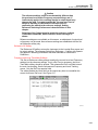
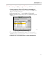
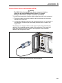
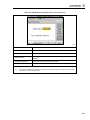
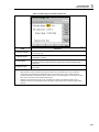
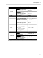
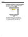
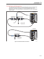
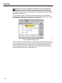
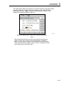
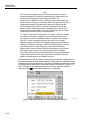
1
96000 Series RF Reference Source Operators Manual May 2014 © 2014 Fluke Corporation. All rights reserved. Specifications are subject to change without notice. All product names are trademarks of their respective companies. LIMITED WARRANTY AND LIMITATION OF LIABILITY Each Fluke product is warranted to be free from defects in material and workmanship under normal use and service. The warranty period is one year and begins on the date of shipment. Parts, product repairs, and services are warranted for 90 days. This warranty extends only to the original buyer or end-user customer of a Fluke authorized reseller, and does not apply to fuses, disposable batteries, or to any product which, in Fluke's opinion, has been misused, altered, neglected, contaminated, or damaged by accident or abnormal conditions of operation or handling. Fluke warrants that software will operate substantially in accordance with its functional specifications for 90 days and that it has been properly recorded on non-defective media. Fluke does not warrant that software will be error free or operate without interruption. Fluke authorized resellers shall extend this warranty on new and unused products to end-user customers only but have no authority to extend a greater or different warranty on behalf of Fluke. Warranty support is available only if product is purchased through a Fluke authorized sales outlet or Buyer has paid the applicable international price. Fluke reserves the right to invoice Buyer for importation costs of repair/replacement parts when product purchased in one country is submitted for repair in another country. Fluke's warranty obligation is limited, at Fluke's option, to refund of the purchase price, free of charge repair, or replacement of a defective product which is returned to a Fluke authorized service center within the warranty period. To obtain warranty service, contact your nearest Fluke authorized service center to obtain return authorization information, then send the product to that service center, with a description of the difficulty, postage and insurance prepaid (FOB Destination). Fluke assumes no risk for damage in transit. Following warranty repair, the product will be returned to Buyer, transportation prepaid (FOB Destination). If Fluke determines that failure was caused by neglect, misuse, contamination, alteration, accident, or abnormal condition of operation or handling, including overvoltage failures caused by use outside the product’s specified rating, or normal wear and tear of mechanical components, Fluke will provide an estimate of repair costs and obtain authorization before commencing the work. Following repair, the product will be returned to the Buyer transportation prepaid and the Buyer will be billed for the repair and return transportation charges (FOB Shipping Point). THIS WARRANTY IS BUYER'S SOLE AND EXCLUSIVE REMEDY AND IS IN LIEU OF ALL OTHER WARRANTIES, EXPRESS OR IMPLIED, INCLUDING BUT NOT LIMITED TO ANY IMPLIED WARRANTY OF MERCHANTABILITY OR FITNESS FOR A PARTICULAR PURPOSE. FLUKE SHALL NOT BE LIABLE FOR ANY SPECIAL, INDIRECT, INCIDENTAL, OR CONSEQUENTIAL DAMAGES OR LOSSES, INCLUDING LOSS OF DATA, ARISING FROM ANY CAUSE OR THEORY. Since some countries or states do not allow limitation of the term of an implied warranty, or exclusion or limitation of incidental or consequential damages, the limitations and exclusions of this warranty may not apply to every buyer. If any provision of this Warranty is held invalid or unenforceable by a court or other decision-maker of competent jurisdiction, such holding will not affect the validity or enforceability of any other provision. Fluke Corporation P.O. Box 9090 Everett, WA 98206-9090 U.S.A. 11/99 Fluke Europe B.V. P.O. Box 1186 5602 BD Eindhoven The Netherlands Table of Contents Chapter 1 Title Introduction and Specifications ......................................................... 1-1 About the Manual .............................................................................................. Contacting Fluke ................................................................................................ Safety Information ............................................................................................. Symbols ......................................................................................................... General Safety Summary ............................................................................... Prevent Instrument Damage .......................................................................... Instrument Description ...................................................................................... Options and Accessories .................................................................................... Specifications ..................................................................................................... General Specifications (96040A and 96270A) .............................................. Frequency Reference Input/Output Specifications (96040A and 96270A) ... Leveled Sine Specifications at Leveling Head Output (96040A and 96270A) ......................................................................................................... Leveled Sine Specifications at Microwave Output (96270A) ....................... Leveled Sine Specifications at Leveling Head Output (96040A and 96270A) and Microwave Output (96270A) .................................................. Modulation Specifications at Leveling Head Output (96040A and 96270A) and Microwave Output (96270A) .................................................. Frequency Sweep Specifications at Leveling Head Output (96040A and 96270A) and Microwave Output (96270A) .................................................. Frequency Counter Specifications ................................................................. Power Meter Readout Specifications (96270A only) .................................... GPIB Command Emulation Mode Specifications ......................................... 2 Page 1-1 1-1 1-2 1-2 1-3 1-4 1-6 1-7 1-10 1-10 1-11 1-11 1-13 1-15 1-17 1-20 1-21 1-21 1-21 Prepare the Instrument for Operation ............................................... 2-1 Introduction ........................................................................................................ Unpack and Inspect the Instrument.................................................................... Store and Ship the Instrument ............................................................................ Power Considerations ........................................................................................ Replace the Power Cord ................................................................................ Power-On Sequence ...................................................................................... Power-On Self-Test ....................................................................................... Power-On State .............................................................................................. iii 2-1 2-1 2-2 2-3 2-3 2-5 2-5 2-6 96000 Series Operators Manual Leveling Head Connections (96270A and 96040A) .......................................... Microwave Output Connections (96270A) ........................................................ Power Sensor Connections (96270A)............................................................ Install the Instrument in an Equipment Rack ..................................................... Cooling Considerations...................................................................................... User-Initiated Self-Test...................................................................................... Running Self-Test .......................................................................................... Review the Results ........................................................................................ Operator Maintenance........................................................................................ Clean the Instrument...................................................................................... Clean the Air Filter ........................................................................................ Replace the Line-Power Fuses ...................................................................... Firmware ............................................................................................................ Performance Test and Calibration ..................................................................... 3 2-7 2-8 2-8 2-8 2-8 2-9 2-10 2-11 2-12 2-12 2-12 2-13 2-15 2-15 Local Operation ................................................................................... 3-1 Introduction ........................................................................................................ Controls, Indicators, and Connectors ................................................................. Leveling Head I/O Connectors ...................................................................... Microwave Output Connector (96270A) ....................................................... Output Connector Status Indicators (96270A) .............................................. Sensor Connectors (96270A)......................................................................... USB Storage Port (96270A) .......................................................................... STBY/OPER (Standby/Operate) ................................................................... Function Keys ................................................................................................ Signal Source Keys ................................................................................... MEAS (Measurements) Key ..................................................................... UNITS Key ............................................................................................... SETUP Key ............................................................................................... SIGNAL Key (96270) ............................................................................... Display ...................................................................................................... Data Fields ................................................................................................ Soft Labels ................................................................................................ Softkeys ..................................................................................................... Status Bar .................................................................................................. Field Editor .................................................................................................... Cursor Keys............................................................................................... Spin Wheel ................................................................................................ Keypad........................................................................................................... Alphanumeric Keys ................................................................................... ALPHA Key .............................................................................................. NEXT CHAR Key .................................................................................... BKSP Key (Backspace) ............................................................................ SPACE Key ............................................................................................... EXP Key (Exponent)................................................................................. ENTER Key .............................................................................................. Screen Controls and Indicators .......................................................................... Main RF Output Screens ............................................................................... Edit Modes – The Vertical Softkeys.............................................................. Expanded Settings – The Horizontal Softkeys .............................................. Preferences Softkey ................................................................................... Offset Softkey ........................................................................................... Toggle Offset Softkey ............................................................................... Offset (As Error) Softkey .......................................................................... Reference Softkeys.................................................................................... iv 3-1 3-2 3-5 3-5 3-5 3-5 3-6 3-6 3-6 3-7 3-7 3-7 3-7 3-9 3-9 3-10 3-11 3-11 3-12 3-12 3-12 3-13 3-13 3-13 3-13 3-13 3-13 3-13 3-13 3-14 3-14 3-14 3-15 3-19 3-19 3-20 3-21 3-21 3-22 Contents (continued) Reference Off Softkey............................................................................... Frequency and Level Track Main Softkeys .............................................. Rear-Panel Controls and Connectors ................................................................. Power Block and Switch ............................................................................... IEEE 488 Connector ...................................................................................... Reference Frequency Output Connector ....................................................... Reference Frequency Input Connector .......................................................... 50 MHz Frequency Counter, Modulation, Leveling and Frequency Pull Input Connector...................................................................................... 300 MHz Frequency Counter Input Connector (96270A) ............................. Trigger I/O Connector ................................................................................... Instrument Operation ......................................................................................... Before Starting............................................................................................... Set Global Preferences .................................................................................. Local or Remote Operation ........................................................................... GPIB Command Emulation ........................................................................... Select and Change the Address of a Command Emulation ........................... Connect a Leveling Head to the Instrument .................................................. Connect a Leveling Head to a Unit Under Test............................................. Connect the Microwave Output to a Unit Under Test (96270A) .................. Connect a Power Sensor to the Instrument (96270A) .................................... Connect a Power Sensor to a Unit Under Test (96270A 0nly) ...................... Save/Recall and Master Reset Function ........................................................ Access the Memory Screen ....................................................................... Make a Memory Selection ........................................................................ Rename a Selection ................................................................................... Delete a Selection ...................................................................................... Save an Instrument Setup .......................................................................... Save Settings for a Function ..................................................................... Recall Settings........................................................................................... Create an RF Output Signal ........................................................................... Output Signal Routing (96270A) .................................................................. Leveled Sine Output Signal ........................................................................... Leveled Sine Preferences .......................................................................... Sensor Leveling and Sensor Leveling Preferences (96270A) ................... Rear Input Preferences .............................................................................. Display Layout Preferences (96270A) ...................................................... Frequency Pull Preferences ....................................................................... Externally Leveled Sine Preferences......................................................... Enhanced Frequency Resolution ............................................................... Reference Switching Preferences .............................................................. Define the Leveled-Sine Output Signal .................................................... Apply an Offset to a Leveled-Sine Output Signal..................................... Modulated Output Signal .............................................................................. Set Modulation Preferences ...................................................................... Define an Amplitude-Modulated Output Signal ....................................... Apply an Offset to an Amplitude-Modulated Output Signal .................... Create a Frequency-Modulated Output Signal .......................................... Apply an Offset to a Frequency-Modulated Output Signal ...................... Phase-Modulated Output Signal ............................................................... Apply an Offset to a Phase-Modulated Output Signal .............................. Sweep Output Signal ..................................................................................... Set the Sweep Preferences ........................................................................ Define a Swept-Frequency Output Signal ................................................. Narrow Range Locked Sweep ................................................................... v 3-23 3-23 3-24 3-25 3-25 3-25 3-25 3-26 3-29 3-30 3-32 3-32 3-32 3-33 3-34 3-35 3-37 3-39 3-41 3-43 3-44 3-45 3-45 3-46 3-46 3-46 3-47 3-47 3-47 3-48 3-49 3-52 3-52 3-56 3-58 3-59 3-60 3-61 3-64 3-65 3-66 3-69 3-70 3-70 3-71 3-73 3-76 3-80 3-80 3-84 3-84 3-85 3-87 3-88 96000 Series Operators Manual 50 MHz Frequency Counter (96040A) .......................................................... 300 MHz Frequency Counter (96270A) ........................................................ Power Meter Readout (96270A).................................................................... Power Meter Readout Selections ................................................................... Power Readout Units ..................................................................................... Set the Measurement Frequency.................................................................... Set Power Sensor Preferences ....................................................................... Power Reading Averaging and Triggering .................................................... Relative Power Measurements ...................................................................... Change Units for Relative Power Measurements .......................................... Profiles (96270A) .......................................................................................... Profiles Overview...................................................................................... Profile File Format and File Naming Requirements ................................. Select and Apply Profiles .......................................................................... Import Profiles .......................................................................................... Export Profiles .......................................................................................... Profile Self Measure (Self-Characterization) ............................................ Measurement Integrity at High Signal Levels ............................................... Measurement Integrity at Low Signal Levels................................................ Eliminate Interference from the Ether ....................................................... Eliminate Interference from System Clocks – Common Mode and Ether Borne ............................................................................................... Avoid Grounding RF Common on the Instrument.................................... Verify the Level of an Interfering Signal .................................................. De-tune the Interfering Signal ................................................................... vi 3-90 3-92 3-94 3-95 3-97 3-98 3-99 3-100 3-102 3-103 3-103 3-103 3-106 3-107 3-110 3-111 3-113 3-118 3-118 3-119 3-119 3-120 3-120 3-120 List of Tables Table 1-1. 1-2. 1-3. 2-1. 2-2. 2-3. 2-4. 3-1. 3-2. 3-3. 3-4. 3-5. 3-6. 3-7. 3-8. 3-9. 3-10. 3-11. 3-12. 3-13. 3-14. 3-15. 3-16. 3-17. 3-18. 3-19. 3-20. 3-21. 3-22. 3-23. 3-24. 3-25. 3-26. 3-27. 3-28. Title Symbols .................................................................................................................. List of Options and Accessories for 96270A ......................................................... List of Options and Accessories for 96040A ......................................................... List of Contents ...................................................................................................... Dimensions for a Substitute Cushioned Shipping Container ................................. Power Cord for Various Regions ........................................................................... Power Input Fuse.................................................................................................... Compatible Power Sensors..................................................................................... Reference Frequency Output Specifications .......................................................... Reference Frequency Input Specifications ............................................................. External Modulation Input Specification (FM and PM) ........................................ External Modulation Input Specification (AM) ..................................................... External Leveling Input Specification.................................................................... External Frequency Pull Input Specification.......................................................... 50 MHz Frequency Counter Input Specifications (96040A). ............................... 300 MHz Frequency Counter Input Specifications (96270A) ............................... Sweep Trigger Input Specification ......................................................................... Sweep Trigger Output Specification ...................................................................... Modulation Trigger Output Specifications............................................................. Global Preferences ................................................................................................. 96040A Leveled - Sine Preferences ....................................................................... 96270A Leveling Head Output Leveled - Sine Preferences .................................. 96270A Microwave Output Leveled - Sine Preferences ........................................ Sensor Leveling Preferences .................................................................................. Frequency Pull Preferences .................................................................................... Externally Leveled Sine Preferences...................................................................... Selection of Frequency Resolution ........................................................................ Reference Switching Preferences ........................................................................... Leveled-Sine Fields for 960404A and 96270 Leveling Head Output .................... 96270A Leveled-Sine Fields for Microwave Output ............................................. Modulation Preferences Fields ............................................................................... Amplitude-Modulation Fields ................................................................................ Frequency-Modulation Fields ................................................................................ Phase Modulation Fields ........................................................................................ Sweep Preferences Fields ....................................................................................... vii Page 1-2 1-8 1-9 2-2 2-3 2-4 2-14 3-6 3-25 3-25 3-27 3-28 3-28 3-28 3-29 3-29 3-31 3-31 3-31 3-33 3-53 3-54 3-55 3-57 3-61 3-63 3-64 3-65 3-67 3-68 3-70 3-74 3-78 3-82 3-86 96000 Series Operators Manual 3-29. 3-30. 3-31. 3-32. 3-33. Sweep-Frequency Fields ........................................................................................ 96040A Frequency Counter Readout and Fields ................................................... 96270A Frequency Counter Readout and Fields ................................................... Power Meter Sensor Preferences............................................................................ Setup Profiles Screen ............................................................................................. viii 3-89 3-91 3-93 3-99 3-105 List of Figures Figure 1-1. 1-2. 2-1. 2-2. 2-3. 2-4. 2-5. 2-6. 3-1. 3-2. 3-3. 3-4. 3-5. 3-6. 3-7. 3-8. 3-9. 3-10. 3-11. 3-12. 3-13. 3-14. 3-15. 3-16. 3-17. 3-18. 3-19. 3-20. 3-21. 3-22. 3-23. 3-24. 3-25. 3-26. 3-27. Title 96270A RF Reference Source ................................................................................ 96040A RF Reference Source ................................................................................ First Power-On Screen ........................................................................................... First Power-On Screen (GPIB emulation mode), HP3335 Personality .................. Select a Self-Test Sequence ................................................................................... Summary of Self-Test Results................................................................................ Expanded Self-Test Failure Results ....................................................................... Access the Fuse ...................................................................................................... Front-Panel Controls, Indicators, and Connectors ................................................. Setup Screen ........................................................................................................... Calibration Screen .................................................................................................. Signal Status Screen ............................................................................................... Leveled Sine Screen ............................................................................................... Status Bar ............................................................................................................... Control Screens for the RF Output Signal ............................................................. Leveled Sine ........................................................................................................... Step Edit ................................................................................................................. Keypad Edit ............................................................................................................ Measurement Units ................................................................................................ Modulation Preferences.......................................................................................... Leveled Sine – No Offset ....................................................................................... Leveled Sine – Offset Applied ............................................................................... Leveled Sine - Toggle Offset ................................................................................. Monitoring the References ..................................................................................... Frequency and Level Tracking ............................................................................... Rear-Panel Controls and Connectors ..................................................................... Instrument Setup Screen......................................................................................... Leveled Sine – Remote Operation ......................................................................... GPIB Preferences (9640A selected) ....................................................................... 3335 GPIB Preferences - GPIB Address................................................................ 9640A GPIB Preferences Model (Entry) ............................................................... Connect the Leveling Head .................................................................................... Microwave Output Connections (96270A) ............................................................ Connect the Power Sensor(s) (96270A) ................................................................. Save/Recall Screen ................................................................................................. ix Page 1-7 1-7 2-6 2-7 2-10 2-11 2-11 2-14 3-2 3-7 3-8 3-9 3-10 3-12 3-14 3-16 3-17 3-18 3-18 3-19 3-20 3-20 3-21 3-22 3-23 3-24 3-32 3-34 3-35 3-36 3-36 3-38 3-42 3-43 3-45 96000 Series Operators Manual 3-28. 3-29. 3-30. 3-31. 3-32. 3-33. 3-34. 3-35. 3-36. 3-37. 3-38. 3-39. 3-40. 3-41. 3-42. 3-43. 3-44. 3-45. 3-46. 3-47. 3-48. 3-49. 3-50. 3-51. 3-52. 3-53. Control Screens for the RF Output Signal ............................................................. Leveling Head Output (96040A and 96270A) ....................................................... Microwave Output (96270A) ................................................................................. Microwave Output and HF Leveling Kit (96270A Leveled Sine) ......................... Rear Input Preferences Screen ............................................................................... Source/Measure Display Layout ............................................................................ Instrument Screens with Power Meter Readouts ................................................... Power Meter Screen ............................................................................................... Signal Status Screen ............................................................................................... Source/Measure Screen .......................................................................................... Power Readout Units Selection .............................................................................. Power Meter Screen-Setting Frequency ................................................................. Power Meter Screen (Trigger Single Selected) ...................................................... Power Meter Screen - Relative Measurement ........................................................ Setup Profile Screen - Profile Applied ................................................................... Signal Status Screen- Selected Profile Not Applied .............................................. Signal Status Screen- Profile Applied .................................................................... Profile Import Screen - Memory Stick Files Shown .............................................. Profile Import Screen - Memory Stick Directories Shown .................................... Profile Export Screen- Memory Stick Directories Shown ..................................... Self-Characterization Connections ......................................................................... Measure Profile Screen .......................................................................................... Measure Profile – Measurement Points Units Selection ........................................ Measure Profile Screen - Leveling Head Output Selected ..................................... Measure Profile Screen - Microwave Output Selected .......................................... Measure Profile Screen – Measurement Complete ................................................ x 3-48 3-49 3-50 3-51 3-58 3-59 3-94 3-95 3-95 3-96 3-97 3-98 3-101 3-102 3-107 3-108 3-109 3-110 3-111 3-111 3-113 3-114 3-115 3-116 3-117 3-118 Chapter 1 Introduction and Specifications About the Manual The 96000 Series RF Reference Source (hereafter referred to as the 96000 Series, Instrument, or Product) and their options and accessories are described in this manual. All information necessary to operate and maintain the Instruments effectively are included. Unless otherwise stated, the descriptions of functionality and operation are common to all 96000 Series models. Where relevant, any differences between models are indicated and described. Contacting Fluke To contact Fluke Calibration, call one of the following telephone numbers: • Technical Support USA: 1-877-355-3225 • Calibration/Repair USA: 1-877-355-3225 • Canada: 1-800-36-FLUKE (1-800-363-5853) • Europe: +31-40-2675-200 • Japan: +81-3-6714-3114 • Singapore: +65-6799-5566 • China: +86-400-810-3435 • Brazil: +55-11-3759-7600 • Anywhere in the world: +1-425-446-6110 To see product information or download manuals and the latest manual supplements, visit Fluke Calibration’s website at www.flukecal.com. To register your product, visit http://flukecal.com/register-product. 1-1 96000 Series Operators Manual Safety Information This section addresses safety considerations and describes symbols that may appear either in this manual or on the Instrument. A Warning statement identifies conditions or practices that could result in injury or death. A Caution statement identifies conditions or practices that could result in damage to the Instrument or equipment to which it is connected. Warning To prevent possible electrical shock, fire, or personal injury, carefully read the information under General Safety Summary before attempting to install, use, or service the Product. Symbols The safety and electrical symbols shown in Table 1-1 may appear on the Instrument or in this manual. Table 1-1. Symbols Symbol Symbol Meaning Risk of Danger. Important information. See Manual. Earth Terminal Hazardous voltage. Risk of electric shock. Recycle IO Power ON / OFF Conforms to European Union directives. 1-2 Meaning Intertek ETL listed mark for CSA C22.2, 61010-1 and UL 61010-1 Conforms to relevant Australian EMC standards Conforms to relevant South Korean EMC standards. AC (Alternating Current) This product complies with the WEEE Directive (2002/96/EC) marking requirements. The affixed label indicates that you must not discard this electrical/electronic product in domestic household waste. Product Category: With reference to the equipment types in the WEEE Directive Annex I, this product is classed as category 9 "Monitoring and Control Instrumentation" product. Do not dispose of this product as unsorted municipal waste. Go to Fluke’s website for recycling information. Introduction and Specifications Safety Information 1 General Safety Summary This manual contains information and warnings that must be observed to keep the Instrument in a safe condition and ensure safe operation. Using or servicing the Instrument in conditions other than as specified in this manual could compromise your safety. To use the Instrument correctly and safely, read and follow the precautions on the next few pages, as well as the safety instructions or warnings given throughout this manual. In addition, follow all generally accepted safety practices and procedures when working with and around electricity. Warning To prevent possible electrical shock, fire, or personal injury: • • • • • • • • • • • • • • • • • • • Read all safety information before you use the Product. Carefully read all instructions. Use the Product only as specified, or the protection supplied by the Product can be compromised. Do not use the Product if it operates incorrectly. Do not use the Product around explosive gas, vapor, or in damp or wet environments. Disable the Product if it is damaged. Do not use the Product if it is damaged. Use this Product indoors only. Use only the mains power cord and connector approved for the voltage and plug configuration in your country and rated for the Product. Do not apply hazardous voltages to any connector other than the mains supply to the mains input. Make sure the ground conductor in the mains power cord is connected to a protective earth ground. Disruption of the protective earth could put voltage on the chassis that could cause death. Replace the mains power cord if the insulation is damaged or if the insulation shows signs of wear. If the mains power cord is to be the accessible disconnect device, the mains power cord must not be longer than 3 meters (118.1 inches). Turn the Product off and remove the mains power cord. Stop for 2 minutes to let the power assemblies discharge before you open the fuse door. Do not operate the Product with covers removed or the case open. Hazardous voltage exposure is possible. Restrict the humidity of the operating environment to the level specified for any equipment used that conforms to IEC60950-1 used with the Product. Remove the input signals before you clean the product. Use only specified replacement parts. Use only specified replacement fuses. 1-3 96000 Series Operators Manual • • • • Have an approved technician repair the Product. Do not apply more than the rated voltage, between the terminals or between each terminal and earth ground. Use good lifting practices when lifting or moving the Product. The Product is an unbalanced load and can weigh as much as 18 kg (40 pounds). After the equipment has been taken apart, ensure that the mains wiring connections have been correctly restored. Two protective earth nuts are tightened to 1.5 Nm, the covers are fitted securely and the mains insulation/earth resistances has been checked using portable appliance test equipment. Prevent Instrument Damage Caution To prevent possible damage to the Product or to equipment under test: 1-4 • The front panel Head RF Output and Head Control connectors on the Product are suited only for use with Fluke 96040A-xx Leveling Heads or the 9600FLT 1-GHz Wide Offset Filter. Only compatible power sensors should be connected to the front panel Sensor connectors. No other connections are permitted. • The Leveling Heads are fitted with close tolerance metrology grade N-connectors compliant with MIL-C-39012 and MMC Standards for Precision N-connectors. When used in demanding metrology applications the Leveling Heads are likely to be mated with similar high-quality connectors, thus, minimizing the opportunity for wear and damage. However, in applications that require frequent mating or mating to lower quality connectors, the opportunity for damaging the connectors increases. On these high-risk occasions, consider using a sacrificial adapter to prevent damage to the N connectors. • Improper mating of 50 Ω and 75 Ω connectors will cause irreversible damage the center pin. Although appearance is similar, the dimensions (pin diameter) of 75 Ω differ significantly from those of 50 Ω. Make sure that the 50 Ω Leveling Head is mated only to 50 Ω systems and, likewise, that the 75 Ω Leveling Head is mated only with 75 Ω systems. Otherwise, mechanical damage of metrologygrade connectors and out-of-tolerance performance is likely to occur. Introduction and Specifications Safety Information • Very high-grade flexible coaxial transmission line conducts the RF input signal to 96040A-xx Leveling Heads. As with any coaxial line, deformation of sidewalls or abrupt bending can degrade performance. Take care to avoid mechanical stress or tight bend radius < 60 mm (2.4 in). • Critical connector mating dimensions could be damaged during disassembly of a Leveling Head. DO NOT TAMPER with the four mounting screws at the base of the N-Connector. Leveling Head disassembly should only be performed by qualified service personnel at a Fluke Service Center. • The optional power sensor(s) contain components which can be destroyed by electrostatic discharges. To prevent this, never touch the sensor RF connector inner conductor and never open the sensor. Never exceed the sensor maximum RF power limit. Even brief overloads can destroy the sensor. • Reliable and repeatable RF interconnections are achieved only at specified torque settings. Performance will be impaired if torque settings are not observed, and permanent connector damage is likely to result from over-tightening. • To prevent damage to the Product, do not use aromatic hydrocarbons or chlorinated solvents for cleaning. • To prevent the public transmission of an unintentional RF signal, never connect the Product output to an antenna outside a shielded room. 1 1-5 96000 Series Operators Manual Instrument Description The Instruments are RF Reference instruments designed to create and measure the signals necessary for precision RF and microwave applications. The 96040A model provides outputs up to 4 GHz. See Figure 1-1. The 96270A provides outputs up to 27 GHz and includes integrated power meter readout capability. See Figure 1-2. Signal delivery that uses interchangeable Leveling Heads from 1 mHz to 4 GHz in both models ensures a unique combination of level accuracy, dynamic range, and frequency coverage in both 50 Ω and 75 Ω systems. The 96270A model adds frequency coverage from 1 mHz up to 27 GHz delivered with the 50 Ω microwave output directly or optionally via a splitter and power sensor combination. In all cases, the actual signal level delivered to the UUT (Unit Under Test) at the selected output is set and shown directly at the Instrument front panel or remote interface. The subsequent list of features let you integrate the Instrument into a typical RF calibration system: • Accurate level / attenuation over a wide dynamic range • Precision internal AM/FM modulation, including External Modulation capability • Frequency Range includes LF, RF, and microwave • High signal purity with no additional filtering, and extremely low phase noise and jitter • Leveling Heads to ensure direct and precise signal delivery to the load • Integrated dual channel power meter readout (96270A). • USB port for profile data transfer (only supports memory stick, not available on 96040A.) • Integrated 300 MHz Frequency Counter (50 MHz in 96040A) • IEEE 488 Remote Interface • Remote command emulation of the 9640A RF Reference Source and some other signal generators • Rack Mount Slide Kit (optional) • 1 GHz Wide Offset Phase Noise Filter (optional) 1-6 Introduction and Specifications Options and Accessories 1 hpn317.eps Figure 1-1. 96040A RF Reference Source hpn316.eps Figure 1-2. 96270A RF Reference Source Options and Accessories Table 1-2 and Table 1-3 provide a list of the instruments, options and accessories available. When ordering an option or accessory after the original purchase, include a reference to the Instrument as well as the description from the subsequent table. 1-7 96000 Series Operators Manual Table 1-2. List of Options and Accessories for 96270A Option/Accessory Explanation Mainframe with 4 GHz 50 Ω Leveling Head and this manual set: 96270A 96270A/LL • Printed Safety Information Sheet • CD with the complete manual set including the Operators and Service Manual With extended Low-Level Microwave Output. Internal step attenuator extending Microwave output level range minimum from -4 dBm to -100 dBm. This is a factory/service upgrade that requires the return of the main Instrument and partner leveling heads. With HF Leveling Kit. The kit includes: 96270A/HF 96000SNS • 1 - 2.92 mm, 40 GHz Power Sensor • 1 - Precision PC3.5, 26.5 GHz Power Splitter • 1 - Precision 2.92 male/2.92 male Adapter • 1 - Precision Metrology Grade 1 m Coax Cable Additional 2.92 mm, 40 GHz Power Sensor RF Interconnect Kit. The kit includes: • 96000CONN 1-8 1 – Interconnect N (f) to N (f) Adapter 50 Ω • 1 – Sacrificial N (f) to N (m) Adapter 50 Ω • 1 – Interseries N (f) to PC3.5 (m) Adapter • 1 – Interseries N (f) to PC3.5 (f) Adapter • 1 – Interseries N (m) to PC3.5 (m) Adapter • 1 – Sacrificial PC3.5 (m) to PC3.5 (f) Adapter • 1 – Characterisation PC3.5 (f) to PC3.5 (f) Adapter • 1 – 8 mm Torque Wrench • 1 – 20 mm Torque Wrench 96000A/75 96040A-75 4 GHz, 75 Ω Leveling Head 9600FLT 1 GHz Wide Offset Phase Noise Filter, including Instrument Mounting Kit Y9600 Rack Mount Slide kit 96270A/S Remove USB Port 96000CASE Rugged Transit Case Introduction and Specifications Options and Accessories 1 Table 1-3. List of Options and Accessories for 96040A Option/Accessory Explanation Mainframe with 4 GHz 50 Ω Leveling Head and Manual and this manual set: 96040A • Printed Safety Information Sheet • CD with the complete manual set (PDF files), including the Operators and Service Manual RF Interconnect Kit. The kit includes: 9600CONN • 1 – Sacrificial N-Connector, Male to Female Adapter, 50 Ω • 1 – Precision N-Connector, Female to Female Adapter, 50 Ω • 1 – 8 mm Torque Wrench • 1 – 20 mm Torque Wrench 96000A/75 4 GHz, 75 Ω Leveling Head 9600FLT 1 GHz Wide Offset Phase Noise Filter, including Instrument Mounting Kit Y9600 Rack Mount Slide kit 96000CASE Rugged Transit Case 1-9 96000 Series Operators Manual Specifications General Specifications (96040A and 96270A) Performance All specifications apply to a 1-year calibration interval at an ambient temperature of Tcal ±5 °C. Nominal factory Tcal calibration temperature 23 °C. Unless otherwise noted, specifications are stated at a 99 % confidence level Standard Interfaces IEEE488.2 (GPIB) [1] 96270A only: Compatible power sensor inputs 96270A only: USB memory device Warmup Time 60 minutes Temperature Operating: 0 °C to 50 °C Specified Operation: 5 °C to 40 °C Storage: -20 °C to +70 °C Relative Humidity Operating or Storage: Non-condensing, 5 °C to 30 °C <90 %, <40 °C <75 %, <70 °C <45 % Altitude Operating: ≤2,000 m Non-operating: ≤12,000 m Safety EN 61010-1: Pollution Degree 2, Installation Category II Electromagnetic Compatibility EN 61326-1: Controlled Applies to use in Korea only. Class A Equipment (Industrial Broadcasting & [2] Communication Equipment) [2] This product meets requirements for industrial (Class A) electromagnetic wave equipment and the seller or user should take notice of it. This equipment is intended for use in business environments and is not to be used in homes. Line Power Voltage: 100 V to 240 V rms with additional voltage fluctuations of ±10 %. Frequency: 50 Hz to 60 Hz with additional frequency variation of ±3 Hz. Power Consumption 250 VA Dimensions 442 mm (17.4 in) wide, 146 mm (5.76 in) high and 551 mm (21.7 in) deep, including handles. Mounts within industry-standard 483 mm (19 in) rack-mount frames when fitted with Y9600 rack mounting kit. Weight 18 kg (40 lb) [1] See Power Meter Readout specifications for compatible power sensor details. 551 mm (21.7") 133 mm (5.24") 146 mm (5.75") 442 mm (17.4") hpn366eps 96040A and 96270A Dimensions 1-10 Introduction and Specifications Specifications 1 Frequency Reference Input/Output Specifications (96040A and 96270A) Frequency Reference Input Rear-panel Reference Frequency Input BNC connector Frequency 1 MHz to 20 MHz in 1 MHz steps ±0.3 ppm, typical Level 1 V pk nominal into 50 Ω, ±5 V pk max Frequency Reference Output Rear-panel Reference Frequency Output BNC connector Frequency 1 MHz or 10 MHz, user selectable Level 1.5 V pk-pk into 50 Ω, 3 V pk-pk into 1 kΩ, TTL compatible Accuracy [1] [2] Ageing Rate and Stability [1] [2] ±0.05 ppm [2] -10 After 24-hr warmup: ≤±5x10 /day, typical -8 -8 Continuous operation: ≤±2x10 /month typical, ≤±5x10 over 1 year Includes all stability effects for the 1-year calibration interval and Tcal ±5 °C temperature range applicable to all specifications. Specifications apply only if Internal Frequency Reference operation is selected. With External Frequency Reference operation selected, the frequency of the Frequency Reference Output is locked to the signal applied to the Frequency Reference Input. Leveled Sine Specifications at Leveling Head Output (96040A and 96270A) Frequency Range 1 mHz to 4 GHz Resolution Standard: <100 MHz: 0.001 Hz (1 mHz), ≥100 MHz: 11 digits Enhanced: 0.000 01 Hz (10 μHz) Accuracy Internal Frequency Reference: ±0.05 ppm ± 5 μHz External Frequency Reference: Ext Freq Ref Accuracy ±5 μHz 50 Ω Output Amplitude 75 Ω Output Output Connector Precision 50 Ω N-Series male Precision 75 Ω N-Series male Range -130 dBm to +24 dBm (0.2 μV to 10 V pk-pk) >125 MHz: +20 dBm >1.4 GHz: +14 dBm -130 dBm to +18 dBm (0.13 μV to 6.3 V pk-pk) >125 MHz: +14 dBm >1.4 GHz: +8 dBm Resolution 0.001 dB 0.001 dB VSWR ≤100 MHz: ≤1.05 ≤2 GHz: ≤1.1 2 GHz to 4 GHz: ≤1.0 + 0.05 x f (GHz) ≤100 MHz: ≤1 GHz: ≤2 GHz: ≤1.1 ≤1.2 ≤1.3 1-11 96000 Series Operators Manual 50 Ω Output Attenuation Attenuation [1] 100 kHz to 128 MHz Cumulative and Incremental Attenuation To determine the attenuation specification between any two [2] output levels, apply an RSS summation of the dB values listed for each output level. [1] [2] 75 Ω Output Relative to +16 dBm output Relative to +10 dBm output 0 dB to 55 dB ±0.02 dB 55 dB to 64 dB ±0.03 dB 64 dB to 74 dB ±0.05 dB 74 dB to 100 dB ±0.07 dB [1] 100 dB to 116 dB ±0.15 dB Relative to any level between +16 dBm and -100 dBm, 10 Hz to 128 MHz 0 dB to 33 dB 33 dB to 64 dB 64 dB to 100 dB [1] 100 dB to 110 dB +16 to -39 dBm -39 to -48 dBm -48 to -58 dB -58 to -84 dBm -84 to -100 dBm ±0.02 dB ±0.03 dB ±0.05 dB ±0.07 dB ±0.15 dB ±0.07 dB ±0.1 dB ±0.2 dB ±0.4 dB Relative to any level between +10 dBm and -100 dBm, 10 Hz to 128 MHz +10 dBm to -23 dBm -23 dBm to -54 dBm -54 dBm to -90 dBm -90 dBm to -100 dBm ±0.07 dB ±0.1 dB ±0.2 dB ±0.4 dB Specifications are typical at attenuation of more than 64 dB up to 20 kHz, at more than 96 dB up to 100 kHz, and at more than 100 dB at all frequencies. Root Sum Square. 50 Ω Output Absolute Amplitude Accuracy Amplitude [1] >300 MHz to 1.4 GHz >1.4 GHz to 3 GHz >3 GHz to 4 GHz 10 Hz to <100 kHz 100 kHz >100 kHz to <10 MHz 10 MHz to 128 MHz >+20 to +24 ±0.03 dB ±0.03 dB ±0.05 dB ±0.05 dB >+14 to +20 ±0.03 dB ±0.03 dB ±0.05 dB ±0.05 dB ±0.07 dB ±0.2 dB -17 to +14 ±0.03 dB ±0.03 dB ±0.05 dB ±0.05 dB ±0.07 dB ±0.2 dB ±0.3 dB ±0.3 dB -48 to <-17 ±0.03 dB ±0.03 dB ±0.05 dB ±0.05 dB ±0.07 dB ±0.2 dB ±0.3 dB ±0.5 dB ±0.2 dB ±0.2 dB ±0.1 dB ±0.1 dB ±0.4 dB ±0.5 dB ±0.5 dB ±0.5 dB ±0.5 dB ±0.1 dB ±0.3 dB ±0.5 dB ±1.0 dB ±1.0 dB ±0.5 dB ±0.5 dB ±0.3 dB ±0.5 dB ±1.0 dB ±1.0 dB ±0.7 dB ±1.5 dB ±1.5 dB ±1.5 dB >-74 to <-48 >-84 to -74 >-94 to -84 Not Specified -130 to -94 [1] 1-12 >128 MHz to 300 MHz dBm Also applies as typical accuracy at frequencies <10 Hz. Output not available Not Specified Introduction and Specifications Specifications Amplitude Flatness relative to 100 kHz 1 50 Ω Output Amplitude [1] dBm 10 Hz to <100 kHz 100 kHz >100 kHz to <10 MHz 10 MHz to 128 MHz >+20 to +24 ±0.03 dB ±0.00 dB ±0.04 dB ±0.04 dB >+14 to +20 ±0.03 dB ±0.00 dB ±0.04 dB ±0.04 dB ±0.06 dB ±0.2 dB -17 to +14 ±0.03 dB ±0.00 dB ±0.04 dB ±0.04 dB ±0.06 dB ±0.2 dB ±0.3 dB ±0.3 dB -48 to <-17 ±0.03 dB ±0.00 dB ±0.04 dB ±0.04 dB ±0.06 dB ±0.2 dB ±0.3 dB ±0.5 dB >-74 to <-48 ±0.00 dB ±0.2 dB ±0.1 dB ±0.1 dB ±0.4 dB ±0.5 dB ±0.5 dB >-84 to -74 ±0.00 dB ±0.5 dB ±0.1 dB ±0.3 dB ±0.5 dB ±1.0 dB ±1.0 dB >-94 to -84 ±0.00 dB ±0.5 dB ±0.3 dB ±0.5 dB ±1.0 dB ±1.0 dB -130 to -94 [1] >128 MHz to 300 MHz >300 MHz to 1.4 GHz >1.4 GHz to 3 GHz >3 GHz to 4 GHz Output not available Not Specified Also applies as typical accuracy at frequencies <10 Hz. 75 Ω Output Absolute Amplitude Accuracy Amplitude [1] [2] dBm 10 Hz to <20 kHz >20 kHz to <100 kHz >100 kHz to <10 MHz >+14 to +18 ±0.12 dB ±0.12 dB ±0.12 dB ±0.12 dB >+8 to +14 ±0.12 dB ±0.12 dB ±0.12 dB ±0.12 dB ±0.15 dB ±0.25 dB -23 to +8 ±0.12 dB ±0.12 dB ±0.12 dB ±0.12 dB ±0.15 dB ±0.25 dB ±0.3 dB ±0.5 dB -54 to <-23 ±0.15 dB ±0.15 dB ±0.15 dB ±0.15 dB ±0.20 dB ±0.5 dB ±0.5 dB ±0.5 dB ±0.2 dB ±0.2 dB ±0.2 dB ±0.5 dB ±0.5 dB ±0.5 dB ±0.7 dB ±0.7 dB ±0.7 dB ±1.0 dB ±1.0 dB ±1.0 dB ±0.7 dB ±0.7 dB ±0.7 dB ±1.0 dB ±1.0 dB ±1.5 dB ±1.5 dB ±1.5 dB ±1.5 dB >-80 to <-54 >-90 to -80 Not Specified >-100 to -90 -120 to -100 [1] [2] 10 MHz to 125 MHz >125 MHz to 300 MHz >300 MHz to 1.4 GHz >1.4 GHz to 3 GHz >3 GHz to 4 GHz [2] Output not available Not Specified Also applies as typical accuracy at frequencies <10 Hz. Specifications are typical for frequencies >2 GHz Leveled Sine Specifications at Microwave Output (96270A) Frequency Range 1 mHz to 27 GHz Resolution Standard: <100 MHz: 0.001 Hz (1 mHz), ≥100 MHz: 11 digits, ≥10 GHz 12 digits Enhanced: <4 GHz: 0.000 01 Hz (10 μHz), ≥4 GHz: 0.000 1 Hz (100 μHz) Accuracy Internal Frequency Reference: ±0.05 ppm ±5 μHz External Frequency Reference: ±5 μHz 1-13 96000 Series Operators Manual Microwave Output Direct At the front panel Microwave Output connector. Amplitude set on instrument front panel and delivered at the front panel Microwave Output connector. [1] -4 dBm to +24 dBm [1] >1.4 GHz: +20 dBm [2] Amplitude Range With Low-Level Microwave Output option : [1] -100 dBm to +24 dBm [1] >1.4 GHz: +20 dBm [1] >20 GHz: +18 dBm Amplitude Resolution 0.001 dB Amplitude Accuracy (Typical, into 50 Ω) -4 dBm to +24 dBm up to 4 GHz: ±0.5 dB 4 GHz to 26.5 GHz: ±1.0 dB VSWR ≤2.0 Connector PC2.92 mm female [1] [2] Amplitude specifications apply into 1.0 VSWR match only. Internal step attenuator rated to 1.5 million operations. Microwave Splitter/Sensor [1] Output At the leveling splitter output port connector. Amplitude set on instrument front panel and delivered at the splitter output port connector. Leveling Frequency Range 1 kHz minimum, to avoid leveling control tracking instantaneous signal level at lower frequencies [2] -10 dBm to +18 dBm [2] >1.4 GHz: +14 dBm With Low-Level Microwave Output option : [4] [2] -35 dBm to +18 dBm [2] >1.4 GHz: +14 dBm [2] >20 GHz: +12 dBm Amplitude Resolution 0.001 dB VSWR ≤1.22 (HF Leveling Kit splitter device output port VSWR specification) Connector PC3.5 mm female (HF Leveling Kit splitter device output port connector) [1] [2] [3] [4] 1-14 [3] Amplitude Range Requires the HF Leveling Kit or compatible power sensor and splitter with splitter/sensor leveling enabled. Automatic feedback establishes and maintains the level set on the instrument user interface at the splitter output port connector. See Power Meter Readout specifications for compatible power sensor details. Amplitude range specifications are nominal, apply into 1.0 VSWR match only. Maximum output assumes a typical 6 dB splitter loss and is also influenced by loss in the front panel Microwave output to splitter input interconnection. Internal step attenuator rated to 1.5 million operations Leveling operational to -35 dBm minimum with supplied HF Leveling Kit power sensor. As level decreases additional sensor low level reading repeatability/speed considerations and noise floor contributions may be required. Introduction and Specifications Specifications 1 [1] [2] Microwave Splitter/Sensor Output: Cal Factor Uncertainty Calibration Factor uncertainty, applicable to power sensor calibration [3] Figures in parenthesis apply with alternative user traceability and correction of mismatch errors. [1] [2] [3] 100 MHz 1 GHz 2.4 GHz 8 GHz 12 GHz 18 GHz 22 GHz 26.5 GHz ±1.06 % (±0.37 %) ±1.42 % (±0.49 %) ±1.42 % (±0.60 %) ±2.19 % (±0.76 %) ±2.33 % (±0.89 %) ±2.91 % (±1.06 %) ±3.52 % (±1.36 %) ±3.52 % (±2.18 %) Uncertainties are for 95% confidence level (k = 2), and exclude UUT match contribution. Unless otherwise stated, applies to performance with supplied HF Leveling Kit and sensors, factory calibration and selfcharacterization. Self-characterization requires second sensor option. Calibration factor uncertainty applicable with reference sensor calibrated with typical state-of-the-art uncertainty, and vector corrections for mismatch errors at splitter output port. [1] [2] Microwave Splitter/Sensor Output: Power Flatness Uncertainty Power Flatness uncertainty, applicable to spectrum analyzer and other measurement device flatness calibration Power Flatness uncertainty into 50 Ω (1.0 VSWR match) [1] [2] >1 kHz to 100 MHz ±0.05 dB >100 MHz to 2.4 GHz ±0.07 dB >2.4 GHz to 8 GHz ±0.10 dB >8 GHz to 12.4 GHz ±0.10 dB >12.4 GHz to 18 GHz >18 GHz to 26.5 GHz ±0.13 dB ±0.16 dB Uncertainties are specified for 95 % confidence level (k = 2), and exclude UUT match contribution. Applies to performance with supplied HF Leveling Kit and sensors, factory calibration and self-characterization. Selfcharacterization requires second sensor option. [1] [2] Microwave Splitter/Sensor Output: Voltage Flatness Uncertainty Voltage Flatness uncertainty, applicable to oscilloscope bandwidth calibration >1 kHz >100 MHz >2.4 GHz to to to 100 MHz 2.4 GHz 8 GHz >8 GHz >12.4 GHz to to 12.4 GHz 18 GHz >18 GHz to 26.5 GHz 1.0 ±0.53 % ±0.71 % ±1.10 % ±1.16 % ±1.46 % ±1.76 % 1.2 ±1.4 % ±1.49 % ±1.71 % ±1.75 % ±1.96 % ±2.20 % 1.6 ±3.38 % ±3.41 % ±3.51 % ±3.53 % ±3.64 % ±3.77 % Voltage Flatness uncertainty into 50 Ω For stated UUT Input VSWR: [1] [2] Uncertainties are specified for 95 % confidence level (k = 2), and include UUT match contribution for the stated UUT input VSWR values. Applies to performance with supplied HF Leveling Kit and sensors, factory calibration and self-characterization. Selfcharacterization requires second sensor option. Leveled Sine Specifications at Leveling Head Output (96040A and 96270A) and Microwave Output (96270A) Signal Purity Harmonics [1] At maximum output level ≤1 GHz: <-60 dBc, >1 GHz: <-55 dBc Spurious ≥3 kHz offset 96040A and 96270A: ≤9 MHz: <-75 dBc, ≤500 MHz: <-84 dBc, ≤1 GHz: <-78 dBc, ≤2 GHz: <-72 dBc, ≤4 GHz: <-66 dBc 96270A: ≤8 GHz: <-60 dBc, ≤16 GHz: <-54 dBc, ≤27 GHz: <-48 dBc Sub-harmonics ≤ 4 GHz, none > 4 GHz, <-60 dBc SSB AM Noise 10 MHz to 1.4 GHz, <0.015 % RMS, in 50 Hz to 3 kHz Bandwidth, typical [1] Typical for harmonic content above maximum output frequency for 96270A. 1-15 96000 Series Operators Manual Residual FM Hz RMS in 50 Hz to 3 kHz Bandwidth Typical Hz RMS in 50 Hz to 15 kHz Bandwidth Typical 125 MHz 0.004 0.03 250 MHz 0.006 0.035 500 MHz 0.01 0.055 1 GHz 0.02 0.11 2 GHz 0.04 0.22 3 GHz 0.06 0.33 RMS Jitter Typical, at +10 dBm output level, Internal Frequency Reference Output Frequency Integration Bandwidth Phase (m° RMS) Time (fs RMS) 155 MHz 100 Hz to 1.5 MHz 1.0 18 622 MHz 1 kHz to 5 MHz 4.0 18 2488 MHz 5 kHz to 20 MHz 14.4 16 SSB Phase Noise dBc/Hz, at +13 dBm, Internal Frequency Reference Carrier Frequency 10 MHz 100 MHz 1 MHz 10 kHz 100 kHz 1 kHz 100 Hz 10 Hz 1 Hz Spec Spec Spec Spec Spec Spec Spec Spec Spec (Typical) (Typical) (Typical) (Typical) (Typical) (Typical) (Typical) (Typical) (Typical) -96 -116 -132 -143 -150 -153 -154 Not Specified (-106) (-123) (-139) (-149) (-155) (-157) (-157) -90 -113 -130 -142 -149 -152 -154 -155 (-100) (-124) (-139) (-148) (-155) (-157) (-158) (-159) -85 -110 -128 -141 -148 -152 -153 -155 (-95) (-119) (-135) (-145) (-152) (-157) (-158) (-159) -80 -107 -125 -141 -148 -152 -153 -155 (-90) (-114) (-133) (-145) (-152) (-157) (-158) (-159) -78 -101 -121 -141 -148 -151 -153 -155 (-88) (-107) (-128) (-146) (-153) (-155) (-156) (-158) -72 -96 -116 -138 -148 -151 -153 -155 (-82) (-102) (-122) (-143) (-152) (-155) (-156) (-158) (-162) -66 -90 -110 -134 -144 -146 -152 -154 (-76) (-96) (-116) (-139) (-148) (-150) (-155) (-157) (-163) -59 -84 -104 -130 -140 -141 -148 -152 (-69) (-90) (-110) (-135) (-144) (-145) (-152) (-155) (-156) -54 -78 -98 -124 -134 -135 -144 -148 (-64) (-84) (-104) (-130) (-138) (-139) (-147) (-150) (-150) -48 -73 -94 -120 -130 -131 -141 -147 (-58) (-79) (-100) (-125) (-134) (-135) (-144) (-149) (-149) -44 -74 -94 -113 -117 -118 -130 -147 (-54) (-80) (-100) (-117) (-120) (-121) (-133) (-149) (-149) Offset from Carrier 10 MHz >10 MHz to 15.625 MHz >15.625 MHz to 31.25 MHz >31.25 MHz to 62.5 MHz >62.5 MHz to 125 MHz >125 MHz to 250 MHz >250 MHz to 500 MHz >500 MHz to 1 GHz >1 GHz to 2 GHz >2 GHz to 3 GHz >3 GHz to 4 GHz >4 GHz to 8 GHz [1] >8 GHz to 16 GHz [1] >16 GHz to 26.5 GHz [1] (-48) (-74) (-94) (-111) (-114) (-115) (-135) (-155) (-155) (-42) (-68) (-88) (-105) (-108) (-109) (-129) (-149) (-149) (-36) (-62) (-82) (-99) (-102) (-103) (-123) (-143) (-143) (-152) (-170) (-174) SSB Phase Noise at 1 GHz with the 9600FLT [1] [2] 1-16 [2] wide offset phase noise filter 96270A Microwave Output only The 9600FLT Wide Offset Phase Noise Filter accessory is a narrow bandwidth 1 GHz bandpass filter for use with the 96000 Series models to reduce phase noise levels at high offset frequencies when operating at an output frequency of 1 GHz. Introduction and Specifications Specifications External Leveling Input Rear panel 50 MHz Counter, Modulation, Leveling and Frequency Pull Input BNC connector [1] For external power meter leveling [2] User adjustable full scale voltage, 1 V to 5 V, positive polarity. Input impedance 10 kΩ nominal Maximum Input ±5 V [1] [2] 1 For 96270A, External Leveling is not available when using Splitter/Sensor Leveling. With analog level control feedback from an external power meter readout instrument connected via the rear panel External Leveling Input. External Frequency Control Input Rear panel 50 MHz Counter, Modulation, Leveling and Frequency Pull Input BNC connector Frequency Pull Range ±5 ppm Frequency Pull Sensitivity User adjustable between 0.0001 ppm/V to 1.0000 ppm/V, positive or negative polarity Input impedance 10 kΩ nominal Maximum Input ±5 V Modulation Specifications at Leveling Head Output (96040A and 96270A) and Microwave Output (96270A) Amplitude Modulation Microwave Output (96270A only) Leveling Head Output [1] 50 Ω output Waveform Sinusoidal, Triangle, or External signal Carrier Frequency 50 kHz to 4 GHz Carrier Level <1.4 GHz: ≤+14 dBm >1.4GHz: ≤+8 dBm Carrier Level Accuracy [2] <1.4 GHz: ≤+14 dBm >1.4 GHz: ≤+8 dBm ≤50 dBc typical Rate ≤125.75 MHz, 1 Hz to 220 Hz, ≤1 % of Carrier Frequency >127.75 MHz, 1 Hz to 100 kHz Rate Resolution 0.1 Hz, 5 digits Rate Accuracy ≥1 kHz: ±1 digit, <1 kHz: ±10 mHz Depth 0.1 % to 99 % Depth Resolution 0.1 % Carrier Frequency and Level Range for Specified Depth Accuracy and Distortion AM Sine Distortion [1] [2] [3] [4] [3] [4] <1.4 GHz: ≤+8 dBm >1.4 GHz: ≤+2 dBm As Leveled Sine ± 0.5 dB, typical Carrier Harmonics AM Sine Depth Accuracy 75 Ω output [3] ≤1 GHz, -4 dBm to +14 dBm -56 dBm with Low Level Microwave O/P Option ≤1 GHz, -56 dBm to +14 dBm ≤1 GHz, -62 dBm to +8 dBm ±3 % of setting ±0.1 %, for >5 % depth. Typically ±0.75 % of setting ±0.1 %, for 10 % to 90 % depth, ≤75 MHz carrier frequency. ≤-40 dBc, 10 % to 80 % depth, for ≤20 kHz rate, or for >20 kHz rate at ≤75 MHz carrier frequency. Typically ≤-50 dBc, 10 % to 80 % depth, ≤75 MHz carrier frequency. Modulation not available above 4 GHz. All signal level specifications apply at front panel Microwave Output connector. Splitter/Sensor leveling not available in Modulation functions. Signal content at carrier frequency only, excluding sidebands. Applies to demodulated signal content at rate fundamental frequency. Specifications are typical for modulation rates < 20Hz. Includes harmonic distortion and noise up to 5 times rate frequency. 1-17 96000 Series Operators Manual AM External Rear-panel BNC connector (50 MHz Counter, Modulation, Leveling and Frequency Pull Input). 10 kΩ nominal input impedance. Input Bandwidth (-3 dB) [1] [2] DC coupled : dc to 220 kHz, typical. AC coupled: 10 Hz to 220 kHz, typical. Depth Sensitivity User adjustable, 0.5 %/V to 400 %/V Input Level ±2 V pk maximum operating, ±5 V pk absolute maximum Carrier Level Accuracy Depth Accuracy Residual Distortion [1] [2] [3] [4] As AM Internal Sine + 20 mV x depth/V setting, typical [3] ±3 % of setting ± 0.1 %, for >5 % depth, 1 Vpk input, dc or 200 Hz to 20 kHz [4] As AM Internal Sine, for 1 Vpk input, ≤100 kHz. Maximum input frequency 100 kHz for carrier frequency >125 MHz. DC coupled External Modulation permits dc control of carrier level or the offsetting of the modulation waveform. Note that at rates from 0.5 Hz to 10 Hz interaction with carrier leveling may occur, resulting in modulation distortion. Applies to demodulated signal content at rate frequency fundamental. Includes harmonic distortion and noise up to 5 times rate frequency. Frequency and Phase Modulation Waveform FM: Sinusoidal, or External signal PM: Sinusoidal, or External signal Carrier Frequency (Fc) 9 MHz to 4 GHz Carrier Frequency Accuracy Internal Frequency Reference: ±0.05 ppm ±240 mHz External Frequency Reference: Ext Freq Ref Accuracy ±240 mHz Rate (Fr) 1 Hz to 300 kHz Rate Resolution 0.1 Hz, 5 digits Rate Accuracy ≥1 kHz: ±1 digit, <1 kHz: ±10 mHz Deviation (Fd) Fc 9 MHz to 31.25 MHz Fc 31.25 MHz to 125 MHz Fc 125 MHz to 4 GHz [3] FM: 10 Hz to 300 kHz FM: 10 Hz to 750 kHz FM: 10 Hz to 0.12 % Fc PM: ≤1000 rad PM: ≤1000 rad PM: ≤1000 rad or 0.12 % Fc/Fr Deviation Resolution FM: 0.1 Hz, 5 digits. PM: 0.0001 rad, 5 digits FM/PM Sine Deviation [2] Accuracy ±3 % of setting ±240 mHz. Typically ±0.25 % of setting ±240 mHz, for ≤50 kHz rate. FM/PM Sine Distortion [1] [2] [3] [4] 1-18 [1] [2] [3] [4] ≤-40 dBc (1 %) +20 dB/decade above 10 kHz (See chart). Typically ≤-65 dBc +20 dB/decade above 1 kHz. 96270A: Modulation not available above 4 GHz. Splitter/Sensor leveling not available in Modulation functions. Internal phase modulation is generated by applying sinusoidal frequency modulation with peak deviation derived from the phase deviation and rate settings (Fd = φd x Frate). See chart showing maximum available deviation, and maximum deviation for which deviation accuracy and distortion specifications apply. Applies to demodulated signal content at rate frequency fundamental. Specifications are typical for modulation rates <20 Hz. Includes harmonic distortion and noise up to 5 times rate frequency. Introduction and Specifications Specifications 1 FM & PM Distortion FM Deviation Limits and Performance Specifications Distortion (dBc) Deviation (Fd) 4.8 MHz Max Available Deviation -20 750 KHz 300 kHz -30 220 kHz 180 kHz 150 kHz -40 66 kHz Fd <0.6 - % Fc Fd <2 - % Fc Fd <0.12 - % Fc -50 Performance Specifications Applicable 10 Hz 1 9 MHz 11 MHz 31.25 MHz 125 MHz 10 100 300 4 GHz hpn367.eps Rate (kHz) hpn368.eps FM External Input Rear-panel BNC connector (50 MHz Counter, Modulation, Leveling and Frequency Pull Input).10 kΩ nominal input impedance. Bandwidth (-3 dB) DC coupled: dc to 1 MHz, typical. AC coupled: 10 Hz to 1 MHz, typical. Deviation Sensitivity User adjustable, 500 Hz/V to 19 MHz/V, carrier frequency dependent. Input Level ±2 V pk maximum operating, ±5 V pk absolute maximum Carrier Frequency Accuracy As FM Internal Sine ±20 mV x deviation/V setting, typical. Deviation Accuracy [1] Residual Distortion [1] [2] [1] [2] ±3 % of setting ± 240 mHz, for 1 Vpk input, dc or 200 Hz to 20 kHz rate, deviation >0.01 % Fc. As FM Internal Sine, for 1 Vpk input, deviation >0.01 %Fc. Typically ≤-55 dBc +20 dB/decade above 10 kHz, for 1 Vpk input, deviation >0.01 % Fc. See chart showing maximum available deviation, and maximum deviation for which deviation accuracy and residual distortion specifications apply. Applies to demodulated signal content at rate fundamental frequency. Includes harmonic distortion and noise up to 5 times rate frequency. [1] PM External Input Rear-panel BNC connector (50 MHz Counter, Modulation, Leveling and Frequency Pull Input). 10 kΩ nominal input impedance. Bandwidth (-3 dB) DC coupled: dc to 1 MHz, typical. AC coupled: 10 Hz to 1 MHz, typical. Deviation Sensitivity User adjustable, 0.001 rad/V to 96 rad/V, carrier frequency dependent Input Level ±2 V pk maximum operating, ±5 V pk absolute maximum Carrier Frequency Accuracy As FM Internal Sine, typical. Deviation Accuracy [1] [2] [2] ±3 % of setting ±240 mHz/Frate rad, for 1 Vpk input, dc or 200 Hz to 20 kHz rate, deviation >0.01 % Fd/Frate rad. Typical External phase modulation deviates the phase of the carrier, applying the set deviation sensitivity to the modulation input signal. See chart showing maximum available equivalent frequency deviation and equivalent maximum frequency deviation for which phase deviation accuracy specifications apply for sinusoidal inputs (φd = Fd / Frate). Applies to demodulated signal content at rate frequency fundamental. 1-19 96000 Series Operators Manual Modulation Trigger Output Rear panel Trigger I/O BNC connector Level TTL compatible logic output, selectable as rising or falling edge Timing Alignment ±500 ns typical, from modulation waveform zero crossing for Sinusoidal or positive peak for Triangle Frequency Sweep Specifications at Leveling Head Output (96040A and 96270A) and Microwave Output (96270A) Sweep Frequency Range 96040A and 96270A Leveling Head output: 1 mHz to 4 GHz 96270A Microwave Output: 1 mHz to 27 GHz Sweeps are generated as a sequence of discrete synthesized frequencies Sweep Modes Stop - Start and Center - Span Linear or Logarithmic Sawtooth or Triangular Repetitive, Single Shot, Triggered and Manual Sweep Squelch or Non-Squelch at frequency transitions [1] Narrow range-locked sweep Start, Stop and Step Frequency Setting Resolution <100 MHz: 0.1 Hz , >100 MHz: 11 digits Frequency Steps 5 million maximum Step Size 96040A and 96270A Leveling Head output: 1 mHz to 4 GHz 96270A Microwave Output: 1 mHz to 27 GHz Step Dwell Time 20 ms (40 ms for 96270A Microwave Output) to 10 s [1] 2 ms to 10 s for narrow range-locked sweep Sweep Duration 100 hrs maximum, calculated from step dwell x number of steps Squelch Duration 96040A and 96270A Leveling Head output: <20 ms 96270A Microwave Output: <40 ms Trigger Input/Sync Output Rear-panel Trigger I/O BNC connector, selectable as sweep trigger input or sweep sync output Trigger Input TTL compatible logic input, selectable as rising or falling trigger to start sweep. Typically ≤1 ms delay from trigger to sweep start. Sync Output TTL compatible logic output, selectable as rising or falling sync pulse coincident with sweep start. Typical pulse duration 250 μs. Typical time alignment +15 ms to +18 ms from sweep start when dwell time ≥20 ms, +1 ms when dwell time <20 ms (delay ensures settled signal at the trigger point). [1] [2] 1-20 [2] Narrow range-locked sweep provides phase continuous constant amplitude frequency sweep without hardware boundaries when sweep range setting <0.03 % of center frequency and center frequency >15.625 MHz. When selected, Squelch is active between all frequency transitions. When deselected, Squelch is active only at hardware range boundaries. Squelch is not active in narrow range-locked sweep. Introduction and Specifications Specifications 1 Frequency Counter Specifications 96270A Rear-panel BNC connector (300 MHz Counter). [1] Input impedance selectable 50 Ω (dc coupled) or 10 kΩ (ac coupled), nominal. AC coupled into 0 V threshold. 96040A Rear-panel BNC connector (50 MHz Counter, Modulation, Leveling and Frequency Pull Input). [1] Input impedance 10 kΩ (ac coupled), nominal. AC coupled into 0 V threshold. 96270A 0.9 MHz to 310 MHz for specified accuracy. Functional to 10 Hz, typical 96040A 0.9 MHz to 50.1 MHz for specified accuracy. Functional to 10 Hz, typical 96270A Only 0.9 MHz to 50.5 MHz, >50.5 MHz to 310 MHz with 50 Ω selected. [1] 0.9 MHz to 50.5 MHz with 10 kΩ selected. Input Frequency Range Frequency Bands 0.5 V pk-pk minimum operating, ±5 V pk absolute maximum Input Level Gate Times and Resolutions (in displayed digits) [2] Accuracy [1] [2] 0.2 s: 7/8 digits, 2 s: 8/9 digits, 20 s: 9/10 digits, 80 s: 10/11 digits Gate Time Internal Frequency Reference External Frequency Reference 0.2 s, 2 s, 20 s ±0.05 ppm ±0.5 count Ext Freq Ref Accuracy ±0.5 count 80 s ±0.05 ppm ±1.25 counts Ext Freq Ref Accuracy ±1.25 counts Higher frequencies into 10 kΩ impedance may require an external 50 Ω termination fitted to the 96040A frequency counter BNC, depending on signal matching, or for 96270A, the 50 Ω input impedance setting may be required. Frequencies are automatically displayed in units of Hz, kHz or MHz. Number of digits depends on gate time selected and display auto-ranging points, arranged in decades at 1 099 999 9(99 9) / 1 100 000 (000). Power Meter Readout Specifications (96270A only) Supported Sensors Sensor Channels Readout/Measurement Functionality Readout Display User-selectable Settings/Actions [1] [2] Rhode & Schwarz NRP-Z series thermal sensor models 51, 52, 55.03, 55.04, 56, 57 and 58 Two front panel mounted mini-ODU connectors, compatible with supported sensor models. [1] User selectable as power meter readout or leveling control sensor feedback Single or Dual readout, user selectable as power or equivalent voltage into 50 Ω, with linear or logarithmic units. Source/Measure mode allows simultaneous signal output and single/dual power meter readout operation. [2] Relative ratio or difference mode. Absolute: In W, Vrms, Vpk-pk, dBm, dBuV Relative: ratio in dB or Δ%, difference in W or V Resolution: 0.001 dBm/dB; W/V/%, 5 digits with autoranging unit multiplier Reading averaging, single/continuous triggering, sensor zeroing. When used as the leveling control sensor for the Microwave Output with the HF Leveling kit or compatible splitter and sensor, the measured power is displayed. Settings are automatically configured for optimal performance. Absolute/Relative mode independently selectable for each readout channel. Relative measurements between channels is not available. GPIB Command Emulation Mode Specifications 96270A [1] [2] 96040A [1] [1] [2] HP3335A,HP8662A, HP8663A, HP8340A,HP8360 B-Series, Agilent E8257 Series, 9640A. HP3335A, HP8662A, HP8663A, 9640A Only one instrument emulation mode may be selected at any one time. Emulation includes models with frequency ranges above 27 GHz. These models are emulated within the frequency capabilities of the 96270A. 1-21 96000 Series Operators Manual 1-22 Chapter 2 Prepare the Instrument for Operation Introduction This chapter contains instructions to unpack the Instrument and prepare it for operation. Many of the procedures in this chapter are also useful for general user maintenance of the Instrument. Unpack and Inspect the Instrument Warning To prevent personal injury, use good lifting practices when lifting or moving the Product. The Product is an unbalanced load and can weigh as much as 18 kg (40 pounds). Fluke Calibration has taken care to ensure that the Instrument arrives in perfect condition. When the Instrument arrives, carefully unpack and inspect for external damage to the case, front panel, and rear panel. If the Instrument has been subject to rough handling in transit, there may be evidence of external damage to the shipping carton. Check also to make sure all standard items listed in Table 2-1 are present. If the Instrument or the shipping container has been damaged, notify the carrier immediately. Report any shortages to the place of purchase or to the nearest Fluke Technical Service Center. If the shipping container and the packing material are undamaged, save them for use as a future storage/shipping container for the Instrument. 2-1 96000 Series Operators Manual Table 2-1. List of Contents Description Quantity 96040A or 96270A RF Reference Source 1 96040A-50 Leveling Head 1 96040A-75 Leveling Head Optional Carrying/Storage Case (for the Leveling Head, the optional 75 Ω Leveling Head, and the optional RF Interconnect Kit) 1 Carrying/Storage Case (for the HF Leveling Kit, the Second Sensor, and the 9600FLT 1GHz Wide Offset Phase Noise Filter and Mounting Kit) Optional 9600FLT 1GHz Wide Offset Phase Noise Filter and Mounting Kit Optional 96000 Series Safety Information Sheet 1 CD ROM – Manual Set 1 Line Cord 1 Certificate of Calibration 1 Y9600 Rack Mount Slide Kit Optional 96000CASE Ruggedized Transit Case (ships separately) Optional 96000CONN RF Interconnect Kit (Connector Adapter and Torque Wrench Kit for 96270A) Optional 9600CONN RF Interconnect Kit (Connector Adapter and Torque Wrench Kit for 96040A) Optional Store and Ship the Instrument To store the Instrument: 1. Put the Instrument inside a sealed plastic bag. 2. Put the bagged unit inside the cushioning material inside the original shipping container. 3. Close and secure the container. This container is the most suitable storage receptacle for the Instrument. It provides the necessary shock isolation for normal handling. 4. Store the boxed Instrument in a location that complies with the storage environment specification. See Chapter 1, Introduction and Specifications. Whenever it is necessary to ship the Instrument, use the original shipping container if possible. Pack and secure the Instrument as described in the previous paragraph. If you must substitute for the original container, choose a substitute that will provide shock isolation comparable to the original container. Recommended dimensions for a substitute cushioned container are given in Table 2-2. 2-2 Prepare the Instrument for Operation Power Considerations 2 Table 2-2. Dimensions for a Substitute Cushioned Shipping Container Container Length Width 570 mm (22.5 in) Depth Box 720 mm (28.5 in) 360 mm (14.2 in) Corner Cushions >60 mm (2.4 in) depth of expanded polyethylene (35 kg/m3) at the Instrument corners. Power Considerations The Instrument can operate with an ac power input from 100 V to 240 V with additional voltage fluctuations of ±10 %. No line voltage selection is necessary. The Instrument ships with a power cord from the factory configured to match the requirements of your local ac line power. If the Instrument is relocated to another region, it may be necessary to reconfigure it with a different power cord to match the ac line power of the new location, see Table 2-3. Replace the Power Cord Warning To prevent possible electrical shock, fire, or personal injury, connect an approved three-conductor mains power cord to a grounded power outlet. The various power cords available for use with the Instrument are listed and shown in Table 2-3. Use the table to identify your general location and the recommended LC power cord. Match this LC number to one of the plugs in the drawing, and verify that the plug on your power cable mates correctly with the local power outlets. If the plug is incorrect, identify the correct LC number, and order the correct power cable from Fluke Calibration using the part number from Table 2-3. 2-3 96000 Series Operators Manual Table 2-3. Power Cord for Various Regions Description Power Cord Location North America LC1 284174 Universal Euro LC3 769422 United Kingdom LC4 769445 Switzerland LC5 769448 China/Australia/New Zealand LC6 658641 India/South Africa LC7 782771 Brazil Brazil 10A 3841347 North American/Japan Universal Euro Switzerland United Kingdom LC-3 LC-1 Part Number LC-4 LC-5 Australia/China LC-6 South Africa Brazil LC-7 LC-42 hpn004.eps 2-4 Prepare the Instrument for Operation Power Considerations 2 Power-On Sequence Note The power-on sequence may be run with or without a Leveling Head connected to the Instrument. After you connect the Instrument to line power, use the power switch on the rear panel to power-on the Instrument. See Figure 3-18. The Instrument shows an initialization screen for approximately 4 seconds during the power-on sequence and then runs a power-on self-test. If a Leveling Head is connected to the Instrument, the Leveling Head will also be tested. Power-On Self-Test The power-on self-test does a functional test of the source and, if attached, the Leveling Head. The self-test is neither an acceptance test, performance test, nor verification test. Self-test simply verifies the overall functional operation of the Instrument. The power-on sequence initiates the self-test, and the test is run each time a power-on sequence occurs. A progress bar at the bottom of the display shows that self-test is running. If any test in the self-test sequence fails, another screen shows the number of failures attributed to both the Leveling Head and the Instrument. To view any failures, push the View Fail softkey. For more information about self-test failures, refer to the 96000 Series Service Manual. 2-5 96000 Series Operators Manual Power-On State After the power-on self-test completes, the Instrument goes to a standby state (output off) as indicated by the illuminated key on the far-right of the front panel. After completion of self-test, the Instrument display will be either as Figure 2-1, or one of the Emulation modes as in Figure 2-2. If the top-left corner of the display indicates emulation mode, normal GPIB operation is not available. See Chapter 3 for to see how to select or deselect an emulation mode. If a Leveling Head is connected, push to turn on the RF output. If a Leveling Head is not connected, the Instrument remains in the standby state (output off) and shows a warning message. hpn09.bmp Figure 2-1. First Power-On Screen 2-6 Prepare the Instrument for Operation Leveling Head Connections (96270A and 96040A) 2 hpn14.bmp Figure 2-2. First Power-On Screen (GPIB emulation mode), HP3335 Personality Leveling Head Connections (96270A and 96040A) Warning To prevent hazardous RF transmissions and equipment damage, read and follow the instructions in Chapter 3 before you connect a Leveling Head to the Product or UUT. Instructions to connect a Leveling Head to the Instrument and to a unit under test (UUT) are given in Chapter 3, Local Operation. Do not attempt to connect a Leveling Head before you read all of the Cautions and Warnings contained in these instructions. 2-7 96000 Series Operators Manual Microwave Output Connections (96270A) Warning To prevent hazardous RF transmissions and equipment damage, follow the instructions in Chapter 3 before you make connections to the microwave output or a UUT. Instructions to connect the microwave output to a UUT are given in Chapter 3. Do not make connections before you read all of the Cautions and Warnings contained in these instructions. Power Sensor Connections (96270A) Caution To prevent equipment damage, follow the instructions in Chapter 3 before you connect the power sensor to the Product or a UUT. Instructions to connect a power sensor to the Instrument and to a UUT are given in Chapter 3. Do not attempt to connect a power sensor before you read all of the Cautions and Warnings contained in these instructions. Install the Instrument in an Equipment Rack The Instrument is suitable for both bench-top and rack-mounted operation. A Rack Mount Slide Kit is available as an accessory. Instructions to install the kit are supplied with the kit. Cooling Considerations Internal fans keep the operation temperature of the Instrument at a safe level. Air intakes are on the left side and rear of the Instrument. Air is exhausted from the right (as viewed from the front). For bench-top operation, these fans maintain temperature control without any attention other than routine cleaning of the filter as described in General Maintenance. However, when Instrument is mounted and used in other situations (for example, in an equipment rack) additional attention may be necessary to ensure that the Instrument is able to maintain a normal operation temperature and does not overheat. Warning To prevent fire hazard and to ensure that the Product does not exceed its normal operation temperature, observe these warnings: 2-8 • During normal operation, keep the Product covers securely in place. Excessive air leaks can interrupt and redirect the flow of cooling air from internal components. • When you mount the Product in an enclosed equipment rack, provide adequate ventilation and airflow within the rack. Pay particular attention to ensure adequate and proper use of exhaust fans, louvers, equipment spacing, freeflowing and isolated intake and exhaust ports. Prepare the Instrument for Operation User-Initiated Self-Test • 2 Use baffles, if necessary, to isolate intake air from exhaust air. Baffles can help draw and direct cooling air through the equipment rack. The best placement of the baffles depends on the airflow patterns within the rack. If baffles are necessary, experiment with different arrangements. User-Initiated Self-Test The Instrument includes a self-test feature that functions as an operational selftest when the Instrument is initially powered on and later as a more comprehensive user-initiated test. This section includes an overview of what the self-test checks, instructions to run the self-test, and instructions to analyze the results of a self-test. Collectively, the discussions help to confirm whether the Instrument is working properly. In operation the self-test is initiated by the user, either from the front panel or from an IEEE 488 controller. Once initiated, the test runs automatically and progresses as follows: 1. The test runs the Instrument through a series of test points. 2. Each test point configures the instrument internally. 3. The Instrument makes a test-point measurement using an internal ADC, sensors, and detectors. 4. The Instrument compares the result of each test point with pre-determined limits. Test points that fail (exceed) these limits can be viewed with the front panel and will include the test point description, the measured value, and the preset (acceptable) limits. The measured value will usually be shown as the voltage present at the point being measured. To enhance the usefulness of the self-test as a troubleshooting tool, it can be run as three separate sequences: • Base - The Base sequence is a test of the Instrument only, with or without the Leveling Head attached. • Head - The Head sequence is a test of only the Leveling Head while it is attached to the Instrument. • All - The All sequence performs a test of both the Instrument and the attached Leveling Head. 2-9 96000 Series Operators Manual Running Self-Test The subsequent instructions for the self-test are given in terms of button pushes from the front panel. The same instructions may also be initiated with the IEEE 488 instructions in a system environment. Note The Base level self-test may be run with or without a Leveling Head attached. However, when a Leveling Head is attached, ensure that the Leveling Head output is disconnected during self-test and that there are no earth connections to the floating RF common. This includes the Leveling Head body and the top two rear BNC connectors. To run a self-test: 1. Prepare the Instrument for operation as described earlier. 2. Push . 3. Push the Support Functions softkey. 4. Push the Self-Test softkey at the bottom of the display. The Self-Test screen is shown. See Figure 2-3. The screen shows that no tests have been executed and provides for the selection of the self-test sequence to run, All, Base, or Head. hpn85.bmp Figure 2-3. Select a Self-Test Sequence 4. Push the softkey for the desired sequence, All, Base, or Head. 2-10 Prepare the Instrument for Operation User-Initiated Self-Test 2 Select one of the three sequence options to initiate the test sequence and show a progress-bar screen. On completion of the sequence, the progress bar will clear showing the previous screen with the total number of both Base and Head failures as shown below. See Figure 2-4. hpn86.bmp Figure 2-4. Summary of Self-Test Results Review the Results If one or more failures occur as a result of running the self-test, they are itemized and shown as Base or Head failures. Either of the two categories, Base or Head, may be expanded to show the detailed results of each failed test. Pushing either the Show Base Results or Show Head Results softkeys expands the test results as shown below. The Prev. Failure and Next Failure softkeys step through the failures. Push the Previous Menu softkey to return the display to the Self-Test Summary screen. See Figure 2-5. hpn87.bmp Figure 2-5. Expanded Self-Test Failure Results If Self-Test failures are reported, note each failure and the results. Either contact Fluke Calibration or refer to the Service Manual for guidance on how to proceed. 2-11 96000 Series Operators Manual Operator Maintenance Perform the subsequent general-maintenance procedures whenever necessary. Warning To prevent possible electrical shock, fire, or personal injury: • Do not perform any servicing on the Product other than that contained in the operating instructions unless you are qualified to do so. • Have an approved technician repair the Product. This section contains the information necessary for basic maintenance of the Instrument. The Service Manual explains more in depth maintenance procedures that are intended for Service personnel. Clean the Instrument For general cleaning, first disconnect all power input and signal cables. Wipe the Instrument with a soft cloth dampened with water or a non-abrasive mild cleaning solution that does not harm plastics. Caution To prevent damage to the Product, do not use aromatic hydrocarbons or chlorinated solvents for cleaning. They can damage the materials used in the Product. Clean the Air Filter Inspect and clean the rear-panel air filter at least once a year, or as necessary, to ensure adequate air circulation. If the rear panel filter air flow is obstructed, it is recommended that the internal filter be cleaned by a qualified technician following the procedure described in the Service Manual. To get to the rear-panel filter: 1. Turn the Instrument off. 2. Remove the power cable. 3. The filter is held in place by a clip-on plastic cover. Remove the cover by squeezing and pulling the top two corners of the cover. It is not necessary to remove the instrument covers. 4. Remove the filter gauze. To clean and refit the filter gauze: 1. Clean the air filter with a dry brush or vacuum cleaner. Warm water and a mild detergent may be used if necessary. 2. Dry the air filter with a paper towel. 3. Replace the gauze filter into the plastic cover. 4. Re-fit the plastic cover. 2-12 Prepare the Instrument for Operation Operator Maintenance 2 Replace the Line-Power Fuses Warning To prevent fire hazard or damage to the Product, verify that the correct fuses are installed. See Table 2-4 for the correct fuse ratings. Fuse replacement is necessary if the Instrument blows a fuse. The line-power fuses are located on the power block on the rear panel. See Figure 2-6. The Instrument has dual fusing with fuses in both the line and neutral connections. When a blown fuse is replaced, replace both fuses to avoid a stressed fuse and subsequent power interruption. Before you try to access and replace the fuses, make sure that the replacement fuses are appropriate. To check or replace the fuses, refer to Figure 2-6, and proceed as follows: 1. Disconnect the Instrument from line power, remove the mains power cord from the instrument inlet. 2. To remove the combined power switch/fuse compartment, insert a screwdriver blade in the tab located on the left or right of the compartment. Gently pry until the compartment can be easily removed. 3. Pull the fuses from the compartment for replacement or inspection. 4. Install good fuses with the correct ratings. See Table 2-4. 5. To reinstall the compartment, push it back into place until the tab locks. 2-13 96000 Series Operators Manual Table 2-4. Line-Power Fuse Line Power Fuse Action Fuse Rating Fluke Part No. TH 100 V AC to 240 V AC Time Delay, High Breaking Capacity T5AH 250 V 2650730 (Quantity 2) Manufacturer and Type No. Littelfuse 215005.P Schurter 0001.2511 Tab hpn06.eps Figure 2-6. Access the Fuses 2-14 Prepare the Instrument for Operation Firmware 2 Firmware Refer to the Service Manual for instructions to install the firmware. Performance Test and Calibration Annual calibration and adjustment at a Fluke Calibration service center is recommended to maintain Instrument specification. Equipment and measurements necessary to calibrate and adjust the Instrument are described in the Service Manual if return to a Fluke Calibration service center is not practical. 2-15 96000 Series Operators Manual 2-16 Chapter 3 Local Operation Introduction This chapter provides a comprehensive introduction of all of the external features and functions on the Instrument, followed by instructions for operating the Instrument. The introduction identifies each of the front- and rear-panel controls, connectors, and indicators (including screens), and describes the intended use for each. Each feature description lets the user begin interacting with the controls and lets you perform basic but practical operations on the Leveled Sine screen. For this reason, many of the basic operations, such as editing data on a screen, are not repeated in the operation instructions. Operation Instructions at the end of this chapter are reserved for: • • • • Initial setup External hardware connections Features that are not obvious on the front and rear panel Using the Instrument to create its intended RF Output: sine, modulated, and swept signals. • Using the Instrument to make frequency (96040A and 96270A) and RF Power (96270A) measurements. 3-1 96000 Series Operators Manual Controls, Indicators, and Connectors The front panel of the Instrument is shown in Figure 3-1. A B C D E F _/ 7 ABC 8 9 GHI JKL MNO 4 5 6 PQRS TUV WXYZ DEF 1 2 3 0 . - BKSP EXP SPACE ALPHA LOCK OPER NEXT CHAR STBY ENTER hpn010.eps 96270A 5 A 1 2 Microwave Output - see “Connect the Microwave Output to a UUT”. Head RF Output - see “Connect a Leveling Head to the Instrument”. Head Control - see “Leveling Head I/O Connectors”. Power Sensor Connectors - see “Connect a Power Sensor to the Instrument (96270A)”. Output Connector Status Indicators - see “Output Connector Status Indicators (96270A)”. 3 4 hpn010_a1.eps 96040A A 1 Head RF Output - see “Connect a Leveling Head to the Instrument”. Head Control - see “Connect a Leveling Head to the Instrument”. 2 hpn010_a2.eps Figure 3-1. Front-Panel Controls, Indicators, and Connectors 3-2 Local Operation Controls, Indicators, and Connectors 3 96040A and 96270A B 1 2 3 4 Display - see “Display”. Data fields - see “Data Fields”. Status bar - see “Status Bar”. Soft labels - see “Soft Labels”. Softkeys - see “Softkeys”. Function keys - see “Function Keys”. Spin Wheel - see “Field Editor”. Cursor keys - see “Field Editor”. 5 hpn010_b.eps C 1 hpn010_c.eps D 1 _ 2 hpn010_d.eps Figure 3-1. Front-Panel Controls, Indicators, and Connectors (cont.) 3-3 96000 Series Operators Manual 96040A and 96270A E 1 2 _/ 7 ABC 8 9 GHI JKL MNO 4 5 6 PQRS TUV WXYZ 1 2 3 DEF 0 . - BKSP EXP SPACE 3 ALPHA LOCK NEXT CHAR ENTER 6 7 4 Alphanumeric keys - see “Keypad”. ALPHA LOCK key - see “Keypad”. NEXT CHAR key - see “Keypad”. ENTER key - see “Keypad”. SPACE key - see “Keypad”. EXP key - see “Keypad”. BKSP key - see “Keypad”. OPER (Operate) key - see “STBY/OPER (Standby/Operate) Keys”. STBY (Standby) key - see “STBY/OPER (Standby/Operate) Keys”. USB Port- See “USB Storage Port (96270A)” 5 hpn010_e.eps F 1 OPER STBY 2 3 hpn010_f.eps Figure 3-1. Front-Panel Controls, Indicators, and Connectors (cont.) 3-4 Local Operation Controls, Indicators, and Connectors 3 Leveling Head I/O Connectors The Head RF Output and Head Control output of the Instrument is a proprietary interface to a 96040A-50, 96040A-75 Leveling Head, or either Head via a 9600FLT Phase Noise Filter (optional). The interface consists of two connectors: an SMA RF signal output connector, and beneath, a multi-way locking connector for sensing and control of the Leveling Head. Caution The Product front-panel connector interface is suited only for use with Fluke 96040A-xx Leveling Heads or the 9600FLT Phase Noise Filter. To prevent damage to the Product, no other connection is permitted. The function of a Leveling Head is to deliver the Instrument output to the input of another instrument (UUT) while maintaining the integrity of the signal. Using a Leveling Head with the Instrument is the equivalent of connecting the UUT directly to the Instrument output without using cables. The Leveling Head not only maintains the overall quality of the signal, it also maintains an accurate level for the signal over the frequency and amplitude range of the Instrument available from the Leveling Head output. Microwave Output Connector (96270A) The Microwave Output is a 50 Ω, 2.92 mm female connector. This connector is compatible with PC3.5 connectors. When in Microwave Output mode, its function is to deliver signals over the entire frequency range of the Instrument to a UUT device that is connected directly at either the Instrument front panel or by a cable, or to feed signals to the input of a power splitter and power sensor combination when operating in the Sensor/Splitter output mode. The level range of signals available at the Microwave Output depends on whether the Extended Low-Level Microwave Output option is fitted. Output Connector Status Indicators (96270A) The output connector Status indicators illuminate to show the currently-selected output, (Leveling Head or Microwave Output) and signal output condition (Standby or Operate). The indicator illuminates yellow when the output is selected, but in the Standby condition with no output signal present. The indicator illuminates green when the output is selected, and in the Operate condition with output signal being generated. Sensor Connectors (96270A) The Sensor ODU-type connectors are the interface for optional compatible power sensors. These connectors support integral dual power meter readout functionality and also interface to the leveling power sensor used when operating in sensor/splitter output mode. In sensor/splitter output mode, a connected compatible power sensor is used to automatically level the signal output available at the splitter output port to the required level set on the Instrument user interface. Supported compatible power sensors are the Rohde and Schwarz NRP-Z Series Thermal Power Sensors. See Table 3-1 for a list of compatible power sensor models and details. 3-5 96000 Series Operators Manual Table 3-1. Compatible Power Sensors Model Frequency Range Amplitude Range Connector NRP-Z51 dc to 18 GHz N-type NRP-Z52 dc to 33 GHz 3.5 mm NRP-Z55.03[1] dc to 40 GHz 2.92 mm NRP-Z55.04 dc to 44 GHz NRP-Z56 dc to 50 GHz 2.4 mm NRP-Z57 dc to 67 GHz 1.85 mm NRP-Z58 dc to 110 GHz 1.0 mm [1] -35 dBm to +20 dBm 2.92 mm The model NRP-Z55.03 is supplied as part of the optional HF Leveling Kit and as the optional second sensor. See Rohde & Schwarz product documentation for latest sensor specifications. Caution The Product front-panel Power Sensor connector interface is only for use with compatible power sensors. To prevent damage to the Product, no other connection is permitted. USB Storage Port (96270A) The USB port lets the Instrument transfer its Profile files between the Instrument and a USB memory stick. No other USB capability is supported. The USB port is not present if the “No USB” option is ordered when the Instrument is purchased. STBY/OPER (Standby/Operate) and control signal availability at the RF Output connector. For the 96270A, and control the currently-selected output (either the Leveling Head or the Microwave Output). Push to turn the green indicator on and place the Instrument in the Operate mode (enables the signal at the RF Output connector). Push to place the Instrument into Standby mode. This removes the output signal at the RF Output connector and also turns on the yellow indicator. Function Keys On the 96040A there are six output function keys: three to select the output signal, one to select measurements, one to show units associated with each signal, and one to define the preferences. On the model 96270A there are seven output function keys: three to select the output signal, one to select measurements, one to show units associated with each signal, one to define the preferences, and one for output and signal routing selection. 3-6 Local Operation Controls, Indicators, and Connectors 3 Signal Source Keys Three keys define the main characteristics of the output signal. They are , (modulation), and . Push any one of these keys to show the initial screen for that function and show the current value for each of the previously defined parameters. If, when any of these keys are pushed, the Instrument is in the operate mode (Green light on is lit), the RF Output is switched to standby. MEAS (Measurements) Key accesses the Instrument measurement functions. The Frequency Counter Measurement function is available on 96040A and 96270A models. The integral dual channel Power Meter readout function is not available on the 96040A model. If the Instrument is in operate mode (green light on is lit) when is pushed, the RF Output is switched to standby. UNITS Key Use to show a list of the measurement units available for use with the selected data field. The list is context sensitive and appears on the vertical soft labels. Push a blue softkey adjacent to one of the measurement units shown to select and apply that unit to the value in the selected field. The value in the field is recalculated to match the selected measurement unit, and the text is removed from the soft labels. SETUP Key provides access to a Setup screen. The Setup screen provides the Instrument configuration information: • • • • Options Fitted (installed) Firmware Version Base (mainframe) model number and serial number Model number and serial number of the connected Leveling Head. hpn05f.bmp Figure 3-2. Setup Screen 3-7 96000 Series Operators Manual Push the cursor up/down keys or use the spin wheel to see more configuration information. For example, instrument modification status and configuration information (that may be necessary when contacting Fluke Calibration for support or service) are accessible from here. Use the vertical softkeys on this screen to enter personal preferential settings for Global and GPIB Preferences and to access the Profiles features. These settings take effect immediately upon editing. Use the horizontal softkeys to access the Support (Calibration and Self Test) and Save/Recall features. The Calibration screen lets you correctly associate the Base Unit and Leveling Heads that have been calibrated together. To show the Calibration screen, push the Support Functions softkey. Then on the next screen, push the Calibrate Instrument softkey. The Calibration screen shows the serial numbers of the 50 Ω and 75 Ω Leveling Heads with which the Base Unit is calibrated. For the Leveling Head connected at the time the softkey is pushed, the calibration screen also shows the serial number of the Base Unit with which that head is calibrated. See Figure 3-3. hpn21.bmp Figure 3-3. Calibration Screen 3-8 Local Operation Controls, Indicators, and Connectors 3 SIGNAL Key (96270) Push to show the Signal Status screen and select the signal output from either the Leveling Head or Microwave Output. The Signal Status screen also shows the currently selected output, the readings from any connected power sensors, and the current Profile selection. The operation of the power meter readout function and the selection and use of profiles are explained later in this chapter. See Figure 3-4. hpn22.bmp Figure 3-4. Signal Status Screen Display The display is a visual line-editor/menu for configuring the output of the Instrument, and a monitor for verifying the configuration and output settings for the Instrument. The screen portion of the display consists of these major sections: • Data fields • Soft labels • Status bar 3-9 96000 Series Operators Manual Push any one of the main function keys on the front panel, , , , to show the appropriate main screen on the display (see the Leveled Sine screen below). Editable data fields occupy the central portion of the screen; the status bar is at the top of the screen. The soft labels run down the right side and across the bottom of the screen. See Figure 3-5. hpn23.bmp Figure 3-5. Leveled Sine Screen Data Fields Data fields contain numeric values that effectively describe the present output parameters of the Instrument. After power-on, these fields all contain default values. To change or edit these values: 1. Bring up an appropriate screen, for example, the Leveled Sine screen shown in Figure 3-5. 2. Select the field that requires editing (use a softkey). 3. Select an edit mode, Cursor or Step (push the softkey again). 4. Edit the data in the field using the appropriate controls. When selected, field focus is easily identified by the shading of its data. In Figure 3-5, for example, the Frequency field has the focus, and the edit mode is Cursor, as identified by the black cursor (marker) that can move from digit to digit (leftright, ). In this case, the user can easily make minor edits to the selected digit using the spin wheel or the up-down () keys. If several characters in the field need to change, using the alphanumeric keypad to edit the field (Keypad edit) is a better choice. A data field that has all of the characters in the field selected (highlighted black) is in the Step edit mode. When this mode is available to a field, an indicator shows in the soft labels to the right of each field, (Step edit) or (Cursor edit). A toggle effect performed by the softkey next to the focus field allows the user to switch between edit modes. A more detailed description of the Editing Settings is available later in this chapter under Screen Controls and Indicators. 3-10 Local Operation Controls, Indicators, and Connectors 3 Soft Labels Six soft labels run vertically along the right side of the screen and five run horizontally along the bottom of the screen. Each of the labels corresponds to an adjacent softkey. When a soft label contains text, push its adjacent softkey to direct the display to respond accordingly. The horizontal soft labels across the bottom of the screen provide prompts to expand the current definition, add/remove fields, or call another screen (menu selection). Push while in either of two field edit modes (cursor or step edit) to cause the soft labels to present a selection of measurement units for use with the selected field. During alphanumeric (keypad) edit, the soft labels present a selection of scientific multipliers for use with the selected field. These multipliers are shown in terms of the previously selected units (watts, dBm, volts). If a soft label contains no text, pushing its adjacent softkey has no effect. However, when a labeled softkey is pushed the effect is immediate and obvious on the display. Softkeys The Instrument has two sets of softkeys. One vertical set running down the right side of the display and one horizontal set running across the bottom of the display. Each of these softkeys has an adjacent soft label on the screen. The primary function of the vertical softkeys is for selection of the focus field, and in some cases the edit mode (Cursor edit or Step edit) for the focus field. These keys are also used to temporarily present scientific multipliers during alphanumeric entry with the keypad and unit selections, if is pushed. The horizontal softkeys are associated with the soft labels across the bottom of the display. These labels provide prompts to expand the current definition, add/remove fields, or call another screen (menu selection). 3-11 96000 Series Operators Manual Status Bar The status bar consists of two regions across the top of the display (see Figure 3-6). There are no keys associated with the status bar as its only function is to provide information. Typically, the left-most label defines the RF Output signal: sine, modulated, or swept, and the selected output path: for the 96040A at the Leveling Head output only, and for the 96270A at the Leveling Head or Microwave Outputs. It also indicates a GPIB command emulation mode. The right-most region contains status indications (virtual LEDs) pertinent to the current output signal. Operator error messages, such as value too low, are also shown in this region. See Figure 3-6. Explanation of LED colors Green: Active or OK White: Inactive Red (Flashing): Not OK e.g. Out of Lock Note On a printed black and white page the LED colors may be distinguished by the X that shows within the red LED and the O within the green LED. A white LED is blank. hpn023.eps Figure 3-6. Status Bar Field Editor There are two control sets to incrementally edit field data. They are the cursor keys and the spin wheel. Cursor Keys The cursor keys are a group of four keys marked with right, left, up and down arrows: (, , , ). These are the main editing keys to make minor changes in a field’s numeric data. Each push of or moves the cursor one decade to the left or right. Each push of or increments or decrements the digit under the cursor by one. Using these cursor keys in combination allows the user to edit/select any data in a focus field. The data in the focus field reacts to and like a counter. That is, as the value under the cursor increases past nine (9), the number in the next higher decade increases by one (1). Similarly, as the value under the cursor decreases past zero (0), the number in the next higher decade decreases by one (1). When the Instrument is in the operate mode ( light on), the RF Output responds immediately to changes to its field values. 3-12 Local Operation Controls, Indicators, and Connectors 3 Spin Wheel The Spin Wheel performs the same editing function as and described in the previous paragraph. However, as the wheel is spun, it continues to decrement (ccw) or increment (cw) the digit under the cursor. This continuous spin-action is useful for making larger changes to field values and to make realtime changes to the RF Output. Keypad The alphanumeric keypad supports direct keypad edit of a numeric field. Alpha entry is also supported, but only to allow the naming of user Saved Setups. Alphanumeric Keys The alphanumeric keys are similar to those found on a calculator. They include two levels of characters. The default level includes the digits 0 through 9. The shifted or second level includes the alpha characters A through Z, _ and /. The decimal point (.) and minus (−) characters work with both levels. Notice that the alpha characters are grouped so that three or four characters appear on a single key, much like the telephone keypad. Use the ALPHA key described below to access the alpha characters. When you enter an alpha character, push the key containing the desired character. The first character in the alpha grouping appears in the field. Push the same key again to advance to the next character in the alpha grouping. ALPHA Key controls access to the numeric (default level 1) and alpha (level 2) characters. The key operates in a toggle mode. When the light is off, the numeric characters are accessible. Push to illuminate the key to enable access to the alpha characters. NEXT CHAR Key is functional when the light on is illuminated. After an alpha character key is pushed and the required character is selected, use to advance the cursor to the next character position. When the field data is complete, push . BKSP Key (Backspace) permits editing of characters during a keypad data-entry session. After you enter the first character in a field, push to delete the last available character and allows another character to be entered in its place. This backspace action is available as long as characters are present in the field. SPACE Key functions exactly like the space key on a PC keyboard. Push to insert a space character to separate any combination of alphanumeric characters. EXP Key (Exponent) Push to enter numeric data with an exponent. While entering a number, pushing ends the numeric sequence by inserting a capital letter E to indicate that the next number is an exponent. 3-13 96000 Series Operators Manual ENTER Key ends the keypad data-entry process and allows the user to move to another task. Pushing causes the Instrument to inspect the data just keyed into the field, and, if it is valid, to accept and retain the data. The Instrument rejects invalid data and displays the reason for rejection on the status bar. Screen Controls and Indicators Many of the front panel controls and indicators discussed earlier in this chapter are used exclusively for editing screen fields that appear on the display. That is, they enable the data entry/editing process regardless of the selected screen. The subsequent examples concentrate on the controls and indicators associated with the Leveled-Sine screen. They offer an excellent opportunity to apply information learned about the editing process. Main RF Output Screens The Instrument provides three kinds of output signals: sine, modulated, and swept. User-selectable screens, as shown in Figure 3-7, provide the controls for each of these outputs. hpn24.bmp hpn25.bmp hpn26.bmp Figure 3-7. Control Screens for the RF Output Signal Push to set the Instrument to standby and show the Leveled-Sine screen. This establishes the sine wave as the selected RF output signal. The same is true of the and keys. As each key is pushed, the Instrument enters standby and brings up the corresponding modulation or sweep screens. On the to show the Signal Status screen and to allow the 96270A model, push output to be selected between the Leveling Head and Microwave Output. Push to set the Instrument to operate and adjust the RF output signal to match the screen. Data fields within each screen contain values, typically numeric data, which define the parameters of the RF Output signal. By editing these values, the user can precisely control the RF output signal. 3-14 Local Operation Screen Controls and Indicators 3 Edit Modes – The Vertical Softkeys Each numeric data field supports up to three edit modes: • • • Cursor edit Step edit Keypad edit Any time a field has the focus it is in one of the three edit modes. A unique look (or pattern) identifies each of the modes. The Cursor edit mode shows a shaded field with a black cursor placed over a single digit in the field. The Step edit mode shows the entire field shaded black with white characters. The keypad edit mode shows a shaded box for entering characters. The user may choose any one of these edit modes when entering numeric field data. Note The vertical softkey label for the focus field indicates the edit mode that will be selected when the key is pushed. It does not indicate the currently-active edit mode. The active edit mode is indicated by the field/cursor shading. The subsequent paragraphs use the Leveled-Sine screen to discuss the edit modes. The edit modes and the techniques discussed here also apply to the Modulation and Sweep screens. The Modulation and Sweep screens are not, therefore, discussed separately. Note Step edit does not apply to the sweep screen. Only Cursor edit and Keypad edit are available in the sweep function. Before proceeding, refer to the Data Fields descriptions earlier in this section under Controls, Indicators, and Connectors (Display) as a refresher on how to select data fields. To follow the discussion on the Instrument, switch on power to the Instrument and then push to show the Leveled-Sine screen. Push STBY to set the source to standby. Also, remove any connections from the front panel Leveling Head I/O Connectors. The screen on the I/O Display will closely resemble the subsequent Leveled-Sine screen. 3-15 96000 Series Operators Manual Cursor Edit When in Step edit mode, if the soft label for the focus field includes a (Cursor edit) marking, push the Frequency (Cursor edit) softkey; the focus field changes the edit mode to Cursor edit. In Cursor edit mode, the focus field pattern is shaded with a black cursor placed over a single digit. In addition, the soft label for the field includes a (Step edit) marking, when appropriate, as shown in the subsequent Leveled-Sine screen. The cursor keys provide for right and left cursor movement within the field. To adjust the value of the selected digit, the user may choose between and or the spin wheel. To ensure access to the full dynamic range and resolution of the Instrument, notice that the cursor will move beyond the left- and right-most digits in the field. See Figure 3-8. hpn27.bmp Figure 3-8. Leveled Sine Step Edit If, when in the Cursor edit mode, the soft label includes a (Step edit) marking, pushing the softkey for the focus field changes the edit mode to Step edit. Notice that Step edit is not available for inappropriate fields. In Step edit mode, the focus field pattern is fully highlighted (all black) with white characters. In addition, the softkey label for the field includes a (Cursor edit) marking. See the subsequent Step Edit screen. Effectively, the entire field is selected for edit, making cursor movement within the field unnecessary. Instead of allowing the edit of a single character, Step edit allows you to update of the focus field in increments of a preset step size. The step size is defined (preset) in a Step Size field at the bottom of the display. With the step size set to a value other than zero, both the up-down cursor keys ( ) and the spin wheel allow for increasing or decreasing the focus field value in steps. 3-16 Local Operation Screen Controls and Indicators 3 Note that the soft label for the focus field now shows Cursor edit. This allows you to return to the Cursor edit mode. Step edit can accessed rapidly in a new focus field when the appropriate softkey is pushed twice. Pushing the Step Size softkey, moves the focus field to allow step size to be adjusted using the Cursor edit or Keypad edit modes. Unit selections are available for Step Size, these can be ratios %, ppm, dB or the same unit as the parent field. See Figure 3-9. hpn28.bmp Figure 3-9. Step Edit 3-17 96000 Series Operators Manual Keypad Edit At any time, a new value may be entered directly in a numeric focus field with the Keypad. The first push of a numeric key will open an edit box in place of the current field and present scientific multiplier options on the vertical softkeys. See the subsequent Keypad edit screen. Pushing or a multiplier softkey will transfer the new value into the focus field. Note also the presence of an Undo softkey and that an invalid entry will cause an error message and return the focus field to its previous value. The backspace ( ) and exponent ( ) keys are also active in the Keypad edit mode. See Figure 3-10. hpn29.bmp Figure 3-10. Keypad Edit Change Displayed Units Measurement Units are usually associated with digital values. In the case of the Instrument, the units are typically associated with frequency and level. Pushing while a field is selected provides a list of measurements units that apply to the value. See the subsequent measurement units screen. Selecting one of these units causes the Instrument to recalculate and show the value in the specified unit. Typical measurement unit selections for Level include: dBm, W, Vrms, Vp-p and dBµV. See Figure 3-11. hpn30.bmp Figure 3-11. Measurement Units 3-18 Local Operation Screen Controls and Indicators 3 Note The Instrument supports multiple unit scales for display and editing. Each scale has finite resolution, and the finite steps of each scale will not necessarily align. It is therefore possible that conversion of a setting to a different unit followed by conversion back to the original unit could cause a one-step shift in the setting. The Instrument User Interface specifically prevents this potential problem by allowing the user to view a setting in an alternative unit and then return without disturbance. Expanded Settings – The Horizontal Softkeys The horizontal soft labels across the bottom of the display show prompts to expand the current definition, add/remove fields, or call another screen (menu selection). Preferences Softkey Settings preferences relevant to the current mode of operation are accessible via the bottom-right softkey on the Leveled Sine, Modulation, Sweep, and Power Meter screens. AM Modulation Preferences are shown in Figure 3-12. hpn57.bmp Figure 3-12. Modulation Preferences The principle of the focus field and its selection by way of the vertical softkeys also applies to preferences screens. The cursor, indicated by two parallel bars highlights a scrolling list of possible entries. The spin wheel or all four cursor keys can be used to scroll the list, and the Back softkey completes the update, returning the display to the previous screen. Where the scroll list is short, the horizontal softkeys give more convenient direct access to the preferences. 3-19 96000 Series Operators Manual Offset Softkey The Offset key lets the operator adjust the Instrument output via an offset from the main setting. The soft label tracks the focus field, allowing control of either Frequency Offset or Level Offset. For example, assuming Level to be the current focus field, pushing the Offset softkey adds and selects the Level Offset field as the new focus field. In the subsequent Leveled Sine screen, a new indicator is shown on the Status Bar indicating that Offset is on. See Figure 3-13. hpn32.bmp Figure 3-13. Leveled Sine – No Offset This new Offset field supports Cursor or Numeric edit and its value will be added to the current output to give a new output level. See the subsequent Leveled Sine – Offset Applied screen. The display shows the current output level and the offset value that achieves it. See Figure 3-14. hpn33.bmp Figure 3-14. Leveled Sine – Offset Applied 3-20 Local Operation Screen Controls and Indicators 3 Note that editing the main Level field with Level Offset enabled causes the current Offset value to reset to zero. In addition, pushing the Offset Disable softkey clears the Level Offset field and its related status bar indicator and soft labels. Toggle Offset Softkey Note that while the Offset field is present, a Toggle Offset softkey is also present. In the subsequent Leveled-Sine – Toggle Offset screen, the Toggle Offset softkey may be pushed at any time to remove the offset from the output. The initial (Offset = 0) value is restored and the Offset indicator on the Status Bar turns off. See Figure 3-15. hpn34.bmp Figure 3-15. Leveled Sine - Toggle Offset An additional push of the Toggle Offset softkey reapplies the offset, allowing convenient toggling of the output between its initial and its offset values. Offset (As Error) Softkey In a typical calibration application in which the Instrument has been set to a target Level (or Frequency), an offset may be applied until the UUT reads exactly the target value. The offset setting is now related to the UUT error. When the Offset field is the focus field, both its display and edit format may be switched from an expression of offset of Instrument output to an expression of Error in the UUT. This results in a convenient and accurate readout of UUT error for which display units may be selected independently. Note If a UUT reads high (and has an Error of +Err,) it is clear that the Instrument will have to be adjusted down by an Offset –Off to achieve the target reading. 3-21 96000 Series Operators Manual It is often thought that Offset and Error will merely be of opposing signs, for example, +Err = -Off. This is only true if Offset and Error are both expressed in ratio units of dB. To express Error and Offset in % (or ppm), however, while the same is approximately true for small errors, a more substantial error of, say, +10 % will require a Instrument Offset of only -9.091 % to achieve the target reading. The two are non-linearly related. This calculation and display feature is frequently beneficial. Reference Softkeys For the Leveled Sine function, the Instrument user interface also supports a Reference Frequency, a Reference Level or a Reference Point (Frequency and Level). References may be an output setting that the user might need to return to frequently during a calibration application, perhaps to check or adjust for stability. Two softkeys, Go to Reference and Set as Reference, give immediate access to the reference and can be pushed at any time. The Go to Reference softkey sets the output of the Instrument to the existing reference settings. The Set as Reference softkey transfers the current settings to establish a new reference setting. Both softkeys result in the display of Reference Settings and their application to the output, unchanged or updated dependent upon which key was pushed (see the subsequent Monitoring the References screen). See Figure 3-16. hpn35.bmp Figure 3-16. Monitoring the References Note that the message Reference Frequency and Level Active are shown when the Go to Reference softkey is pushed. 3-22 Local Operation Screen Controls and Indicators 3 Caution The reference settings could be a substantially different than the previous Level and/or Frequency output settings, and, if inadvertently applied, the resulting change in output signal may damage the load. To protect against this, the user may elect to switch to Standby as a Reference Preference prior to confirming the switch to the reference settings. Setting Reference Switching Preferences is described later in this chapter. Switching of the Output signal to match the reference settings is otherwise immediate, and a Reference Active message is shown. Reference settings are not editable on this screen, no adjustment of output level or frequency can be made. New reference settings are established with the Set as Reference softkey only. Reference Off Softkey The Reference Off softkey returns the Instrument to the Leveled-Sine screen and its output settings. The message Switch from Reference – Confirm with Operate may appear if switching confirmation has been selected as a Reference Preference. Frequency and Level Track Main Softkeys The Set as Reference softkey always transfers the current Level and Frequency settings into the reference settings. If only a Ref Freq is necessary, the Level Track Main softkey should be pushed. This releases the Ref Level field to track the main Level setting. See the subsequent Frequency and Level Tracking screen. Only the Ref Freq remains fixed. The softkey beside the Level field can be used at any time to re-establish the current Level as a Ref Level. See Figure 3-17. hpn35.bmp Figure 3-17. Frequency and Level Tracking 3-23 96000 Series Operators Manual Rear-Panel Controls and Connectors Figure 3-18 shows the rear panel of the Instrument and identifies each of its controls and connectors. Functional and operational descriptions for each of the controls and connectors are given in the subsequent sections. 1 2 3 4 5 6 7 8 9 3012749 12 11 10 hpn044.eps Number Description Reference Frequency Output Connector Reference Frequency Input Connector 300 MHz Counter Input Connector (not used on 96040A) 50 MHz Counter, Modulation, Leveling and Frequency Pull, and Counter Input Connector (not used for counter input on 96270A) Trigger Input/Output Connector CAL Switch Factory Set Switch Fan and fan cover Power Block and Switch Earth (chassis) Ground Connector Serial Port (Firmware upload) IEEE 488 Connector Figure 3-18. Rear-Panel Controls and Connectors 3-24 Local Operation Rear-Panel Controls and Connectors 3 Power Block and Switch The Power Block includes the power switch and a dual-fused line-power input connector for the Instrument. Its universal design accommodates a variety of regional power cords, line-power (100 V to 240 V ac with additional voltage fluctuations of ±10 %), and power fuses. These various line-power cord configurations and the fuse replacement procedures are described earlier in Chapter 2. IEEE 488 Connector The Instrument includes an IEEE 488.2, SCPI (1999) Remote Interface for connecting and controlling the Instrument remotely in a system environment. The IEEE 488 Connector provides the means for connecting a controlling system to the Instrument. The controlling system may be as simple as a PC or as complex as an automated calibration system. Reference Frequency Output Connector The Reference Frequency Output Connector is a rear-panel BNC connection that provides access to an internally generated reference frequency. See Table 3-2 for the output specifications. Table 3-2. Reference Frequency Output Specifications Parameter Specification Comments Connector Type BNC Output referenced to Ground Frequency 1 MHz or 10 MHz User selectable Amplitude into 50 Ω 1.5 V pk-pk nom -0.4 V to 1.1 V nominal Amplitude into 1 kΩ 3.0 V pk-pk nom -0.4 V to 2.6 V TTL or 3 V compatible Reference Frequency Input Connector The Reference Frequency Input Connector is a BNC input connection for applying an external reference frequency. See Table 3-3 for the input specifications. Table 3-3. Reference Frequency Input Specifications Parameter Specification Comments Connector Type BNC Input referenced to Ground Nominal Frequency 1 MHz to 20 MHz In user selectable 1 MHz steps. Phase Noise specification holds only for 10 MHz or 20 MHz external clocks. Lock Range ±0.3 ppm On-screen lock indicator Amplitude 1 V pk nominal ±5 V pk max Input Impedance 50 Ω Will accept TTL drive via a series 1 kΩ resistor - not provided Lock Bandwidth 0.5 Hz nominal Phase Noise of output is determined by the incoming clock approaching or below this offset. 3-25 96000 Series Operators Manual Note External Reference I/O’s are used to lock frequency synthesizers of two or more instruments (daisy chain). This eliminates offset and drift of frequency between instruments, allowing, for instance, a Spectrum Analyzer to accurately tune with respect to the Instrument. If they were not locked, the Analyzer and Instrument would be likely to drift off tune and the Analyzer could lose or not see the Instrument signal. Instruments locked to the same Reference Frequency in this way can still exhibit very slight frequency offsets due to synthesizer / divider errors, and the two output frequencies will not be phase locked. (See description under Modulation Leveling and Frequency Pull Input Connector.) 50 MHz Frequency Counter, Modulation, Leveling and Frequency Pull Input Connector The 50 MHz Frequency Counter, Modulation, Leveling and Frequency Pull Input Connector is a BNC connection for applying a multifunction external control signal to the Instrument. Depending upon the operating settings of the Instrument, the signal may be tailored for modulation control, leveling control, frequency control, or Frequency Counter input. If AM, FM, or Phase Modulation (PM) is in use, this input can be used to connect an external modulation source. In this case, the input is enabled via the Modulation Preferences screen and ac or dc coupling can be selected. See Table 3-4 and Table 3-5 for the input specifications. If Leveled Sine is in use, this input will accept a dc feedback voltage from either of these: 1. An external power meter – for external leveling of the signal at the power meter input. The feedback is compared with an internal adjustable reference voltage at the input of an error amplifier. The Instrument output level adjusts to minimize the difference. See Table 3-6 for the input specifications. Caution To prevent damage to the load when using External Leveling, ensure that the maximum output level is suitably limited via the Leveled-Sine Preferences screen. 2. An external phase detector and error amplifier – for phase locking the output of the Instrument to that of another Instrument. In this case, this input is a voltage for controlling Instrument output frequency. Output frequency can be pulled by up to ±5 ppm, depending on sensitivity setting. In some instruments, the equivalent feature is called Electronic Frequency Control or EFC. See Table 3-7 for the input specifications. 3-26 Local Operation Rear-Panel Controls and Connectors 3 Note Use of dc coupled frequency modulation (FM) as a means to control the Instrument output frequency for phase locking applications is not optimum for best phase noise performance. It is recommended that the Frequency Pull operation in the Leveled Sine function be used for these applications as described above. Phase noise performance is specified for the Leveled Sine function only. For the 96040A, if the integrated Frequency Counter is in use, this input will accept an ac voltage of the frequency to be measured capable of operating to a maximum of 50 MHz. See Table 3-7. The 97270A has a separate frequency counter input, capable of operating to a maximum of 300 MHz, used instead of this input connector. Note The 96040A also has an input connector labeled “300 MHz Frequency Counter”. This connector is not operational on that model. Note Connections to the Frequency Counter, Modulation, Leveling and Frequency Pull Input Connector will often be from a grounded source (for example, Audio Signal generator or Power Meter). Such connection will ground the RF Common and hence the RF Output of the Product. In this circumstance, common-mode noise or ground loops may degrade performance at very low output levels. Table 3-4. External Modulation Input Specifications (FM and PM) Parameter Specification Comments Connector Type BNC Input referenced to RF Common (floating) Frequency Range DC – 1 MHz 10 Hz – 1 MHz -3 dB Bandwidth, DC coupled -3 dB Bandwidth, AC coupled Sensitivity FM 500 Hz – 19.2 MHz/V Continuously adjustable Sensitivity PM 0.001 – 96.00 rad/V Continuously adjustable, maximum setting is carrier frequency dependent Input Voltage ±2.0 V pk max. Optimum input range ±0.25 to ±2.0 V pk, ±5 V pk absolute max. Input Impedance 10 k Ω Nominal 3-27 96000 Series Operators Manual Table 3-5. External Modulation Input Specifications (AM) Parameter Specification Comments Connector Type BNC Input referenced to RF Common (floating) Frequency Range DC – 220 kHz 10 Hz – 220 kHz 100 kHz max. for Carrier >125.75 MHz -3 dB Bandwidth, DC coupled -3 dB Bandwidth, AC coupled Sensitivity 0.5 %/V - 400 %/V Continuously adjustable Input Voltage ±2.0 V pk max. Optimum input range ±0.25 to ±2.0 V pk, ±5 V pk absolute max. Input Impedance 10 kΩ Nominal Table 3-6. External Leveling Input Specifications Parameter Specification Comments Connector Type BNC Input referenced to RF Common (floating) Full Scale Voltage 1V – 5 V dc Adjustable for different power meter types, ±5 V pk absolute max. Input Impedance 10 kΩ Nominal Table 3-7. External Frequency Pull Input Specifications Parameter 3-28 Specification Comments Connector Type BNC Input referenced to RF Common (floating) Input Voltage ±5 V dc. ±5 V pk absolute max. Frequency Pull ±0.0001 ppm/V to ±1.0000 ppm/V Polarity & Sensitivity adjustable. Input Impedance 10 kΩ Nominal Local Operation Rear-Panel Controls and Connectors 3 Note When External Frequency Pull is used to phase lock two signal sources over a wide range of carrier frequencies, it may be necessary to adjust Frequency Pull sensitivity. This parameter contributes to system loop gain and in some cases may need to be adjusted to maintain fixed Hz/V rather than ppm/V. Table 3-8. 50 MHz Frequency Counter Input Specifications (96040A) Parameter Specification Comments Connector Type BNC Input referenced to RF Common (floating) Input Voltage ±0.25 V – 5 V dc ±5 V pk absolute max. Frequency Range 0.9 MHz to 50.1 MHz Typically functional to 10 Hz Input Impedance 10 kΩ nominal An external 50 Ω thru terminator may be necessary at higher operating frequencies 300 MHz Frequency Counter Input Connector (96270A) For the 96270A, if the integrated Frequency Counter is in use, this input will accept an ac voltage of the frequency to be measured capable of operating up to 300 MHz. Input impedance is switchable between 10 kΩ and 50 Ω. See Table 3-9. Table 3-9. 300 MHz Frequency Counter Input Specifications (96270A) Parameter Specification Comments Connector Type BNC Input referenced to RF Common (floating) Input Voltage ±0.25 V dc – 5 V dc ±5 V pk absolute max. Frequency Range 0.9 MHz – 310 MHz Typically functional to 10 Hz Input Impedance Selectable (nominal) 50 Ω or 10 kΩ When selected, the 50 Ω termination is dc coupled at the input connector. Measurement circuits are ac coupled with threshold at zero volts for 50 Ω and 10 kΩ selections. 3-29 96000 Series Operators Manual Note The 300 MHz Frequency Counter Connector is isolated unless the frequency counter is selected. When the frequency counter is selected the connector shell is connected to the instrument RF Common. This behavior is different to the 50 MHz Frequency Counter, Modulation, Leveling, and Frequency Pull Input Connector which has its shell connected to RF Common at all times. Note The 50 MHz Frequency Counter, Modulation, Leveling, and Frequency Pull Input Connector does not support frequency counter functionality in the 96270A. Note Connections to the 300 MHz Counter Connector will often be from a grounded source (for example a Spectrum Analyzer or Power Meter). When the 300 MHz Counter is selected, such a connection will ground the RF common and hence the RF output of the Instrument and the RF inputs of any connected power sensors. In this circumstance, common-mode noise or ground loops may degrade performance at very low levels. Trigger I/O Connector The Trigger I/O (input/output) connector is a rear-panel BNC connection that is configurable as either an input or an output for sweep trigger signals, and as an output for modulation trigger signals. In either case, this port is TTL compatible. Sweep trigger input and output specifications for the port are shown in Tables 3-10 and 3-11, respectively. Modulation trigger output specifications are shown in Table 3-12. Note I/O connections to the Trigger I/O connector are often grounded (for example, Oscilloscope or Spectrum Analyzer). Such connection will ground the RF Common and hence the RF Output of the Instrument. In this circumstance, common-mode noise or ground loops may degrade performance at very low output levels. 3-30 Local Operation Rear-Panel Controls and Connectors 3 Table 3-10. Sweep Trigger Input Specifications Parameter Connector Type Specification Comments BNC Input referenced to RF Common (floating) Trigger Amplitude TTL , +5 V pk max Selectable as rising or falling edge Input Impedance 10 kΩ Nominal Time alignment ≤1 ms Typical To start of sweep Table 3-11. Sweep Trigger Output Specifications Parameter Connector Type Specification Comments BNC Input referenced to RF Common (floating) Output Pulse TTL (3 V) Selectable as rising or falling. Typical duration 250 µs Time alignment +15 to +18 ms when sweep dwell time ≥20 ms, +1 ms when dwell time <20 ms, typical. From start of sweep (delay ensures settled signal level at the trigger point) Table 3-12. Modulation Trigger Output Specifications Parameter Specification Comments Connector Type BNC Input referenced to RF Common (floating) Output Pulse TTL (3 V) Selectable as rising or falling edge Time alignment ±500 ns Typical From modulation waveform zero crossing (Sine) or positive peak (Triangle) 3-31 96000 Series Operators Manual Instrument Operation This section contains operating instructions for the Instrument. Before using these instructions, read the descriptions of the controls, indicators, and connectors provided earlier in this chapter. These descriptions are sufficient to familiarize the user with most of the general processes for operating the Instrument. These earlier descriptions provide all of the information necessary to access, edit, and interpret general screen information. Before Starting Before you proceed with the instructions in this section, complete the subsequent procedure: 1. Prepare the Instrument for operation. See Chapter 2. 2. Learn the function of and how to use each of the controls, indicators, and connectors described earlier in this chapter. 3. Account for any rear-panel connections that may be necessary. 4. Set the power switch to on and set the Instrument to Standby (push ). Approximately 4 seconds after switching on power, the Instrument runs a self-test. Details of the power-on self-test are given earlier in Chapter 2. Set Global Preferences The Instrument Setup screen describes the basic Instrument configuration and gives the user access to all user preference setup screens. To set the global preferences: 1. Push to show the Instrument Setup screen. See Figure 3-19. hpn37.bmp Figure 3-19. Instrument Setup Screen 3-32 Local Operation Instrument Operation 3 2. Push the Global Preferences softkey to the right of the display. The Global Preferences screen is shown. 3. Select each of the fields, and enter the desired preference in each. 4. Push the Back softkey to save the Global Preferences settings and return to the Instrument Setup screen shown in Figure 3-19. See Table 3-13 for a list of the available global preferences. Table 3-13. Global Preferences hpn38.bmp Field Preference Display Brightness 10 % to 100 % (1 % steps) Reference Frequency Output Disable, 1 MHz, 10 MHz Reference Frequency Input Disable, Enable External Reference Frequency 1 MHz to 20 MHz (1 MHz steps) Local or Remote Operation Manual user interaction at the front panel of the Instrument is considered local operation. Remote operation requires the use of remote data supplied to the Instrument by way of an IEEE 488 connection at the rear panel. The Remote Programmers Manual on the CD provides all of the information required to remotely operate the Instrument. There is no physical switch for selecting remote operation. In fact, the Instrument switches to remote operation when it receives a remote instruction and remains there until it is recalled to local operation. This recall may occur because of sending a remote instruction or because of manually pushing the Go to Local softkey at the bottom of the display. 3-33 96000 Series Operators Manual While the Instrument is set to remote operation, all of the front panel (local) controls are locked out (inoperable) with the exception of the Go to Local softkey and the STDBY key. See the Leveled Sine screen below. If the Go to Local softkey appears at the bottom of the display, push it to return to local operation. See Figure 3-20. hpn39.bmp Figure 3-20. Leveled Sine – Remote Operation GPIB Command Emulation The Instrument can respond to the GPIB remote commands of some other signal generators, and also the Fluke 9640A RF Reference Source. To achieve this, the Instrument must be switched to an alternative Emulation Personality, each of which will have its own GPIB bus address. Note The Instrument will not respond to the 96000 Series GPIB commands when an emulation personality is selected. 3-34 Local Operation Instrument Operation 3 Select and Change the Address of a Command Emulation To select or deselect a GPIB personality or to change the GPIB Address of the Instrument or of an emulation personality: 1. From the Setup screen, push the GPIB Preferences softkey to show the GPIB Personality screen. This screen shows the available GPIB personalities, their status, Active or Inactive, and their current GPIB address. Only one personality can be Active. 2. Use the scroll wheel or the keys to highlight a GPIB personality. 3. Push the Set as Active softkey to change the current GPIB Personality. See Figure 3-21. hpn40.bmp Figure 3-21. GPIB Preferences (9640A selected) 4. For any highlighted GPIB personality, the current GPIB address may be updated by pushing the Edit Pref’s softkey. This action causes the relevant GPIB Preferences screen to be shown. 5. If necessary, use the GPIB Address softkey to highlight the Address field. 3-35 96000 Series Operators Manual 6. Use the scroll wheel, keys, or the keypad to enter a new address. This can be the same address as another personality as only one will be Active. See Figure 3-22. hpn41.bmp Figure 3-22. 3335 GPIB Preferences - GPIB Address 7. If necessary, use the Model softkey to highlight the Model field. See Figure 323. This field corresponds to the <model> part of the *IDN? response for the selected emulation personality. The model field is only shown for emulation personalities that support *IDN?. 8. Use and the alphanumeric keypad to edit and set the displayed *IDN? response to the required 9640A series model number. Push to save the edited model number. To restore the default model number, push to clear the field and then push . hpn88.bmp Figure 3-23. 9640A GPIB Preferences Model (Entry) 3-36 Local Operation Instrument Operation 3 Note The Instrument cannot emulate two emulation personalities simultaneously. Therefore, in theory, it would not be possible to replace two legacy signal generators within a Calibration System and hope to emulate them both. However, Fluke has found that many Calibration Software and Procedures do not address two instruments simultaneously. In these cases, it is possible to switch Instrument emulation personality via the Keyboard Interface at the procedure lead-change points. Note Fluke has extensively tested the Instrument’s GPIB command and its functional emulation of legacy signal generators, and will support Customers in resolving any unforeseen difficulty. However, Fluke does not guarantee that complete and accurate emulation will be possible for all Systems, Software, and Procedures that may be encountered. Connect a Leveling Head to the Instrument Caution The 96000 Series front-panel Head RF Output and Head Control connector interface is suited only for use with Fluke 96040A-xx Leveling Heads or the 9600FLT Phase Noise Filter. To prevent equipment damage, no other connection is permitted. Note Background: The 9640A-xx Leveling Head contains stored head type, serial number, and calibration data. When a Leveling Head is fitted, it is automatically detected and the stored data is read. The head type, 96040A-50 (50 Ω) or 96040A-75 (75 Ω), will be used to re-scale User Interface values in accordance with the capabilities of the Leveling Head and may, therefore, cause displayed level values to change. Hot (power on) swapping of Leveling Heads is fully supported and will not cause damage or RF leakage. The Hot removal of a Leveling Head will, however, force the Instrument output into Standby. The Base Unit and Leveling Heads are calibrated together, and details of the association are stored in both the Base Unit and Leveling Heads. Connecting a Head not associated with the Base will result in a warning message being shown, but normal operation will not be prevented. Details of the Base/Head associations can be shown by pushing the Setup key, followed by the Support Functions and then Calibration softkeys. 3-37 96000 Series Operators Manual To connect the cable end of the Leveling Head to the RF Output connector on the Instrument: 1. Remove the plastic connector protection caps from the cable-end connectors and save them for future use. 2. See Figure 3-24, and connect the multiway connector to the Leveling Head Control connector on the Instrument. Push firmly on the multiway connector until it latches. 3. See Figure 3-24, and connect the SMA connector with the Head RF Output connector on the Instrument. 4. Torque the connector to 0.45 Nm (4 in-lb) with an SMA connector torque wrench. The torque wrench is available as an accessory. See Chapter 1, Options and Accessories List. SMA Connector Torque to 0.45 Nm (4 in-lb) 96270A RF Output to UUT Leveling Head 96040A N Connector hpn046.eps Figure 3-24. Connect the Leveling Head 3-38 Local Operation Instrument Operation 3 Connect a Leveling Head to a Unit Under Test A 96040A or a 96270A operating in Leveling Head output mode, relies on either a 50 Ω or a 75 Ω Leveling Head to maintain the integrity of the output signal. Both Leveling Heads use N connectors to connect to the input of the UUT. Connecting the Leveling Head to a UUT is a critical process. Before making the connection, to prevent damage to the instruments involved and to ensure measurement integrity, see these cautions and warnings: • Caution To prevent damage to the N connector on the 96040A-xx Leveling Heads, use a sacrificial adapter when making frequent connections or connections to low-quality N connectors. • Reliable and repeatable interconnections are only achieved at the specified torque setting of 1.00 Nm (9 in-lb). Performance will be impaired if torque settings are not observed, and permanent connector damage is likely to result from over-tightening. • The Leveling Heads are fitted with close tolerance metrology grade N-connectors compliant with MIL-C39012 and MMC Standards for Precision N-connectors. When used in demanding metrology applications the Leveling Heads are likely to be mated with similar highquality connectors, thus, minimizing the opportunity for wear and damage. However, in applications that require frequent mating or mating to lower quality connectors, the opportunity for damaging the connectors increases. On these high-risk occasions, consider using a sacrificial adapter to prevent damage to the N connectors. • Improper mating of 50 Ω and 75 Ω connectors will cause irreversible damage the center pin. Although appearance is similar, the dimensions (pin diameter) of 75 Ω differ significantly from those of 50 Ω. Make sure that the 50 Ω Leveling Head is mated only to 50 Ω systems and, likewise, that the 75 Ω Leveling Head is mated only with 75 Ω systems. Otherwise, mechanical damage of metrology- grade connectors and out-oftolerance performance is likely to occur. 3-39 96000 Series Operators Manual • The 96040A-xx Heads are fed via very high-grade flexible coaxial transmission line. As with any coaxial line, deformation of sidewalls or abrupt bending can degrade performance. Take care to prevent mechanical stress or tight bend radius <60 mm (2.4 in). • The maximum output level of the 96040A is unusually high (+24 dBm into 50 Ω and +18 dBm into 75 Ω). Many RF loads, active and passive, could be damaged by this power level. Be careful not to exceed the maximum ratings of the any connected load Warning • To prevent personal injury and to prevent the leakage or transmission of an RF signal, never connect the Product output (the output from a Leveling Head) to a radiating antenna of any kind. Such a transmission would be hazardous to personnel and may impair the SAFE operation of equipment, and communication and navigation systems. Note The connection of a radiating antenna is an illegal act in many countries. Only connect the Product Microwave output equipment or transmission lines designed to prevent RF leakage at the level and frequency of the Product output. Additional notes regarding good practice when sourcing and measuring high- and low-level signals are given at the end of this chapter. To connect a Leveling Head to a UUT: 1. Read and observe all of the preceding Cautions and Warnings. 2. Remove the plastic connector protection caps form the cable-end connectors and save them for future use. 3. Connect the N-connector on the Leveling Head to the input of the UUT. 4. Torque the N-connector to 1.00 Nm (9 in-lb) using an N-connector torque wrench. The torque wrench is available as an accessory; see Chapter 1, Options and Accessories. 3-40 Local Operation Instrument Operation 3 Connect the Microwave Output to a Unit Under Test (96270A) The 96270A Microwave output can be connected to a UUT directly at the front panel, or typically with a cable, as shown in Figure 3-25. Connection to the Microwave output using the HF Leveling Kit is described in the subsequent Output Signal Routing section of this chapter. Before connections are made to the Instrument Before connections are made, read the Caution and Warning statements below to avoid damage to the instruments involved and to ensure measurement integrity: Caution To avoid damage to the Product: • To prevent damage to the 2.92 mm Microwave Output connector on the Product front panel, use a sacrificial adapter when making frequent connections or connections to low-quality connectors. • Reliable and repeatable connections are only achieved at the specified torque setting of 0.45 Nm (4 in-lb). Performance is impaired if torque settings are not observed, and permanent connector damage will result from overtightening. • The maximum output level of the 96270A is unusually high (+24 dBm). Many RF loads, active and passive, can be damaged by this power level. Do not exceed the maximum ratings of any connected load. Note The connection of a radiating antenna is an illegal act in many countries. Only connect the Product Microwave output equipment or transmission lines designed to prevent RF leakage at the level and frequency of the Product output. Warning For safe operation of the Product, never connect the Microwave output to a radiating antenna of any kind. Such a transmission could cause leakage or transmission of an RF signal. This could be hazardous to personnel and may impair the safe operation of equipment and communication and navigation systems. Additional notes regarding good practice when sourcing and measuring high- and low-level signals are given at the end of this chapter. 3-41 96000 Series Operators Manual To connect the Microwave Output to a UUT: 1. Read and follow all preceding Cautions and Warnings. 2. Remove the plastic connector protection cap from the Microwave Output connector and save it for future use. 3. Connect the Microwave output 2.92 mm connector to the interconnecting cable or directly to the UUT. 4. Use a torque wrench to torque the connector to 0.49 Nm (4 in-lb). 5. The torque wrench is available as an accessory. See Chapter 1, Options and Accessories. RF output available at the front panel Microwave Output connector. Typically a UUT is connected using a cable. hpn331.eps Figure 3-25. Microwave Output Connections (96270A) 3-42 Local Operation Instrument Operation 3 Connect a Power Sensor to the Instrument (96270A) Caution The 96000 Series front-panel Power Sensor connector interface is only for use with compatible power sensors. To prevent damage to the Product, no other connection is permitted. To connect the power sensor interface cable multiway connector to the Instrument: 1. Remove the plastic connector protection cap from the cable-end connector and save it for future use. 2. Connect the multiway connector to the appropriate sensor 1 or 2 connector on the Instrument. Push firmly on the multiway connector until it latches. See Figure 3-26. The presence of a sensor at either or both sensor inputs will be automatically detected. Only compatible sensor models will be recognized. There may be a slight delay between connector insertion and completion of the automatic detection and recognition process. hpn364.eps Figure 3-26. Connect the Power Sensor(s) (96270A) 3-43 96000 Series Operators Manual Connect a Power Sensor to a Unit Under Test (96270A 0nly) Caution To prevent damage to the Product: • Never exceed the maximum RF power limit. Even brief overloads can destroy the sensor. The damage level for the supplied NRP-Z55.03 sensor model is +25 dBm. • Do not touch the RF Connector inner conductor. The power sensor contains components which can be destroyed by electrostatic discharges. To connect a Power Sensor to a UUT: 1. Read and observe all of the preceding Cautions and Warnings. 2. Remove the plastic connector protection cap from the sensor RF input connector and save it for future use. 3. Ensure the UUT output is either off or at a safe RF level, and connect the sensor RF input connector to the output of the UUT. 4. For the supplied model NRP-Z55.03 sensor, fitted with a 2.92 mm RF connector, torque the connector to 0.49 Nm (4 in-lb) with a torque wrench. If another compatible sensor with a different RF connector type is used, tighten to a torque appropriate for that type of connector. The torque wrench is available as an accessory. See Chapter 1, Options and Accessories. Note The supplied power sensors have a new type of ball-bearing RF connector. The friction with this design is considerably less than with conventional RF connectors, and a repeatable connection is ensured even at relatively low torques. When tightened to the correct torque, the sensor body may still rotate. Do not try to prevent this by increasing the torque above the permissible value or by attempting to tighten the connection by turning the sensor body. 3-44 Local Operation Instrument Operation 3 Save/Recall and Master Reset Function The Save/Recall function provides a way to save and recall up to 10 groups of settings associated with the Instrument setup and/or the output signal. Each memory group has a default name, SLOT-1 through SLOT-10, and is accessible from the Instrument Setup screen. See Figure 3-27. From this screen, the user can do the following: • • • • • Save the present Instrument or output signal settings to a selected slot. Recall previously saved instrument or output signal settings from a selected slot. Rename a selected memory slot to something more meaningful. Delete all setting information from a selected memory slot. Recalling the default (power-on default) condition for the user interface settings. hpn42.bmp Figure 3-27. Save/Recall Screen Access the Memory Screen To access the Save/Recall screen push . When the screen initially comes up it is ready to do save/recall operations on the selected (SLOT-1) memory. These operations include Rename, Delete, Save Instrument, Save Functions, and Recall Settings. A description of each operation follows: 3-45 96000 Series Operators Manual Rename Rename the selected memory location to something more meaningful. Delete Delete the settings from the selected memory. Save Instrument Saves the state of all the Instrument functions and the Global Preferences except GPIB setttings. Save Function Saves the present output settings for one of the Instrument output or measurement functions. Savings include the Global Preferences except GPIB settings. Recall Settings Immediately recalls and applies the settings associated with the selected memory (slot). Master Reset Immediately recalls the power on default settings for the Instrument user interface. Master Reset is equivalent to the GPIB command *RST. The subsequent Save/Recall procedures are all initiated from the Save/Recall screen. Push to access the screen. Make a Memory Selection After calling the Save/Recall screen, the first step in using the Save/Recall function is to select one of the 10 memory slots. By default, the first slot is selected (yellow high light) when the Save/Recall screen is shown. Use either the Spin Wheel or to scroll through the slots and make a selection. Rename a Selection By default, the 10 available memory slots are named SLOT-1 through SLOT-10. Any one or all of the slots may be renamed to something more meaningful. To rename a slot: 1. From the Save/Recall screen, select the slot to be renamed. 2. Push the Rename softkey. A 10-character prompt is shown at the bottom of the list. 3. Use the Keypad to enter a new name for the slot. The name may be any combination of up to 10 alphanumeric characters. 4. When the new name is correct, push to transfer the new name to the slot. Delete a Selection To delete the settings previously saved to a memory slot, select the slot and push the Delete softkey. The deleted settings revert to a default or Unused state (Unused is shown in the selected slot). Recalling settings from an unused slot has no effect on the Instrument. 3-46 Local Operation Instrument Operation 3 Save an Instrument Setup Saves all the Instrument function settings: Sine, Modulation, Sweep, Frequency Counter, and Power Meter (96270A). Also saves the Preferences settings: Sine Reference, Signal routing (96270A), Profile selection (96270A), and Global Preferences, including the Reference frequency input and output settings. GPIB settings are not saved. Use the subsequent procedure to save a set of instrument setup settings to a memory slot: 1. From the Save/Recall screen, select a slot for saving the Instrument setup settings. 2. Push the Save Instrument softkey. If the memory slot contains previously saved settings, the screen prompts for overwrite permission (Yes or No). Pushing the Yes softkey saves the new settings, and the Type column in the selected slot field shows Instrument (xx) to identify the settings as instrument setup settings. Pushing the No softkey aborts the save attempt. Save Settings for a Function Saves the settings of the selected function: Sine or Modulation or Sweep or Measurement. Also saves the Preferences setups: Sine Reference, Signal routing (96270A), Profile selection (96270A), and Global Preferences, including the Reference frequency input and output settings. GPIB settings are not saved. Use the subsequent procedure to save a set of function settings: 1. From the Save/Recall screen, select a slot for saving the function settings. 2. Push the Save Function softkey. Three new soft labels are shown: Save Sine, Save Sweep, and Save Mod. Functions. 3. Push the appropriate softkey. If the memory slot contains previously saved settings, the screen prompts for overwrite permission (Yes or No). Pushing the Yes softkey saves the new settings, and the Type column in the selected slot field displays the mode to identify the settings as output function settings. Pushing the No softkey aborts the save attempt. Recall Settings Any one of the 10 saved settings may be recalled at any time. To recall settings: 1. From the Save/Recall screen, select the slot containing the settings to be recalled. 2. Push the Recall Settings softkey. The Instrument immediately responds to the new settings. 3-47 96000 Series Operators Manual Create an RF Output Signal The Instrument provides three kinds of output signals: sine, modulated, and swept. User selectable screens, as shown in Figure 3-28, provide control for each of these outputs. hpn24.bmp hpn25.bmp hpn26.bmp Figure 3-28. Control Screens for the RF Output Signal The remaining sections in this chapter provide the procedures for creating sine, modulated, and swept output signals. An appropriate screen facsimile and a table containing a breakdown of the fields accessible on the screen complement each of the procedures. Procedures for expanded features, such as offset, are presented separately. Note Entries shown in parentheses in the soft labels indicate what will show in the field after a key is pushed, not what the field currently shows. For example, if the label indicates Frequency (Step edit), the Frequency field is showing Cursor edit. Note Many of the data fields in the subsequent procedures include the opportunity to define measurement units (using ). Since the units are often preferential, it is left to the user to define them. Instructions to do so are not given in the subsequent procedures. 3-48 Local Operation Instrument Operation 3 Output Signal Routing (96270A) Leveled Sine, Modulation and Sweep signals are available from the Leveling Head Output or the front panel Microwave Output connector. When the optional HF Leveling kit is used, the Leveled Sine output is also available from the output of the HF Leveling Kit power sensor and power splitter combination. In this case, the required level set on the Instrument user interface is established at the splitter output and automatically maintained by feedback from the power sensor to select the (this power sensor is referred to as the Leveling Sensor). Push signal delivery routing as described earlier in this chapter. Automatic leveling with the HF leveling kit (or compatible power sensor and splitter) is enabled and the power sensor to be used is selected in the Leveled Sine Preferences screen described later in this chapter. See Figures 3-29, 3-30, and 3-31. SMA Connector Torque to 0.45 Nm (4 in-lb) 96270A RF Output to UUT Leveling Head 96040A N Connector hpn046.eps Figure 3-29. Leveling Head Output (96040A and 96270A) 3-49 96000 Series Operators Manual RF output available at the front panel Microwave Output connector. Typically a UUT is connected using a cable. hpn331.eps Figure 3-30. Microwave Output (96270A) 3-50 Local Operation Instrument Operation 3 UUT RF output is available at the splitter output port. Typically, the splitter output is connected directly to a UUT. The cable connects the front-panel Microwave Output to the splitter input port, with the adapter at the splitter input. hpn333.eps Figure 3-31. Microwave Output and HF Leveling Kit (96270A Leveled Sine) 3-51 96000 Series Operators Manual Leveled Sine Output Signal The subsequent paragraphs describe how to create a Leveled Sine output signal. For the 96270A, Leveled Sine signals are available from the Leveling Head or to select the required output. Microwave outputs. Push Leveled Sine Preferences Table 3-14 shows the Leveled Sine Preferences screen. The requirements for the external inputs are described earlier in this chapter under the heading 50 MHz Frequency Counter, Modulation, Leveling and Frequency Pull Input Connector. To set the Leveled Sine Preferences: 1. Push to select the Leveled Sine function. 2. Push the Sine Preferences softkey to show the Leveled Sine Preferences screen shown in Table 3-14. For the 96270A, the Leveling Head output Leveled Sine Preferences screen is shown in Table 3-15 and the Microwave output Leveled Sine Preferences screen is shown in Table 3-16. 3. Sequentially select each of the preference fields using the softkeys to the right of the screen. While each field is selected, use the softkeys along the bottom of the display or the scroll wheel to choose a preference. 4. To exit the screen, push the Back softkey, or push one of the function keys (, , , or ) or . 3-52 Local Operation Instrument Operation 3 Table 3-14. 96040A Leveled - Sine Preferences hpn43.bmp Field Preference Reference Preferences Access to Reference Preferences screen [1] Frequency Resolution Access to Enhanced Frequency resolution [1] Rear Input Preferences Access to Rear Input BNC Preferences for Leveled Sine [1] [2] [1] [2] Detailed descriptions provided later in this chapter. The rear panel 50 MHz counter, Modulation Leveling and Freq Pull BNC is automatically configured as input for the frequency counter when the frequency counter mode is selected. 3-53 96000 Series Operators Manual Table 3-15. 96270A Leveling Head Output Leveled - Sine Preferences hpn44.bmp Field Preference Reference Preferences Access to Reference Preferences screen [1] Display Layout Access to Source Only or Source/Measure display layout selection [1] Frequency Resolution Access to Enhanced Frequency resolution [1] Rear Input Preferences Access to Rear Input BNC Preferences for Leveled Sine [1] [2] [1] Detailed descriptions provided later in this chapter. [2] The rear panel 300 MHz counter BNC is automatically configured as input for the frequency counter when the frequency counter mode is selected. 3-54 Local Operation Instrument Operation 3 Table 3-16. 96270A Microwave Output Leveled - Sine Preferences hpn45.bmp Field Preference Reference Preferences Access to Reference Preferences screen [1] Display Layout Configures display Source Only or Source/Measure layout selection [1] Sensor Leveling Configures Splitter/Sensor leveling for Leveled Sine via the Microwave Output [1] Frequency Resolution Access to Enhanced Frequency resolution [1] Rear Input Preferences Access to Rear Input BNC Preferences for Leveled Sine [1] [2] [1] [2] Detailed descriptions provided later in this chapter. The Rear Panel 300MHz Counter BNC is automatically configured as input for the frequency counter when the frequency counter mode is selected. 3-55 96000 Series Operators Manual Sensor Leveling and Sensor Leveling Preferences (96270A) Automatic leveling with the HF Leveling kit (or compatible power sensor and splitter) is enabled and the power sensor to be used is selected in the Microwave Output Sensor Leveling Preferences screen, shown in Table 3-17. When enabled, the level set on the Instrument user interface is established at the splitter output and automatically maintained by feedback from the selected power sensor. The sensor selected for automatic level control feedback is referred to elsewhere as the “Leveling Sensor”. Note The signal level generated at the front panel output will be higher than the requested output level setting by approximately 6 dB plus the losses of any cable and adapters connected between the front panel output and the splitter input. Note Before sensor leveling is enabled, zero the power sensor to be used for leveling. Powers senor zeroing is available in the Power Meter Readout Preferences screen as described in the Power Meter Readout section later in this chapter. The other Leveling Preferences settings provide protection mechanisms to prevent unexpected or excessive power levels that may cause damage being applied to UUT or other connected devices should the leveling sensor become disconnected or other feedback problems occur. To enable sensor/splitter leveling, select the leveling sensor and set the Leveling Preferences: 1. Push to select the Leveled Sine function. 2. If necessary, push to select the Microwave output. 3. Push the Sine Preferences softkey to bring up the Leveled Sine Preferences screen shown in Table 3-16. 4. Push the Sensor Leveling softkey to bring up the Sensor Leveling Preferences screen shown in Table 3-17. 5. Sequentially select each of the preference fields with the softkeys to the right of the screen. While each field is selected, use the softkeys along the bottom of the display or the scroll wheel to choose a preference. When the field containing a numeric value is selected, the value may be adjusted with the cursor keys and spin wheel or entered directly with the keypad. 6. To exit the screen, push the Back softkey, or push one of the function keys (, , , or ) or . 3-56 Local Operation Instrument Operation 3 Table 3-17. Sensor Leveling Preferences hpn46.bmp Field Preference Disabled: Sensor/splitter leveling disabled. Signal internally leveled at the front panel Microwave Output connector. Sensor 1: Enable sensor/splitter leveling using the sensor connected to Channel 1 for automatic leveling feedback. Sensor Sensor 2: Enable sensor/splitter leveling using the sensor connected to Channel 2 for automatic leveling feedback. Output Clamp Capture Range[1] [1] The maximum allowable Output Level generated at the Instrument front panel Microwave Output connector. Use the Output Clamp to limit Instrument Output Power if a leveling feedback loop fault occurs. Sets the maximum output level change allowed during the automatic leveling process when a new value is read from the power sensor providing leveling feedback. The capture range should not be set to a value less than the expected loss between the front panel Microwave output and the leveling sensor RF input, otherwise the automatic feedback process will not function correctly. 3-57 96000 Series Operators Manual Rear Input Preferences Figure 3-32 shows the Rear Input Preferences screen. The rear panel 50 MHz Counter, Modulation, Leveling and Freq Pull BNC may be configured as an input for External Leveling and Frequency Pull use in the Leveled Sine function. Setting the preferences for External Leveling and Frequency Pull are described later in this chapter. For the 96040A, the 50 MHz Counter, Modulation Leveling and Freq Pull BNC connector is automatically configured as input for the frequency counter when counter mode is selected. hpn47.bmp Figure 3-32. Rear Input Preferences Screen In the Level Sine function a Frequency Pull indicator (Frq Pull) is shown on the Status Bar at the top of the screen. The indicator is green when the Rear Input is configured for Frequency Pull and operating within control range, flashing red indicates frequency control overrange. 3-58 Local Operation Instrument Operation 3 Display Layout Preferences (96270A) The Source/Measure screen layout shown in Figure 3-33 allows the readings from any connected power sensors to be seen while adjusting output frequency and level settings and using any other features available in the Leveled Sine to display the function. This layout offers a convenient alternative to using power sensor readouts when simultaneous sourcing and measurement operation is required. The Source Only display layout is more convenient when there are no connected power sensors, or power sensors are connected to the mainframe but not in use for measurements. This layout prevents any potential distraction from unnecessary or unused readout information. hpn48.bmp Figure 3-33. Source/Measure Display Layout Note Source/Measure display layout is only available in the Leveled Sine function. 3-59 96000 Series Operators Manual Frequency Pull Preferences Table 3-18 shows the Frequency Pull Preferences screen. Frequency Pull accepts a dc voltage feedback from an external phase detector and error amplifier and lets you phase lock the output to that of another instrument for frequency control purposes. The requirements for the external input are described earlier in this chapter under Frequency Counter, Modulation, Leveling and Frequency Pull Input Connector. To set the frequency Pull Preferences: 1. Push to select the Leveled Sine function. 2. Push the Sine Preferences softkey to bring up the Leveled Sine Preferences screen shown in Tables 3-14, 3-15, and 3-16. 3. Push the Rear Input Preferences softkey to show the Rear Input Preferences screen shown in Figure 3-32. 4. Push the Frq Pull Preferences softkey to show the Frequency Pull Preferences screen shown in Table 3-18. 5. Sequentially select each of the preference fields with the softkeys to the right of the screen. While each field is selected, use the softkeys along the bottom of the display or the scroll wheel to choose a preference. When the field containing a numeric value is selected, the value may be adjusted with the cursor keys and spin wheel or entered directly with the keypad. 6. To exit the screen, push the Back softkey, or push one of the function keys (, , , or ) or . 3-60 Local Operation Instrument Operation 3 Table 3-18. Frequency Pull Preferences hpn49.bmp Field Preference Control Polarity Positive or Negative Control Gain Adjustable from ±0.0001 ppm/V to ±0.0001 ppm/V Note When using External Frequency Pull to phase lock two signal sources over a wide range of carrier frequencies, it may be necessary to adjust Frequency Pull sensitivity. This parameter contributes to system loop gain and in some cases may need to be adjusted to maintain fixed Hz/V rather than ppm/V. Externally Leveled Sine Preferences Table 3-19 shows the External Leveling Preferences screen. External Leveling accepts a dc voltage feedback from an external Power Meter and lets you control signal level at a remote power sense point. The requirements for the external input are described earlier in this chapter under the heading Frequency Counter, Modulation, Leveling and Frequency Pull Input Connector. Note On the 96270A, External Leveling is not available when Splitter/Sensor Leveling is used. To set the External Leveling Preferences: 1. Push to select the Leveled Sine function. 2. Push the Sine Preferences softkey to show the Leveled Sine Preferences screen shown in Tables 3-14, 3-15, and 3-16. 3. Push the Rear Input Preferences softkey to show the Rear Input Preferences screen shown in Figure 3-32. 3-61 96000 Series Operators Manual 4. Push the Ext Lev. Preferences softkey to show the External Leveling Preferences screen shown in Table 3-19. 5. Sequentially select each of the preference fields with the softkeys to the right of the screen. While each field is selected, use the softkeys along the bottom of the display or the scroll wheel to choose a preference. When a field containing a numeric value is selected, the value may be adjusted with the cursor keys and spin wheel or entered directly with the keypad. 6. To exit the screen, push the Back softkey or push one of the function keys (, , , or ) or . 3-62 Local Operation Instrument Operation 3 Table 3-19. Externally Leveled Sine Preferences hpn50.bmp Field Preference Full Scale Voltage Enter the Full Scale Voltage expected from the Power Meter 1.0 V to 5.0 V dc Full Scale Power Enter the Full Scale Power of the Power Meter 10.00 mW to 1.000 W Output Clamp Response Time The maximum allowable Output Level from the Instrument Use Output Clamp to limit Instrument Output Power should a feedback loop fault occur. Adjusts response time to suit power sensor characteristics. Fast, Slow Note • When External Leveling is selected, the maximum level that can be requested at the main Leveled Sine screen will be the Full Scale Power established above. The minimum Level is 1µW (-30 dBm). External Leveling is indicated in the Status bar, White = inactive, Green = OK, Flashing Red = Level control out of lock, Red = Level control out of lock and Output Clamp active. • Depending upon external circuit gain or loss, the Instrument’s Output Level will take whatever value is necessary to achieve the set-point level at the power meter. Output power will not exceed the Output Clamp value set. 3-63 96000 Series Operators Manual Enhanced Frequency Resolution Table 3-20 shows the Leveled Sine Preferences screen. The resolution of Frequency Field numeric display and entry can be set to Standard or Enhanced. Examples of Leveled Sine screen are shown in the table for each setting. The selected resolution also applies to GPIB remote control and query capability. Table 3-20. Selection of Frequency Resolution hpn51.bmp Resolution Standard Numeric Entry Resolution and Example Leveled Sine Screen The greater of 1 mHz or 11 digits (1 mHz to 99.999 999 999 MHz) 96720A: ≥100 MHz: 11 digits, ≥10 GHz 12 digits Suited to the majority of applications hpn52.bmp Enhanced 10 μHz with up to 15 digits (10 μHz at all output frequencies) 96270A: <4 GHz: 10 μHz, ≥4 GHz: 100 μHz For use in very high precision frequency applications hpn53.bmp Note Selected resolution applies to all Leveled Sine frequency entry fields including Frequency Step and Offset. 3-64 Local Operation Instrument Operation 3 Reference Switching Preferences Table 3-21 shows the Reference Switching Preferences screen. There is a danger when switching between an established Level setting and the Reference Level setting that the new setting may damage the load. You may therefore prefer the Instrument to switch to standby, display the new settings and request confirmation through user selection of Output ON. Confirmation and the criteria for confirmation may be established on the Reference Switching Preferences. To set the Reference Switching Preferences: 1. Push to select the Leveled Sine function. 2. Push the Sine Preferences softkey to show the Leveled Sine Preferences screen shown in Tables 3-14, 3-15, and 3-16. 3. Push the Reference Preferences key to show the Reference Switching Preferences screen Table 3-21. 4. Sequentially select each of the preference fields using the softkeys to the right of the screen. While each field is selected, use the softkeys along the bottom of the display or the scroll wheel to choose a preference. When a field with a numeric value is selected, the value may be adjusted with the cursor keys and spin wheel or entered directly with the keypad. 5. To exit the screen, push the Back softkey, or push one of the function keys (, , , or ) or . Table 3-21. Reference Switching Preferences hpn54.bmp Field Confirmation Preferences Select Confirmation Always or if new output is above the Absolute level, or if it is bigger than the current value by the Difference. Disable, Always, Absolute, Increase of Absolute Value Enter the threshold level above which Confirmation is needed. Increase of Value Enter the increase threshold above which Confirmation is needed. 3-65 96000 Series Operators Manual Define the Leveled-Sine Output Signal Use the subsequent procedure to create a leveled-sine output signal and, if required, to define the incremental step values by which the frequency and level of the output signal can be increased or decreased. As you perform the procedure, refer to Tables 3-22 and 3-23 for a list of the fields available on the Leveled-Sine screen and the limits associated with each field. To define the leveled-sine output signal: 1. Push to open the Leveled-Sine screen. 2. Select the Frequency field (Cursor edit enabled) and enter the desired output frequency. 3. If required, push the Frequency softkey again to enable Step edit. a. Select the Freq Step (Step Size) field. b. Enter the desired frequency step in the field. 4. Select the Level field (Cursor edit enabled) and enter the desired output level. 5. If required, push the Level softkey again to enable Step edit. A Level Step field appears at the bottom of the screen. a. Select the Level Step field. b. Enter the desired level step in the Level Step field. 6. To make the leveled-sine wave available as an RF Output signal, push . 7. To step the output frequency, select the Frequency field (Step edit enabled) and use the cursor keys to increase or decrease the output frequency by the amount specified in the Freq Step field. 8. To step the output level, select the Level field (Step edit enabled) and use the cursor keys to increase or decrease the output level by the amount specified in the Level Step field. 3-66 Local Operation Instrument Operation 3 Table 3-22. Leveled-Sine Fields for 960404A and 96270 Leveling Head Output hpn55.bmp Field Frequency [Enhanced Resolution] Frequency Step [Enhanced Resolution] Frequency Offset Range 0.001 Hz to 4.024,000,000,0 GHz [0.001,00 Hz to 4.024,000,000,000,00 GHz] 0.001 Hz to 4.024,000,000,0 GHz [0.001,00 Hz to 4.024,000,000,000,00 GHz] Units Hz (mHz, MHz, GHz) Hz (mHz, kHz, MHz), [2] [1] ppm , % [3] Absolute Any value within extremes of frequency range above Hz (mHz, kHz, MHz), ppb , [2] [1] ppm , % As UUT Error Any value within extremes of frequency range above ppb , ppm , % [3] [2] [1] -130.000 to 24 dBm (50 Ω) 20 dBm max >125.75 MHz 14 dBm max >1.4084 GHz Level -136.000 to 18 dBm (75 Ω) 14 dBm max >125.75 MHz dBm, Vp-p and Vrms (μV, mV, V), W (nW, μW, mW, W), dBμV 8 dBm max >1.4084 GHz Level Step 0.001 dB to 130 dB dB, Vp-p and Vrms (μV, mV, V), W (nW, μW, mW, [2] [1] W), ppm , % Absolute Offset may be applied in either polarity to the full dynamic range of the parent parameter dB, Vp-p and Vrms (μV, mV, V), W (nW, μW, mW, [2] [1] W), ppm , % Level Offset [1] [2] [3] As UUT Error Will be calculated for any permitted Offset value [2] [1] dB, ppm , % subject to limitations of % or ppm if these units are used (see below) Any entry expressed in % (or converted to %) is subject to a limit of ±1000 % for offset and +1000 % for step and will also be limited to the dynamic range of the Instrument. % not available for offsets in Enhanced Resolution mode. Any entry expressed in ppm (or converted to ppm) is subject to a limit of ±10000 ppm for offset and +10000 ppm for step and will also be limited to the dynamic range of the Instrument. Any entry expressed in ppb (or converted to ppb) is subject to a limit of ±10000 ppb for offset and will also be limited to the dynamic range of the Instrument. ppb only available in Enhanced Resolution mode. 3-67 96000 Series Operators Manual Table 3-23. 96270A Leveled-Sine Fields for Microwave Output hpn56.bmp Field Frequency [Enhanced Resolution] Frequency Step [Enhanced Resolution] Frequency Offset Level [with Extended Low Level Microwave Output option] Level Step 0.001 dB to 130 dB Level Offset Absolute Offset may be applied in either polarity to the full dynamic range of the parent parameter As UUT Error Will be calculated for any permitted Offset value subject to limitations of % or ppm if these units are used (see below) [1] [2] [3] 3-68 Range 0.001 Hz to 27.000,000,000,0 GHz [0.001,00 Hz to 27.000,000,000,000,0 GHz] 0.001 Hz to 27.000,000,000,0 GHz [0.001,00 Hz to 27.000,000,000,000,0 GHz] Absolute Any value within extremes of frequency range above As UUT Error Any value within extremes of frequency range above Microwave O/P Direct -4 dBm to +24 dBm, >1.4 GHz: +20 dBm [-100 dBm minimum, >20 GHz: +18 dBm maximum] Via Splitter/Sensor -10 dBm to +18 dBm, >1.4 GHz: +14 dBm [-100 dBm minimum, >20 GHz: +12 dBm maximum] Units Hz (kHz, MHz, GHz) [2] [1] Hz (kHz, MHz, GHz), ppm , % [3] [2] [1] Hz (kHz, MHz, GHz), ppb , ppm , % [2] Ppm ,% [1] dBm, Vp-p and Vrms (uV, mV, V), W (nW, uW, mW, W), dBuV dB, Vp-p and Vrms (uV, mV, V), W (nW, [2] [1] uW, mW, W), ppm , % dB, Vp-p and Vrms (uV, mV, V), W (nW, [2] [1] uW, mW, W), ppm , % [2] [1] dB, ppm , % Any entry expressed in % (or converted to %) is subject to a limit of ±1000% for offset and +1000% for step and will also be limited to the dynamic range of the instrument. Any entry expressed in ppm (or converted to ppm) is subject to a limit of ±10000ppm for offset and +10000 ppm for step and will also be limited to the dynamic range of the instrument. Any entry expressed in ppb (or converted to ppb) is subject to a limit of ±10000 ppb for offset and will also be limited to the dynamic range of the instrument. ppb only available in Enhanced Resolution mode. Local Operation Instrument Operation 3 Apply an Offset to a Leveled-Sine Output Signal While performing calibration and adjustment procedures on a UUT, it is often beneficial to offset the Instrument output level by the amount required to bring a UUT measurement into compliance. See the Offset (As Error) Softkey discussion earlier in this chapter. Frequency Offset To apply an offset to the frequency of a leveled-sine output signal: 1. Create a leveled-sine output signal as described in the previous procedure. 2. Select the Frequency field. 3. Push the Frequency Offset softkey. A vertical Offset label appears on the right of the screen. 4. Select the Freq Offset field. 5. Enter the desired offset value. Notice that the value in the Frequency field follows the offset value. 6. To toggle the offset value off and on, use the Toggle Offset softkey at the bottom of the screen. 7. To disable the offset, use the Offset Disable softkey at the bottom of the screen. Level Offset To apply an offset to the level of a leveled-sine output signal: 1. Create a leveled-sine output signal as described earlier in this chapter. 2. Select the Level field. 3. Push the Level Offset softkey. A vertical Offset label appears on the right of the screen. 4. Select the Level Offset field. 5. Enter the desired offset value. Notice that the value in the Level field follows the offset value. 6. To toggle the offset value off and on, use the Toggle Offset softkey at the bottom of the screen. 7. To disable the offset, use the Offset Disable softkey at the bottom of the screen. 3-69 96000 Series Operators Manual Modulated Output Signal The following paragraphs provide instructions for creating amplitude-modulated and frequency-modulated and phase-modulated output signals. For the 96270A modulated signals are available from the Leveling Head or Microwave outputs. Push to select the required output. Modulated signals are not available above 4.024 GHz or when using Splitter/Sensor leveling with the Microwave Output. Set Modulation Preferences Table 3-24 shows the AM Modulation Preferences screen for creating modulated signals. Similar screens are used for FM and PM Modulation Preferences. The requirements for the external inputs are described earlier in this chapter under the heading Modulation Leveling and Frequency Pull Input Connector. To set the Modulation Preferences: 1. Push to open the Modulation screen. 2. Push the Mod Preferences softkey to show the Modulation Preferences screen shown in Table 3-24. 3. Sequentially select each of the preference fields using the softkeys to the right of the screen. While each field is selected, use the softkeys along the bottom of the display to choose a preference. 4. To exit the screen, push the Back softkey, or push one of the signal function keys (, , , or ) or . Table 3-24. Modulation Preferences Fields hpn57.bmp Field AM Waveform External AM Coupling AM Trigger Output [1] Preference Sine, Triangle, External AC, DC Disable, Rising Edge, Falling Edge On Similar Screens for FM and PM Modulation Preferences FM or PM Waveform Sine, External External FM or PM Coupling AC, DC FM or PM Trigger Output[1] Disable, Rising Edge, Falling Edge [1] Modulation Trigger Output not available in External. 3-70 Local Operation Instrument Operation 3 Define an Amplitude-Modulated Output Signal Use the following procedure to create an amplitude-modulated output signal and, if required, to define the incremental step values by which the frequency, level, modulation rate and depth of the output signal can be increased and decreased. Refer to Table 3-25 for a list of the fields available on the Modulation screen and the limits associated with each field. Note For the 96270A with the Microwave Output selected, the maximum frequency for generating a modulated signal is 4.024 GHz. The carrier level ranges available from the Leveling Head and Microwave Outputs are different, as listed in Table 3-25. Splitter/Sensor Leveling is not available in the modulation function. 1. Push . 2. Push the Modulation Select softkey to expand the selections at the bottom of the display. 3. Push the AM softkey to select amplitude modulation and return to the main screen. 4. Select the Frequency field, and enter the desired output frequency. 5. If a frequency step is required, push the Frequency softkey again. A Freq Step field appears at the bottom of the screen. a. Select the Freq Step (Step Size) field. b. Enter the desired frequency step in the field. 6. Select the Level field, and enter the desired output level. 7. If a level step is required, push the Level softkey again. A Level Step field appears at the bottom of the screen. a. Select the Level Step (Step Size) field. b. Enter the desired level step in the Level Step field. 3-71 96000 Series Operators Manual 8. Select the Mod Rate field and enter the desired output level. Notice that the Mod Rate field includes a definition of the modulating waveform, Sine, Tri (triangle), or External. To select a specific waveform: a. Push the Mod Preferences softkey. b. Select the AM Mod Waveform field. c. Select the appropriate waveform (Sine, Triangle, or External). d. Enable, if required, the Modulation Trigger Output, Rising or Falling Edge. e. If an External Modulation waveform is in use, select either AC or DC coupling f. Return to the AM Modulation screen by pushing the Back softkey. 9. If a rate step is required, push the Rate softkey again. A Rate Step field appears at the bottom of the screen. a. Select the Rate Step (Step Size) field. b. Enter the desired rate step in the Rate Step field. 10. Select the Depth field and enter the desired output level (percent only). If External Modulation is in use, the entry is the required depth sensitivity value in percent per Volt. 11. If a depth step is required, push the Depth softkey again. A Depth Step field appears at the bottom of the screen. a. Select the Depth Step (Step Size) field. b. Enter the desired depth step in the Depth Step field. 12. To make the amplitude-modulated signal available as an RF Output signal, push . 13. To step carrier frequency, carrier level, modulation rate, or modulation depth, select the appropriate field and use the cursor keys to increase or decrease the output level by the amount previously entered in the step field (Step Size). 3-72 Local Operation Instrument Operation 3 Apply an Offset to an Amplitude-Modulated Output Signal Using the AM Modulation screen, the user can introduce an individual offset value for each of the four parameters of the signal: Frequency, Level, Mod Rate, and Depth. Once the offsets are in place, they remain active until they are changed or until the Instrument is powered on again. To set an offset for one or more of the four signal parameters: 1. Create an amplitude-modulated output signal as described in the previous procedure. 2. Select the field to which the offset will be applied: Frequency, Level, Mod Rate, or Depth (parameter field). 3. Select the corresponding Offset for the parameter (bottom of the screen). An Offset label appears on the right of the screen. 4. Push the Offset softkey to select the Offset field. 5. Push the Offset softkey, and enter the desired offset value. Notice that the value in the parameter field follows the offset value. 6. To toggle the offset value off and on, use the Toggle Offset softkey at the bottom of the screen. 7. To disable the offset, use the Offset Disable softkey at the bottom of the screen. 3-73 96000 Series Operators Manual Table 3-25. Amplitude-Modulation Fields hpn58.bmp Field Units Frequency 50.000000 kHz to 4.0240000000 GHz Hz (kHz, MHz, GHz) Frequency Step 0.0001 kHz to 4.0240000000 GHz Hz (kHz, MHz, GHz) Absolute Offset may be applied in either polarity to the full dynamic range of the parent parameter Hz (kHz, MHz, GHz), ppm[2], %[1] As UUT Error Will be calculated for any permitted Offset value subject to limitations of % or ppm if these units are used (see below) ppm[2], %[1] Frequency Offset Level [With Extended Low-Level Microwave Output option] Level Step Level Offset 3-74 Range Leveling Head -130.000 to 14 dBm (50 Ω) 8 dBm max >1.4084 GHz -136.000 to 8 dBm (75 Ω) 2 dBm max >1.4084 GHz 96270 Microwave O/P Direct -4 dBm to +14 dBm 8 dBm max >1.4084 GHz [-100 dBm minimum] -130 dB to 130 dB Absolute Offset may be applied in either polarity to the full dynamic range of the parent parameter As UUT Error Will be calculated for any permitted Offset value subject to limitations of % or ppm if these units are used (see below) dBm, Vp-p and Vrms (μV, mV, V), W (nW, μW, mW, W), dBμV dB, Vp-p and Vrms (μV, mV, V), W [2] [1] (nW, μW, mW, W), ppm , % dB, Vp-p and Vrms (μV, mV, V), W (nW, μW, mW, W), ppm[2], %[1] dB, ppm[2], %[1] Local Operation Instrument Operation 3 Table 3-25. Amplitude-Modulation Fields (cont.) Field Mod. Rate Rate Step Rate Offset Depth Depth Step Depth Offset Range For Carrier ≤125.75MHz 1 Hz to 220 kHz Mod Rate ≤1 % Frequency >125.75MHz 1 Hz to 100 kHz 0.1 Hz to 220 kHz Absolute Offset may be applied in either polarity to the full dynamic range of the parent parameter As UUT Error Will be calculated for any permitted Offset value subject to limitations of % or ppm if these units are used (see below) 0.1 % to 99.0 % 0.1 % to 99.0 % Absolute Offset may be applied in either polarity to the full dynamic range of the parent parameter As UUT Error Will be calculated for any permitted Offset value subject to limitations of % or ppm if these units are used (see below) Units Hz (kHz) Hz (Hz, kHz) Hz (kHz), ppm[2], %[1] ppm[2], %[1] % % %[1] %[1] [1] Any entry expressed in % (or converted to %) is subject to a limit of ±1000 %. [2] Any entry expressed in ppm (or converted to ppm) is subject to a limit of ±10000 ppm. 3-75 96000 Series Operators Manual Create a Frequency-Modulated Output Signal Use this procedure to create a frequency-modulated output signal and, if required, to define the incremental step values by which the frequency, level, modulation rate and deviation of the output signal can be increased and decreased. Refer to Table 3-26 for a list of the fields available on the Modulation screen and the limits associated with each field. Note For the 96270A with the Microwave Output selected the maximum frequency for generating a modulated signal is 4.024 GHz. The carrier level ranges available from the Leveling Head and Microwave Outputs are different, as listed in Table 3-26. Splitter/Sensor Leveling is not available in the modulation function. 1. Push . 2. Push the Modulation Select softkey to expand the selections at the bottom of the screen. 3. Push the FM softkey to activate the FM Modulation screen. 4. Select the Frequency field, and enter the desired output frequency. 5. If a frequency step is required, push the Frequency softkey again until a Freq Step field appears at the bottom of the screen. a. Select the Freq Step (Step Size) field. b. Enter the desired frequency step in the field. 6. Select the Level field and enter the desired output level. 7. If a level step is required, push the Level softkey again until a Level Step field appears at the bottom of the screen. a. Select the Level Step (Step Size) field. b. Enter the desired level step in the Level Step field. 3-76 Local Operation Instrument Operation 3 8. Select the Mod Rate field and enter the desired output rate. Notice that the Mod Rate field includes a definition of the modulating waveform, Sine or External. To select a specific waveform: a. Push the Mod Preferences softkey. b. Select the FM Mod Waveform field. c. Select the appropriate waveform (Sine or External). d. Enable, if required, the Modulation Trigger Output, Rising or Falling Edge. e. If an External Modulation waveform is in use, select either AC or DC coupling f. Return to the FM Modulation screen by pushing the Back softkey. 9. If a rate step is required, push the Rate softkey again until a Rate Step field appears at the bottom of the screen. a. Select the Rate Step (Step Size) field. b. Enter the desired rate step in the Rate Step field. 10. Select the Deviation field and enter the desired deviation frequency. If External Modulation is in use, the entry is the required deviation sensitivity value in Hz, kHz or MHz per Volt. 11. If a deviation step is required, push the Deviation softkey again until a Dev Step field appears at the bottom of the screen. a. Select the Dev Step (Step Size) field. b. Enter the desired deviation step in the Dev Step field. 12. To make the frequency-modulated wave available as an RF Output signal, push . 13. To step Carrier Frequency, Carrier Level, Modulation Rate, or Modulation Deviation, select the appropriate field and use the cursor keys to increase or decrease the output level by the value previously entered in the step field (Step Size). 3-77 96000 Series Operators Manual Table 3-26. Frequency-Modulation Fields hpn59.bmp Field Range Units Frequency 9.000000000 MHz to 4.0240000000 GHz Hz (MHz, GHz) Frequency Step 0.0000001 MHz to 4.0240000000 GHz Hz (kHz, MHz, GHz) Absolute Offset may be applied in either polarity to the full dynamic range of the parent parameter Hz (kHz, MHz, GHz), ppm[2], %[1] As UUT Error Will be calculated for any permitted Offset value subject to limitations of % or ppm if these units are used (see below) ppm[2], %[1] Frequency Offset Leveling Head -130.000 dBm to 24 dBm (50 Ω) 20 dBm max >125.75 MHz 14 dBm max >1.4084 GHz Level -136.000 dBm to 18 dBm (75 Ω) [with Extended Low Level Microwave Output option] 14 dBm max >125.75 MHz 8 dBm max >1.4084 GHz dBm, Vp-p and Vrms (μV, mV, V), W (nW, μW, mW, W), dBμV 96270A Microwave O/P Direct -4 dBm to 24 dBm 20 dBm max >1.4048 GHz [-100 dBm minimum] Level Step 3-78 0.001 dB to 130 dB dB, Vp-p and Vrms (μV, mV, V), W (nW, μW, mW, W), ppm[2], %[1] Local Operation Instrument Operation 3 Table 3-26. Frequency-Modulation Fields (cont.) Field Range Units Absolute Offset may be applied in either polarity to the full dynamic range of the parent parameter dB, Vp-p and Vrms (μV, mV, V), W (nW, μW, mW, W), ppm[2], %[1] As UUT Error Will be calculated for any permitted Offset value subject to limitations of % or ppm if these units are used (see below) dB, ppm[2], %[1] Mod Rate 1 Hz to 300 kHz Hz (kHz) Rate Step 0.1 Hz to 300 kHz Hz (Hz, kHz) Absolute Offset may be applied in either polarity to the full dynamic range of the parent parameter Hz (kHz), ppm[2], %[1] As UUT Error Will be calculated for any permitted Offset value subject to limitations of % or ppm if these units are used (see below) ppm[2], %[1] Level Offset Rate Offset Deviation .010 kHz to 4.8000 MHz Dev ≤300 kHz 9 MHz to 31.4375 MHz Dev ≤750 kHz >31.4375 to 125.75 MHz Dev ≤0.12 % Frequency >125.75 MHz Step Size 0.1 Hz to 4.8000 MHz Hz (Hz, kHz, MHz) Absolute Offset may be applied in either polarity to the full dynamic range of the parent parameter Hz (kHz, MHz), ppm[2], %[1] As UUT Error Will be calculated for any permitted Offset value subject to limitations of % or ppm if these units are used (see below) ppm[2], %[1] Deviation Offset [1] [2] Hz (Hz, kHz, MHz) Any entry expressed in % (or converted to %) is subject to a limit of ±1000 %. Any entry expressed in ppm (or converted to ppm) is subject to a limit of ±10000 ppm 3-79 96000 Series Operators Manual Apply an Offset to a Frequency-Modulated Output Signal Using the FM Modulation screen the user can introduce an offset value for all four parameters of the signal: Frequency, Level, Mod Rate, and Deviation. Once the offsets are in place, they remain active until they are changed or until the Instrument is powered on again. To set an offset for one or more of the four signal parameters: 1. Create a frequency-modulated output signal as described in the previous procedure. 2. Select the desired field: Frequency, Level, Mod Rate, or Deviation (parameter field). 3. Select the Offset for the parameter (bottom of the screen). An Offset label appears on the right of the screen. 4. Push the Offset softkey to select the offset field. 5. Push the Offset softkey, and enter the desired offset value. Notice that the value in the parameter field follows the offset value. 6. To toggle the offset value off and on, use the Toggle Offset softkey at the bottom of the display. 7. To disable the offset, use the Offset Disable softkey at the bottom of the display. 8. Repeat this procedure, as needed, for each signal parameter. Phase-Modulated Output Signal Use this procedure to create a phase-modulated output signal and, if required, to define the incremental step values by which the frequency, level, modulation rate and deviation of the output signal can be increased and decreased. Refer to Table 3-27 for a list of the fields available on the Modulation screen and the limits associated with each field. Note Internal phase modulation is generated by applying sinusoidal frequency modulation with peak deviation derived from the phase deviation and rate settings (Fd = φd x Frate). The phase deviation limits (as shown in Table 3-27) are therefore dependant on the equivalent frequency modulation deviations. For the 96270A with the Microwave Output selected, the maximum frequency for generating a modulated signal is 4.024 GHz. The carrier level ranges available from the Leveling Head and Microwave Outputs are different, as listed in Table 3-27. Splitter/Sensor Leveling is not available in the modulation function. 3-80 Local Operation Instrument Operation 3 1. Push . 2. Push the Modulation Select softkey to expand the selections at the bottom of the screen. 3. Push the PM softkey to activate the PM Modulation screen. 4. Select the Frequency field, and enter the desired output frequency. 5. If a frequency step is required, push the Frequency softkey again until a Freq Step field appears at the bottom of the screen. a. Select the Freq Step (Step Size) field. b. Enter the desired frequency step in the field. 6. Select the Level field and enter the desired output level. 7. If a level step is required, push the Level softkey again until a Level Step field appears at the bottom of the screen. a. Select the Level Step (Step Size) field. b. Enter the desired level step in the Level Step field. 8. Select the Mod Rate field and enter the desired output rate. a. Push the Mod Preferences softkey. b. If required, push FM/PM Trigger Out, and define the trigger by selecting Disable, Rising Edge, or Falling Edge. c. Return to the FM Modulation screen by pushing the Previous Menu softkey. 9. If a rate step is required, push the Rate softkey again until a Rate Step field appears at the bottom of the screen. a. Select the Rate Step (Step Size) field. b. Enter the desired rate step in the Rate Step field. 10. Select the Deviation field and enter the desired deviation in radians. 11. If a deviation step is required, push the Deviation softkey again until a Dev Step field appears at the bottom of the screen. a. Select the Dev Step (Step Size) field. b. Enter the desired deviation step in the Dev Step field. 12. To make the phase-modulated wave available as an RF Output signal, push . 13. To step Carrier Frequency, Carrier Level, Modulation Rate, or Modulation Deviation, select the appropriate field and use the cursor keys to increase or decrease the output level by the value previously entered in the step field (Step Size). 3-81 96000 Series Operators Manual Table 3-27. Phase Modulation Fields hpn60.bmp Field Range Units Frequency 9.000000000 MHz to 4.0240000000 GHz Hz (MHz, GHz) Frequency Step 0.0000001 MHz to 4.0240000000 GHz Hz (kHz, MHz, GHz) Absolute Offset may be applied in either polarity to the full dynamic range of the parent parameter Hz (kHz, MHz, GHz), ppm[2], %[1] As UUT Error Will be calculated for any permitted Offset value subject to limitations of % or ppm if these units are used (see below) ppm[2], %[1] Frequency Offset Leveling Head -130.000 dBm to 24 dBm (50 Ω) 20 dBm max >125.75 MHz Level [with Extended Low Level Microwave Output option] 14 dBm max >1.4084 GHz -136.000 dBm to 18 dBm (75 Ω) 14 dBm max >125.75 MHz 8 dBm max >1.4084 GHz dBm, Vp-p and Vrms (μV, mV, V), W (nW, μW, mW, W), dBμV 96270A Microwave O/P Direct -4 dBm to 24 dBm 20 dBm max >1.4048 GHz [-100 dBm minimum] Level Step Level Offset 3-82 0.001 dB to 130 dB dB, Vp-p and Vrms (μV, mV, V), W (nW, μW, mW, W), ppm[2], %[1] Absolute Offset may be applied in either polarity to the full dynamic range of the parent parameter dB, Vp-p and Vrms (μV, mV, V), W (nW, μW, mW, W), ppm[2], %[1] As UUT Error Will be calculated for any permitted Offset value subject to limitations of % or ppm if these units are used (see below) dB, ppm[2], %[1] Local Operation Instrument Operation 3 Table 3-27. Phase-Modulation Fields (cont.) Field Range Units Mod Rate 1 Hz to 300 kHz kHz Rate Step 0.1 Hz to 220 kHz Hz (Hz, kHz) Rate Offset Deviation Absolute Offset may be applied in either polarity to the full dynamic range of the parent parameter As UUT Error Will be calculated for any permitted Offset value subject to limitations of % or ppm if these units are used (see below) 0.0001 rad to 1000 rad Subject to Dev ≤300 kHz 9 MHz to 31.4375 MHz Dev ≤750 kHz >31.4375 to 125.75 MHz Dev ≤0.12 % Frequency >125.75 MHz Step Size .0001 rad to 1000 rad Deviation Offset Absolute Offset may be applied in either polarity to the full dynamic range of the parent parameter As UUT Error Will be calculated for any permitted Offset value subject to limitations of % or ppm if these units are used (see below) [1] [2] [3] Hz (kHz), ppm[2], %[1] ppm[2], %[1] [3] rad rad[3] rad, ppm[2], %[1] rad, ppm[2], %[1] Any entry expressed in % (or converted to %) is subject to a limit of ±1000 %. Any entry expressed in ppm (or converted to ppm) is subject to a limit of ±10000 ppm A phase deviation expressed in radians is a Deviation expressed as a ratio of the Rate, such that: Phase deviation(rad) = Deviation (Hz) / Rate (Hz) 3-83 96000 Series Operators Manual Apply an Offset to a Phase-Modulated Output Signal Using the PM Modulation screen the user can introduce an offset value for all four parameters of the signal: Frequency, Level, Mod Rate, and Deviation. Once the offsets are in place, they remain active until they are changed or until the Instrument is powered on again. To set an offset for one or more of the four signal parameters: 1. Create a phase-modulated output signal as described in the previous procedure. 2. Select the desired field: Frequency, Level, Mod Rate, or Deviation (parameter field). 3. Select the Offset for the parameter (bottom of the screen). An Offset label appears on the right of the screen. 4. Push the Offset softkey to select the offset field. 5. Push the Offset softkey, and enter the desired offset value. Notice that the value in the parameter field follows the offset value. 6. To toggle the offset value off and on, use the Toggle Offset softkey at the bottom of the display. 7. To disable the offset, use the Offset Disable softkey at the bottom of the display. 8. Repeat this procedure, as needed, for each signal parameter. Sweep Output Signal The following procedures provide instructions for creating swept-frequency output signals. For the 96270A, sweep signals are available from the Leveling Head or Microwave outputs. Push to select the required output. Splitter/Sensor Leveling is not available in the Sweep function. Note The source is a digital synthesizer of frequency and level. All sweeps are a sequence of finite steps between discrete frequencies as determined by the user settings. 3-84 Local Operation Instrument Operation 3 Set the Sweep Preferences Table 3-28 shows the preference screen for creating sweep signals. The requirements for the external triggers are described earlier in this chapter under the heading External Sweep Trigger I/O. To establish the preferences for swept frequency output signals: 1. Push to open the Sweep screen. 2. Push the Sweep Preferences softkey to show the Sweep Preferences screen shown in Table 3-28. 3. Sequentially select each of the preference fields using the softkeys to the right of the display. While each field is selected, use the keys along the bottom of the display to choose a preference. 4. To exit the screen push the Back softkey, or push one of the function keys (, , , or ) or . 3-85 96000 Series Operators Manual Table 3-28. Sweep Preferences Fields hpn61.bmp Field Type Mode Linear Range: Linear sweep between Start and Stop settings. Linear Span: Linear sweep set by Centre Frequency and Span entries. Log Range: Logarithmic sweep between Start and Stop settings. Log Span: Logarithmic sweep set by Centre Frequency and Span entries. [1] Sawtooth Single: Single uni-direction sweep from “Start” to “Stop” with frequency remaining at “Stop” on completion. Sawtooth Repetitive: Repeating uni-direction sweeps from “Start” to “Stop”. If External triggers are enabled, for each sweep, the frequency waits at the “Start” value until receipt of trigger. Triangle Single: Single bi-direction sweep from “Start” to “Stop” to “Start” with frequency remaining at “Start” on completion. Triangle Repetitive: Repeating bi-direction sweeps from “Start” to “Stop” to “Start”. If External triggers are enabled, for each sweep, the frequency waits at the “Start” value until receipt of trigger. [2] Squelch Enable: When enabled, Squelch is active between all frequency transitions Disable: When disabled, Squelch is active only at hardware range boundaries. Trigger Type [3] Output: Configures rear panel BNC connector as sweep trigger output, generating a trigger at the start of each sweep and allows the Sweep to run repetitively or as a single shot when initiated (Start Sweep key). Input: Configures rear panel BNC connector as sweep trigger input to receive external triggers. The Start Sweep key arms the system and the sweep begins when an external trigger is received. Disable: Disables the rear panel BNC and allows the Sweep to run repetitively or as a single shot when initiated (Start Sweep key). Trigger Edge [4] Progress. Bar Units [1] [2] [3] [4] 3-86 Preference Rising, Falling: Defines the edge polarity generated as a trigger Output or the edge polarity that triggers in the case of Input. %, As Range Range or Span. Centre Frequency/Span inputs are transparently converted to Start and Stop values and are bound at this point. Single or Repetitive. Like an oscilloscope on single shot or repetitive sweep. Disable, Output or Input. When configured as Output or Input, this feature allows the Instrument sweep to be synchronized with another instrument. For example the trigger output waveform can be used to trigger an equivalent sweep in either a Spectrum Analyzer or an Oscilloscope. Trigger Output and Input are Software Trigger features; timing accuracy is typically better than ±1 ms. The trigger output pulse is delayed by typically 15 ms to18 ms from the sweep start to ensure the output signal is settled at the trigger point. In Narrow Range Locked Sweep trigger delay is reduced to 1 ms. Local Operation Instrument Operation 3 Define a Swept-Frequency Output Signal Table 3-29 shows the Sweep Frequency screen for creating swept-frequency signals. To define a swept-frequency output signal: 1. Set the Sweep Preferences as described in the previous procedure. 2. Push to show the Sweep Frequency screen. 3. Select the Start field, and enter the desired start frequency. 4. Select the Stop field, and enter the desired stop frequency. 5. Select the Level field. 6. Enter the desired level in the Level field. 7. Select the Linear Step field. 8. Enter the desired level in the Linear Step field. 9. Select the Step Dwell field and enter the desired step dwell time (.02 s to 10 s). Note Sweep duration is calculated and shown in the Sweep Progress Bar at the bottom of the screen. 10. To start the sweep, push the Sweep Start softkey at the bottom of the display. The progress bar displays the completion state of the sweep in the unit of measure defined in the Sweep Preferences screen. To stop or pause the sweep, push the Sweep Stop or Sweep Pause softkey, respectively. To restart a paused sweep, push the Sweep Continue softkey. Sweep Stop resets to the beginning of Sweep and waits for another push of the Sweep Start softkey. 11. To make the sweep output signal available as an RF Output signal, push . Note At any time before or during a sweep, pushing the Manual Sweep softkey will highlight the progress bar as the focus field. This will allow the user to manually control the sweep position using either the scroll wheel or the left-right cursor keys. The current automatic sweep will be paused at first touch of either control. Push the Sweep Continue softkey to continue the sweep from the current progress position. (Manual Sweep will advance irrespective of the Start Sweep or Trigger Status.) 3-87 96000 Series Operators Manual Narrow Range Locked Sweep When the Sweep Span is very narrow (<0.03 % of the center frequency and center frequency >15.625 MHz) the settings will be treated as a Narrow Range Locked Sweep. In this mode the Frequency Synthesizer remains in fixed configuration and can provide a faster, smoother Sweep. Dwell times in the range 2 ms to 20 ms can now be accessed. See Table 3-29. 3-88 Local Operation Instrument Operation 3 Table 3-29. Sweep-Frequency Fields hpn62.bmp Field Leveling Head 0.001 Hz to 4.024 000 000 0 GHz 96270A Microwave O/P Direct 0.001 Hz to 27.000 000 000 0 GHz Start Leveling Head 0.001 Hz to 4.024 000 000 0 GHz Stop Level [with Extended Low Level Microwave Output option] Linear Step Step Dwell [1] [2] [3] [4] Range [1] 96270A Microwave O/P Direct 0.001 Hz to 27.000 000 000 0 GHz Leveling Head -130.000 dBm to 24 dBm (50 Ω) 20 dBm max >125.75 MHz 14 dBm max >1.4084 GHz -136.000 dBm to 18 dBm (75 Ω) 14 dBm max >125.75 MHz 8 dBm max >1.4084 GHz 96270A Microwave O/P Direct -4 dBm to 24 dBm 20 dBm max >1.4048 GHz [-100 dBm minimum, >20 GHz: +18 dBm maximum] Leveling Head 0.001 Hz to 4.024 GHz 96270A Microwave O/P Direct 0.001 Hz to 27 GHz Subject to max steps of 5000000 20 ms to 10 s 2 ms to 10 s in [2]Narrow Range Locked Sweep Subject to max duration of 100 hrs Units Hz (mHz, Hz, kHz, MHz, GHz) Hz (mHz, Hz, kHz, MHz, GHz) dBm, Vp-p and Vrms (μV, mV, V), W (nW, μW, mW, W), dBμV [3] Hz (mHz, Hz, kHz, MHz, GHz), % , [4] ppm and Steps per Sweep s (ms,s) If a Logarithmic Sweep is selected, the Linear Step field is renamed to Log Step. The field is now expressed in units of “Steps per Sweep” or “Steps per Decade” only. In the latter case, Span must be larger than a decade. A Sweep is treated as Narrow and Range Locked if its Span is <0.03 % of Center Frequency and Center Frequency is >15.625 MHz. Any entry expressed in % (or converted to %) is subject to a limit of +1000 %. Any expressed in ppm (or converted to ppm) is subject to a limit of +10000 ppm 3-89 96000 Series Operators Manual 50 MHz Frequency Counter (96040A) Table 3-30 shows the 96040A 50 MHz Frequency Counter screen. The Frequency Counter is provided for convenient measurement of UUT reference clock frequency without the need for a further test instrument. The signal to be measured is applied to the 50 MHz Counter Modulation, Leveling and Frequency Pull input BNC on the rear panel. The Instrument cannot simultaneously generate an RF output signal and make frequency measurements. To perform a Frequency Count measurement: 1. Push . This displays the Frequency Counter measurement screen as shown in Table 3-30. If the RF output is ON, it will be switched off (Instrument set to standby) when is pushed. 2. The measurement will begin according to Reading Mode and Gate Time settings. The reading updates at the completion of the Gate Time and progress is indicated by the progress bar. Note Signal presence at the input to the counter is indicated by the virtual LED in the status bar. If there is no signal present the frequency reading will be zero. Note On the 96040A, the rear panel connector labeled 300 MHz Counter Input is not used as an input for frequency counter measurements. 3-90 Local Operation Instrument Operation 3 Table 3-30. 96040A Frequency Counter Readout and Fields hpn84.bmp Field Frequency Counter Measurement [2] Gate Time Reading Mode Take Reading Range and Resolution [1] 10.000 000 (000) Hz to 50.000 00(0 00) MHz [1] Units Hz, kHz, MHz 80 s: 10 or 11 digits shown 20 s 9 or 10 digits shown s 2 s: 8 or 9 digits shown 0.2 s: 7 or 8 digits shown Repetitive: Readings run continuously without a trigger event [3] Single Shot: A single reading is taken in response to a trigger event [3] Generates a Single Shot trigger event to initiate a reading. This softkey is only available when Reading Mode is set to Single Shot [1] Frequencies are automatically shown in units of Hz, kHz, or MHz. Number of digits depends on gate time selected and display auto-ranging points, arranged in decades at 1 099 999 9(99 9) / 1 100 000 (000). [2] The Frequency Counter input is AC coupled and input sensitivity is 0.5 Vpk-pk through to a maximum of ±5 Vpk . The counter is specified to 0.9 MHz but typically operates to below 10 Hz. [3] In addition to the Take Reading softkey, trigger events can be received over GPIB (incl. GET). The reading is re-triggerable once initiated. Note The Frequency Counter uses as its time reference the same Frequency Reference as the Instrument’s frequency synthesizer. This can be the Internal or External Frequency Reference. To achieve a meaningful measurement of the UUT Reference Frequency it is important that the UUT and the 96040A are not locked to the same Reference Frequency and that the UUT is using its own Internal Reference Frequency unless otherwise instructed by the relevant Calibration Procedure. 3-91 96000 Series Operators Manual 300 MHz Frequency Counter (96270A) Table 3-31 shows the 96270A 300 MHz Frequency Counter screen. The Frequency Counter is provided for convenient measurement of the UUT reference clock, 50 MHz or 300 MHz CAL output frequencies without the need for a further test instrument. The signal to be measured is applied to the 300 MHz Counter input BNC on the rear panel. The Instrument cannot simultaneously generate an RF output signal and make frequency measurements. To perform a Frequency Count measurement: 1. Push and then push the Frequency Counter softkey. This shows the Frequency Counter measurement screen as shown in Table 3-31. If the RF output is on, it will be switched off (Instrument set to standby) when is pushed. 2. Push the Range/Input Impedance softkey to set the required input impedance of the counter input and the counter frequency measurement range. 3. The measurement will begin according to Reading Mode and Gate Time settings. The reading updates at the completion of the Gate Time and progress is indicated by the progress bar. Note Signal presence at the input to the counter is indicated by the virtual LED in the status bar. If there is no signal present the frequency reading will be zero. Note: On the 96270A, the rear panel connector labeled 50 MHz Counter, Modulation, Leveling and Frequency Pull Input is not used as an input for frequency counter measurements. 3-92 Local Operation Instrument Operation 3 Table 3-31. 96270A Frequency Counter Readout and Fields hpn63.bmp Field Frequency Counter Measurement[2] Gate Time Range[2]/Input Impedance Reading Mode Take Reading Power Meter [1] [2] [3] Range and Resolution[1] Units[1] 10.000 000 (000) Hz to 310.000 00 Hz, kHz, MHz (00) MHz 80 s: 10 or 11 digits shown 20 s: 9 or 10 digits shown s 2 s: 8 or 9 digits shown 0.2 s: 7 or 8 digits shown 50 MHz (10 kΩ): 10 Hz to 50.5 MHz with 10 kΩ input impedance 50 MHz (50 Ω): 10 Hz to 50.5 MHz with 50 Ω input impedance 300 MHz (50 Ω): 10 MHz to 310 MHz with 50 Ω input impedance Repetitive: Readings run continuously without a trigger event Single Shot: A single reading is taken in response to a trigger event[3] Generates a Single Shot trigger event[3] to initiate a reading. This softkey is only available when Reading Mode is set to Single Shot Allows access to the Power Meter readout and configuration screens (see Power Meter Readout for details). Frequencies are automatically shown in units of Hz, kHz, or MHz. Number of digits depends on gate time selected and display auto-ranging points, arranged in decades at 1 099 999 9(99 9) / 1 100 000 (000). The Frequency Counter input is AC coupled and input sensitivity is 0.5 Vpk-pk through to a maximum of ±5 Vpk The 50 MHz range is specified to 0.9 MHz, but typically operates to below 10 Hz. The 300 MHz range is specified to 50.5 MHz, but typically operates to below 10 MHz. In addition to the Take Reading softkey, trigger events can be received over GPIB (including GET). The reading is re-triggerable once initiated. 3-93 96000 Series Operators Manual Note The Frequency Counter uses as its time reference the same Frequency Reference as the instrument’s frequency synthesizer. This can be the Internal or External Frequency Reference. To achieve a meaningful measurement of the UUT Reference Frequency it is important that the UUT and the 96270A are not locked to the same Reference Frequency and that the UUT is using its own Internal Reference Frequency unless otherwise instructed by the relevant Calibration Procedure. Power Meter Readout (96270A) Single or dual power meter readout is available for connected compatible power sensors. Refer to Chapter 2 for a list of compatible power sensors and refer to the instructions earlier in this chapter for connecting a power sensor to the instrument and a UUT. Readouts of signal level measurements made by connected compatible power sensors are shown in various screens and contexts, each with differing behaviors and offering differing extents of access to and control of power sensor settings. Power readouts are shown in the Power Meter, Signal Status and also the Sine function Source/Measure display layout screens as shown in the examples in Figure 3-34. hpn64.bmp hpn65.bmp hpn66.bmp Figure 3-34. Instrument Screens with Power Meter Readouts The subsequent sections in this chapter describe how to configure and use the 96270A power meter readout features. For more details on power sensor characteristics and specifications, refer to the documentation supplied by the sensor model manufacturer. 3-94 Local Operation Instrument Operation 3 Power Meter Readout Selections In the Power Meter readout screen, shown in Figure 3-35 and accessed with , the power sensors and readout operate independently of each other and are corrected for the frequencies selected in that screen. When the power meter readout screen is shown, the RF signal output is switched off. To exit the screen, push one of the function keys (, ,or ) or . hpn64.bmp Figure 3-35. Power Meter Screen Power meter readouts are also available in the Signal Status screen, shown in . When the Signal Status screen is shown, Figure 3-36 and accessed from the RF output remains on. The power meter readings are corrected for the current signal output frequency setting and use the units and averaging selections described later in this section. In this case the Instrument simultaneously generates a signal and shows power readings but there is no access to the signal generation settings and features (for example, adjustment of output frequency or level, or use of stepping and offsetting). To exit the screen, again or one of the signal function keys (, , , or ) push or . hpn65.bmp Figure 3-36. Signal Status Screen 3-95 96000 Series Operators Manual If simultaneous signal generation and power measurement is necessary with access to signal output settings and features, the Source/Measure display layout available in the Sine function should be used. Refer to Create a Levelled Sine Output Signal earlier in this chapter. (Source/Measure display layout is not must be used if power readout available in the MOD or SWEEP functions. display is necessary while using these functions). hpn66.bmp Figure 3-37. Source/Measure Screen Note When Splitter/Sensor leveling is selected, readings made by the sensor designated as the leveling sensor for output level feedback control are shown in the Signal Status and Source/Measure screens. The Leveling indicator LED legend shown in the status bar at the top of the screen shows which sensor is in use for leveling control. Averaging settings for the leveling sensor are determined automatically, power meter sensor preferences are not applied. 3-96 Local Operation Instrument Operation 3 Power Readout Units Power meter readout units selection is available from within the Power Meter screen. The units selected in the power meter screen are used for the power meter readouts shown in the Signal Status screen and the Source/Measure display layout. To change power meter readout units, push to show the Power Meter Readout screen. Push the Sensor 1 or Sensor 2 softkey to select the necessary sensor channel readout and then push . Use the softkeys to select the required measurement units, as shown in Figure 3-38. Note Display of readout values in linear units of watts or volts is autoranged in W, mW, μW or V, mV, or μV depending on the measured value. hpn67.bmp Figure 3-38. Power Readout Units Selection 3-97 96000 Series Operators Manual Set the Measurement Frequency To obtain valid measurements, the frequency setting for each connected sensor must correspond to the frequency of the signal to be measured. To set the frequency, push to show the Power Meter Readout screen. Push the Frequency softkey to select the frequency field for the required sensor (the softkey opposite the Sensor 1 or Sensor 2 frequency field) as shown in Figure 3-39. The frequency value may be adjusted with the cursor keys and scroll wheel or entered directly using the keypad. The allowable frequency values are determined by the connected sensor and generally include 0 Hz. hpn68.bmp Figure 3-39. Power Meter Screen-Setting Frequency Note When using to show Power Meter readouts, the readings for any connected sensors are corrected for the current signal output frequency setting, not the values entered in the Power Meter readout screen. 3-98 Local Operation Instrument Operation 3 Set Power Sensor Preferences The Power Meter Preferences screen is shown in Table 3-32. The details, preferences, and available selections shown on entry to the screen are for the currently selected sensor channel. A channel can be selected even if there is no sensor connected to that channel. In this case, the selected sensor is shown as None. Table 3-32. Power Meter Sensor Preferences hpn69.bmp Field Averaging Preferences n Auto or any number between 1 and 32768 in a 2 sequence. Use the spin wheel to rapidly scroll available selections. Continuous: Takes and shows readings continuously applying a rolling average according to the Averaging setting. Trigger Sensor Details Single: A measurement is taken in response to pushing the Take Reading key or receipt of a GPIB trigger event. The measured value is the average of a block of readings according to the Averaging setting. Shows the model number, serial number, and the version number details for the connected sensor. Refer to the Power Sensor manufacturer’s documentation for further explanation of this information. Performs a zero operation for the connected power sensor. Zero Sensor No signal should be present at the sensor RF input when zeroing, otherwise zeroing will not take place and an error message will be shown. Note Preferences set, details displayed, and zero operations performed here apply to the selected sensor channel. The selected channel and its connected power sensor model are shown at the top of the screen. Push the Back softkey and select the other sensor channel to access its preferences, etc. 3-99 96000 Series Operators Manual To set the Power Meter Preferences: 1. Push to show the Power Meter readout screen as shown in Figure 3-39. 2. In the Power Meter readout screen, push the Sensor 1 or Sensor 2 softkey to select the required sensor channel. The focus, indicated by the highlight box around the sensor reading field, and the input channel number within the Sensor Preferences softkey legend, will change according to the selection made. The selection and will remain until the other sensor is subsequently selected. 3. Push the Sensor Preferences softkey to show the Power Meter Preferences screen shown in Table 3-32. 4. Sequentially select each of the preference fields with the softkeys to the right of the screen. 5. While each field is selected, use the softkeys along the bottom of the display or the spin wheel to choose a preference. 6. To exit the screen, push the Back softkey, or push one of the function keys (, , , or ) or . Power Reading Averaging and Triggering The power readout averaging and trigger preferences settings and corresponding GPIB commands control the averaging factor and type applied by the power sensor when averaging readings for display or output via GPIB. When the Averaging preference is set to Auto, the power sensor continuously determines the averaging factor depending on the power level with a maximum settling time of 4 seconds for the sensor’s averaging filter. Alternatively, a specific averaging factor value between 1 and 32768 in a 2n sequence may be selected. When the Trigger preference is set to Continuous, the power readout shows the rolling average of the power sensor readings. 3-100 Local Operation Instrument Operation 3 When the Trigger preference is set to Single, the Take Reading softkey is shown in the Power Meter Readout screen as shown in Figure 3-40. In response to the push of the Take Reading softkey or receipt of a GPIB trigger event, the selected power sensor readout shows the block average of the power sensor readings. The status bar at the top of the screen shows virtual LED trigger/reading completion status indicators for each power meter readout channel. The indicator illuminates amber when the sensor is taking a reading and illuminates green when the reading is complete. The indicator remains blank if no power sensor is connected to the corresponding sensor channel. hpn70.bmp Figure 3-40. Power Meter Screen (Trigger Single Selected) Note Trigger Single and the Take Reading softkeys are only available in the Power Meter screen. When the Signal Status screen is shown, power meter readings are taken and shown continuously as a rolling average with the averaging factor applied according to the averaging preference settings. In the Source/Measure display layout, displayed power meter readings are taken and shown continuously with a rolling average according to the averaging preference settings. The averaging filter is restarted when the output level is changed. 3-101 96000 Series Operators Manual Relative Power Measurements To make Relative power measurements with the selected power sensor channel, push the Go to Relative softkey in the Power Meter screen shown Figure 3-40. The screen changes as shown in Figure 3-41. For the selected power sensor an additional Ref Level field is shown, the sensor readout changes from dBm to read in units of dB (indicating the relative nature of the measurement). The Go to Relative softkey toggles to Go to Absolute and the Meas to Ref Level softkey is shown. hpn71.bmp Figure 3-41. Power Meter Screen - Relative Measurement Note For the selected sensor on first entry to relative mode after power up the Ref Level field is set to the current reading. On subsequent entries the field will show the previously set Reference Level value. Push the Meas to Ref Level softkey to set the Reference Level for the selected power sensor to the current measurement value. Alternatively, the Reference Level value may be adjusted by pushing the Reference softkey for the required power sensor channel and with the cursor keys, scroll wheel, or entered directly with the keypad. Note The selected sensor is indicated by the highlight box around the sensor reading field, and the input channel number within the Sensor Preferences softkey legend. The sensor selection, 1 or 2, is changed only by pushing the Sensor 1 or Sensor 2 softkeys. Entering or modifying a Reference Level or Frequency value for either of the sensors with the cursor keys, spin wheel, or keypad does not change the sensor selection. Push the Go to Absolute softkey to return to absolute measurements for the selected power sensor channel. This action removes the Reference Level field and Reference softkeys for the selected power sensor and also the Meas to Ref Level softkey. 3-102 Local Operation Instrument Operation 3 Change Units for Relative Power Measurements The available choice of units for a relative measurement is determined by the units set for the Reference level: • Reference Level in dBm or dBμV allows Relative units of only dB. • Reference Level in W allows Relative units of W or %. • Reference Level in Vrms or Vp-p allows Relative units of V or %. Note If relative power meter readout is shown on the Power Meter readout screen, when selected, the Signal Status screen or Source/Measure display shows the absolute-level readings (not the relative measurement). The units shown are set for the Reference Level field in the Power Meter screen. However the display autoranges and therefore may show a different units multiplier. For example: Power Meter screen Reference Level is shown in watts (W), Signal Status screen absolute power readout is shown in milli Watts (mW). Profiles (96270A) The Profile feature enables the Instrument to modify its output level value to account for the characteristics of any cables, adapters, attenuators, or other devices connected between the Instrument output and the UUT input. For example, the cable connected to the Microwave output. Profiles Overview A Profile is a set of frequency/amplitude data pairs and a comment in a CSV (comma separated value) format file. Profile files can be transferred into the Instrument via the USB port from a memory stick, transferred into the Instrument via GPIB, or created automatically by the Instrument itself using the selfcharacterization (Measure Profile) process. A profile allows the output “reference plane” at which the signal level field setting value is generated to be moved from the relevant Instrument output connector to another location. This location can be the end of a cable, output port of an adapter, attenuator, or other device fitted in series with the Instrument output. The Instrument can hold up to 30 Profile files in its internal memory. These files are non-volatile with power off/on. Profile files stored in the Instrument can be exported via the USB port to a memory stick or to a computer directly via GPIB. The user can select one of the stored Profile files, and enable/disable the application of the selected profile (multiple profiles cannot be applied simultaneously). When a Profile is applied (enabled) the Instrument signal level is modified according to the selected frequency and the Profile file data, however the output level shown in the level field remains unchanged. The signal level field output value shown or entered by the user represents the output value at the point at which the profile is valid (the relevant “reference plane”), for example at the output of a cable or device connected in series with the Instrument output. Similarly, when a Profile is removed (disabled) the output level signal level field setting remains unchanged. 3-103 96000 Series Operators Manual Profiles may be used in any signal generation function (Sine, Modulation, Sweep), and with any signal output configuration (the Leveling Head, the Microwave Output Direct or the Microwave Output via Splitter/Sensor). However, the most common usage is likely to be in the Sine function. Table 3-33 shows the Setup Profiles screen accessed by pushing and then pushing the Profile Selection softkey. Operating the Profiles features available from this screen and the required Profile file format are described later in this chapter. Use the cursor Up/Down keys on this screen or the spin wheel to scroll through the Profiles list one item at a time. The Page Up and Page Down softkeys allow scrolling one page at a time. The cursor Left/Right keys allow left/right scrolling to view the comment field contents for any displayed profile that exceed the available display width. 3-104 Local Operation Instrument Operation 3 Table 3-33. Setup Profiles Screen hpn72.bmp Softkey/Field Action/Purpose Page Up Moves the shown profiles list up one page at a time Page Down Moves the shown profiles list down one page at a time Delete Highlighted Initiates deletion of the selected profile file from the Instrument memory (confirmation will be required in a subsequent screen). Select Highlighted Makes the highlighted profile the selected profile (which may then be applied or removed). Apply Profile [1] Toggles between Apply Profile and Remove Profile . Applies or removes the selected Profile. Measure Profile Allows access to the Measure Profile screen to configure and execute the self-characterization process. Import Profile Initiates import of a Profile file from a memory stick inserted in the USB port. Export Profile Initiates export of the highlighted Profile file to a memory stick inserted in the USB port. Interpolate Method Toggles between Linear and Smooth. Selects the method (algorithm) used to interpolate level corrections between frequency points contained within a Profile. Back Returns to the previous screen. Selected Profile [2] Toggles between Selected Profile and Applied Profile. Shows the Profile file (stored in the Instrument memory) currently selected or applied and also the interpolation method setting. [1] Shows None on initial entry if there is no selected or applied Profile. Once a selection is made, there is no requirement or mechanism to de-select a Profile. [2] Pushing Remove Profile will cease the application of the Profile. It will remain selected until another Profile becomes selected. 3-105 96000 Series Operators Manual Profile File Format and File Naming Requirements Profile files contain comma separated value pairs of Frequency (in Hz) and level correction (in dB) along with a version number and comment. The file format must be exactly: "version=1.0" "<comment>"<CRLF> <frequency>,<level <frequency>,<level <frequency>,<level <frequency>,<level <EOF> correction><CRLF> correction><CRLF> correction><CRLF> correction><CRLF> The version number applies to the Instrument profile implementation and format version, not the users file or data version. Use of any first line other than "version=1.0" will render the file invalid. The "<comment>" has a maximum of 200 characters, longer entries will be truncated. The field can be blank but the empty quotes must be present. Extended UTF8 characters are accepted by the Instrument but will not be fully rendered when the comment is shown on the Instrument screen, (they will be shown as their hexadecimal encoded equivalents). There must be a minimum of 3 <frequency>,<level correction> points and the maximum is 5000 points. Floating point values can take the form of basic floating point or scientific notation, for example: both 0.00001123, and 1.123E-5 are valid offset amplitude values. The <frequency>,<level correction> points can be listed in any order. For example: "version=1.0" "Flatness Splitter." 6.0E6, -0.44 7.0E6, -0.45 8.0E6, -0.49 9.0E6, -0.52 10.0E6, -0.56 The level correction values in the profile are subtracted from output of the Instrument display. In the case of the file above, requesting +1.000 dBm at 7 MHz causes the output of the Instrument to be increased to +1.450 dBm. When the profile is applied, the signal level at the point of delivery matches the level value shown on the Instrument screen. Use caution when constructing Profile files to ensure the application generating the file does not add extra unwanted characters that may not be immediately evident from within the application itself, and may cause the 96270A to generate an error message when attempting to import the file. 3-106 Local Operation Instrument Operation 3 Valid Profile filenames are 8.3 format and must have <.CSV>. as the filename extension. Long file names may be used when constructing and saving Profile files to a memory stick for import to the Instrument, but file names will be truncated to 8 characters when imported, with the seventh and eighth characters replaced by a tilde (~) followed by a number. Other truncations may occur in names with extensions longer than three characters, names with more than one period character, and other situations. The Instrument supports memory BOMS (Bulk Only Memory Storage) USB devices formatted with FAT12, FAT16 and FAT32 file systems only where the sector is size is 512 bytes (for example, USB Flash Disk memory stick). See the Import Profile Files and Export Profile Files later in this chapter for further details of Profile import and export operations. Select and Apply Profiles To select a profile push and then the Profile Selection softkey to show the Setup Profiles screen shown in Figure 3-42. Use the cursor keys and the Page Up/Down softkeys to highlight the required Profile file and push the Select Highlighted softkey. The selected profile filename is shown at the bottom of the screen as shown in Figure 3-42. To apply the selected profile, push the Apply Profile softkey. The name of the applied profile is shown at the bottom of the screen as shown in Figure 3-42. The Profile may be applied or removed with the Instrument RF output off or on. An alternative profile can only be selected when the output is off. hpn73.bmp Figure 3-42. Setup Profile Screen - Profile Applied Note Use caution when you apply or remove a Profile with the Instrument RF output on. Depending on the level correction data values contained within the selected Profile, significant changes in generated RF output level may occur. Unexpected high output levels could be outside the safe operating range of UUTs or devices connected to the instrument output and cause them damage. 3-107 96000 Series Operators Manual The Interpolate Method softkey selects the calculation of the level correction at frequencies between the frequency data points in the Profile file. With Linear selected, the correction is calculated as a mx+c linear interpolation between each of the two adjacent frequency data points. With Smooth selected, the interpolation uses a Catmull-Rom spline calculation. The characteristics are that the spline passes through all of the control points. There are no discontinuities in the tangent direction and magnitude (the spline is C1 continuous), and the second derivative is linearly interpolated within each segment. This causes the curvature to vary linearly over the length of the segment (the spline is not C2 continuous). If the Instrument is operated at an output frequency outside that of the lowest or highest frequency data points within the applied Profile, the level correction is held at the value for the lowest or highest frequency data point respectively, and the Profile indicator LED flashes. This behavior is the same for Linear and Smooth interpolation settings. If application of a Profile takes the instrument output level outside the upper or lower limits of signal generation range the Profile is not applied and a warning message is shown. If removing a Profile would take the output outside the operating range the displayed value is adjusted to reflect the actual output and warning message is shown before the Profile is removed. When doing a reset, either from the front panel or by *RST over GPIB, if a Profile file is applied, it is removed but remains selected. To reset from the front panel: 1. Push . 2. Push the Save/Recall softkey. 3. Push the Master Reset softkey. A profile may also be applied or removed (enabled or disabled) by pushing to bring up the Signal Status screen as shown in Figure 3-43. This lets the selected Profile to be applied or removed while the Instrument RF output remains on. The selected Profile is shown at the bottom of the screen. If no Profile is currently selected, the selection is shown as None. hpn74.bmp Figure 3-43. Signal Status Screen- Selected Profile Not Applied 3-108 Local Operation Instrument Operation 3 Push the Apply Profile softkey to apply the Profile. When applied, the Profile LED indicator at the top of the screen shows green, the display shows the applied Profile name and the Apply Profile softkey toggles to Remove Profile as shown in Figure 3-44. hpn75.bmp Figure 3-44. Signal Status Screen- Profile Applied Push the Remove Profile softkey to remove the Profile. When removed, the Profile LED indicator at the top of the screen shows blank and the display reverts to the selected Profile as shown in Figure 3-43. The name of selected or applied Profile may be viewed at any time by pushing to bring up the Signal Status screen where the selected or applied Profile name is shown, as shown in Figure 3-43 and Figure 3-44. 3-109 96000 Series Operators Manual Import Profiles Profile files may be imported from a USB stick inserted in the front panel USB port. (Refer to the Remote Programmers Manual on the CD for details of Profile import via GPIB). To import a file, push the Import Profile softkey in the Setup Profile screen shown in Table 3-33 to bring up the Import Profile screen shown in Figure 3-45. hpn76.bmp Figure 3-45. Profile Import Screen - Memory Stick Files Shown Use the Page Up and Page Down softkeys, the front panel cursor up/down keys, or the spin wheel to select the required file. The path shown at the bottom of the screen is the currently selected path on the inserted USB memory stick from which the file will be imported. Push the Import Profile softkey to import the selected file. The contents of the data file are checked for validity against the format given earlier. Files that do not match will not be copied into the Instrument, and an error message is shown. File names longer than eight characters will be truncated with the seventh and eighth characters replaced by a tilde (~) followed by a number when saved into the Instrument internal memory. (Other truncations may occur in names with extensions longer than three characters, names with more than one period character, and other situations). Contents of the memory stick are not affected by the importation process. If the memory stick contains directories, the display will be as shown in Figure 3-46. To drill down to the required level of directory or sub-directory use the Page Up and Page Down sofkeys, the front panel cursor up/down keys or the spin wheel to highlight a directory. Push the Open Directory softkey to open the highlighted directory. 3-110 Local Operation Instrument Operation 3 hpn77.bmp Figure 3-46. Profile Import Screen - Memory Stick Directories Shown The memory stick may be removed when file transfer is complete. Export Profiles Profile files may be exported to a USB stick inserted in the front panel USB port. (Refer to the Remote Programmers Manual on the CD for details of Profile export via GPIB). To export a Profile, the required file must first be selected from the Setup Profile screen shown in Table 3-33. Push to show the Setup Profile screen and select the required Profile as described earlier in this chapter. Then push the Export Profile softkey to bring up the Export Profile screen. After a brief delay, the Export Profile screen is shown, as shown in Figure 3-47, displaying the contents of the memory stick is inserted in the USB port, otherwise the instrument displays a prompt to insert a memory stick into the port. hpn78.bmp Figure 3-47. Profile Export Screen- Memory Stick Directories Shown 3-111 96000 Series Operators Manual If the memory stick contains directories and sub-directories, the directories will be shown and the required destination directory can be selected and opened for storage of the Profile file in a similar manner to that described above for Profile import. Use the Page Up and Page Down softkeys, the front panel cursor up/down keys or the spin wheel to select the required directory. Push the Open Directory softkey to open the directory. The Profile file name selected for export is shown at the top of the screen and the path on the memory stick selected as the target for saving the exported file is shown at the bottom of the screen. The Instrument is not able to show file or path names greater than eight characters. The Instrument follows established practice for displaying longer file/directory names by truncating and inserting the tilde (~) character when necessary. Existing files/directories on the memory stick are not modified by this display process. Push the Export Profile softkey to export the selected file. The file is saved with a fixed time/date stamp as the Instrument does not have a real-time clock feature. The memory stick may be removed when file transfer is complete. 3-112 Local Operation Instrument Operation 3 Profile Self Measure (Self-Characterization) The Instrument has the ability to use a connected power sensor to measure and characterize the output. See Figure 3-45 for typical examples that use the Microwave output. Self-characterization is also possible when the Leveling Head output is used. Instrument Leveling Sensor Reference Sensor Splitter Reference Plane established here Instrument Reference Sensor Reference Plane established here hpn365.eps Figure 3-48. Self-Characterization Connections 3-113 96000 Series Operators Manual The appropriate output (Leveling Head or Microwave) must be configured with and then the Leveling Head/Microwave toggle softkey. If the Microwave Sensor/Splitter Output is to be used, ensure the Microwave output is selected and the power sensors and any other devices are connected to the splitter in the appropriate configuration. To automatically create a Profile with self-characterization push the Measure Profile softkey in the Setup Profile screen as shown above in Table 3-33 to bring up the Measure Profile screen shown below in Figure 3-49. hpn79.bmp Figure 3-49. Measure Profile Screen Use the softkeys to set start frequency, stop frequency, level at which the profile is to be measured (see note below), number of measurement points (minimum 3 equally spaced frequency points between the start and stop frequencies) and reference plane/power sensor configuration. The default values are different for Leveling Head and Microwave output selections. 3-114 Local Operation Instrument Operation 3 The measurement points can also be set in terms of frequency step size instead of number of points. To enter a frequency step size value, push the Points softkey and then push . Use the Hz softkey shown in Figure 3-50 to change from number of points to step size. hpn89.bmp Figure 3-50. Measure Profile – Measurement Points Units Selection Note When measurement points are set by step size and entering new values for start, stop or step size the stop frequency, number of steps or step size may change to accommodate the altered setting. There will always be an integer number of points, calculated from the start frequency and step size values. 3-115 96000 Series Operators Manual Note The output level setting is the level that the automatic correction process establishes (to within its repeatability) as measured by the power sensor designated as the reference sensor. The measurement “reference plane” will therefore be located where this power sensor’s RF input is connected. When the generated Profile is subsequently applied, the Instrument reproduces the level at this reference plane. Any cables or devices connected should be the same as those used during the self-characterization process. The Instrument level output field is to be set to the same value as Profile measurement level field during characterization. If a Profile is used at any other level or the match conditions change, the effects of changed or additional uncorrected mismatch errors may cause the level to be different. Match conditions may change if the UUT or other connected devices have level or level setting dependent match conditions (for example changing input attenuator setting on a Spectrum Analyzer). Match conditions may also change if the combination of output frequency, output level setting and applied level correction values cause the instrument to move across an internal range boundary such that its output match changes. The Profile self-measure process effectively uses a signal generated in the Leveled Sine function, but the profile that results can also be applied in the Modulation and Sweep functions. Push the Reference Plane softkey to select the power sensor configuration for the characterization process and the sensor to be used as the reference sensor (reference plane) for measurement. The choice available depends which output (Leveling Head or Microwave) is currently selected, as shown in Figures 3-51 and 3-52 below. If the required output is not currently selected, make the selection using as described elsewhere in this chapter. hpn80.bmp Figure 3-51. Measure Profile Screen - Leveling Head Output Selected 3-116 Local Operation Instrument Operation 3 hpn81.bmp Figure 3-52. Measure Profile Screen - Microwave Output Selected Use Sensor 1 (Direct) for self-measurement of the Leveling Head or Microwave Direct outputs with Sensor 1 connected as the reference sensor. Use Sensor 2 (Direct) for self-measurement of the Leveling Head or Microwave Direct outputs with Sensor 2 connected as the reference sensor. Use Sensor 1 (Leveled) for self-measurement of the Microwave Sensor/Splitter output with Sensor 1 connected as the reference sensor and Sensor 2 providing leveling feedback. Use Sensor 2 (Leveled) for self-measurement of the Microwave Sensor/Splitter output with Sensor 2 connected as the reference sensor and Sensor 1 providing leveling feedback. To start the measurement process, push the Begin Measure softkey. When the measurement process is started the Instrument initially uses the relevant power sensor to check that the output of the Instrument is being applied to that power sensor (via the cables/splitters/attenuators that are being characterized). Then the Instrument goes through each point measuring and calculating the correction factor. The points counter and progress bar is shown on the screen and are updated accordingly. Caution The Instrument attempts to output sufficient signal to achieve the demanded level at the reference sensor, which can be up to the maximum Instrument output level. If the Instrument is connected incorrectly, or if the attenuation to the measurement plane (point of reference sensor connection) is larger than anticipated connected, equipment may be damaged by excessive levels. 3-117 96000 Series Operators Manual When the measurement process completes, you are prompted to enter a file name and comment for the Profile file to be stored in the Instrument internal memory, as shown in Figure 3-53. hpn83.bmp Figure 3-53. Measure Profile Screen – Measurement Complete Note that valid Profile file names have a maximum of eight characters. The filename extension <.CSV> will be automatically added when saved. The comment entry has a maximum of 200 characters. Use the Save Data softkey to save the file to the Instrument internal memory. To exit without saving push the Exit Without Saving Data softkey. Saving directly to a memory stick is not available. If necessary, the file may be exported to a memory stick inserted in the USB port as described earlier in this chapter. Measurement Integrity at High Signal Levels The maximum output level of the Instrument is unusually high (+24 dBm into 50 Ω and +18 dBm into 75 Ω). This power level could damage an RF load, active or passive, or exceed the maximum-rated level of the load. Measurement integrity can be impaired by load damage, non-linearity or self-heating of the load. Measurement Integrity at Low Signal Levels The Instrument is capable of sourcing very small signal levels (-130 dBm in a 50 Ω system). At low signal levels, take particular care to eliminate interfering signals from the measurement. The following notes discuss best interconnection and measurement practice. 3-118 Local Operation Instrument Operation 3 Eliminate Interference from the Ether To eliminate broadcast transmissions and other ether-borne signals try the following: Ensure all measurement system interconnections employ minimal length transmission lines of good shielding efficiency, terminated correctly using highintegrity RF connectors. Where direct connection of the Leveling Head to the measurement load is not possible, it is likely that rigid or double-screened coaxial line will be necessary. All RF connectors should be screw-thread-captured against precision mating surfaces (e.g. SMA, PC3.5, N-Type, TNC and better). These connectors must be torqued correctly. Eliminate Interference from System Clocks – Common Mode and Ether Borne Small signals will have to be measured in a narrow noise bandwidth implying a tuned measurement (e.g. Measuring Receiver or Spectrum Analyzer). To ensure accurate tuning of the measurement it is likely that a Reference Clock will pass between or be fed to all of the instruments involved. This clock will be a relatively large impure signal (>1 V pk-pk), typically at 10 MHz, possibly a square wave. Such a clock is likely to interfere with low-level measurements at the clock frequency and its harmonics. To minimize interference at harmonics of the clock, use a sinusoid clock or a filtered digital (square wave or pulse) clock. Reference Clock distribution connects the source and measurement instruments by two paths: the signal path (small signal) and the clock path (large signal). The following design features of the Instrument minimize common-mode coupling of the clock to the signal: • • • Attenuation in the Leveling Head, close to the Load Floating RF Common Transformer coupling of the Reference Clock, input and output Another way to reduce common-mode coupling at the measurement instrument is to route the Reference Clock signal through a common-mode choke (a suitable ferrite ring over its coaxial cable). Other signal paths between the source and measuring instruments may also exist. For example, it may be necessary to isolate a GPIB connection at the measuring instrument; use either a bus isolator or a common-mode choke. 3-119 96000 Series Operators Manual Avoid Grounding RF Common on the Instrument While the Instrument reference clocks are transformer coupled, the External Modulation and Sweep Trigger I/O connections are DC coupled to floating RF common. Be aware that making connections to these I/O ports can ground the RF Common (e.g. via an audio signal generator, oscilloscope, or spectrum analyzer). Common-mode chokes, as described earlier, may reduce interference, but they may not be compatible with very low-level measurements. Verify the Level of an Interfering Signal Having tuned a low-level measurement, determine the level of interference to that measurement by breaking the signal connection and terminating or shorting the Instrument and its measurement ports. Re-establishing connection of the Leveling Head ground to the measurement ground (touch contact of the two grounds is often sufficient, but a back-to-back terminator or short will improve the verification). Any signal now detected will be interfering with the measurement, adding or subtracting according to its phase. De-tune the Interfering Signal For many low-level measurements, it is good practice to re-tune the measurement away from any interfering transmission or coupled clock. 3-120