1
®
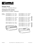
Use & Care / installation Manual
cocina
Manual de uso y cuidado /instalaci6n
Model
Modelo
233.55359591
(3o"
wide
- Stainless)
0
u
¢0
0
99043207C
Sears, Roebuck and Co,, Hoffman Estates, UL60179 U,S,A,
www,sears,com
SECTION .....................................................................
PAGE
Warranty ..............................................................................
2
Safety instructions ...............................................................
2
Operation .............................................................................
3
Cleaning ..............................................................................
3
Parts included With Hood ...................................................
4
Parts Not included With Hood ............................................
4
Tools Needed ......................................................................
4
Equivalent Duct Length Chart ............................................
5
Prepare The Hood Location ...............................................
6
Prepare The Hood ......................................................
7, 8, 9
Connect The Wiring ..........................................................
10
install The Hood ................................................................
11
Service Parts ...............................................................
12, 13
iNTENDED
WARNING
_
if within 1 year from the date of installation, any part of this
range hood fails to function properly due to a defect in material or workmanship, Sears will repair the part or furnish and
install a new part, free of charge.
FULL 30-DAY WARRANTY ON FIN_SH ON PAINTED OR
BRIGHT METAL PARTS
if within 30 days from the date of installation, the finish on any
painted or bright metal parts of this range hood is defective in
material or workmanship, Sears will furnish and install a new
part, free of charge.
WARRANTY SERVICE iS AVAILABLE BY CONTACTING
THE NEAREST SEARS SEWCE CENTER/DEPART_%'IENT
IN THE UNITED STATES.
This warranty applies only while this product is in use in the
United States. This warranty gives you specific legal rights
and you may have other rights which vary from state to state.
Sears, Roebuck and Co,, Dept 817WA, Hoffman Estates,
IL 6017
FOR DOMESTIC
WARNING
A
TO REDUCE THE RiSK OF FIRE, ELECTRIC SHOCK, OR
iNJURY TO PERSONS, OBSERVE THE FOLLOWING:
1. Use this unit only in the manner intended by the manufacturer, if you have questions, contact the manufacturer at
the address listed in the warranty.
2. Before servicing or cleaning unit, switch power off at service
panel and lock the service disconnecting means to prevent
power from being switched on accidentally. When the
service disconnecting means cannot be locked, securely
fasten a prominent warning device, such as a tag, to the
service panel.
3. Installation work and electrical wiring must be done by a
qualified person(s)in accordance with all applicable codes
and standards, including fire-rated codes and standards.
4. Sufficient
air is needed for proper combustion
and
exhausting of gases through the flue (chimney) of fuel
burning equipment to prevent backdrafting.
Follow the
heating equipment manufacturer's
guideline and safety
standards such as those published by the National Fire
Protection Association (NFPA), and the American Society
for Heating, Refrigeration and Air Conditioning Engineers
(ASHRAE), and the local code authorities.
5. When cutting or drilling into wall or ceiling, do not damage
electrical wiring and other hidden utilities.
6. To reduce the risk of fire or electric shock, do not use this
range hood with an additional speed control device.
7. Ducted fans must always be vented to the outdoors.
8. To reduce the risk of fire, use only metal ductwork.
9. Use with approved cord-connection kit only.
10.This unit must be grounded.
TO REDUCE THE RiSK OF A RANGE TOP GREASE F_RE:
1. Never leave surface units unattended at high settings.
Boilovers cause smoking and greasy spillovers that may
ignite. Heat oils slowly on low or medium settings.
2. Always turn hood ON when cooking at high heat or when
cooking flaming foods.
3. Clean ventilating fans frequently. Grease should not be
allowed to accumulate on fan or filter.
4. Use proper pan size. Always use cookware
for the size of the surface element.
COOKING
appropriate
2
_
ONLY
A
TO REDUCE THE RiSK OF iNJURY TO PERSONS iN THE
EVENT OF A RANGE TOP GREASE FIRE, OBSERVE THE
FOLLOWING:*
1. SMOTHER FLAMES with a close-fitting lid, cookie sheet,
or metal tray, then turn off the burner. BE CAREFUL TO
PREVENT BURNS. if the flames do not go out immediately,
EVACUATE AND CALL THE FiRE DEPARTMENT.
2. NEVER PiCK UPA FLAMING PAN -You may be burned.
3. DO NOT USE WATER, including wet dishcloths or towels
- a violent steam explosion will result.
4. Use an extinguisher ONLY if:
A. You know you have a Class ABC extinguisher and you
already know how to operate it.
B. The fire is small and contained in the area where it
started.
C. The fire department is being called.
D. You can fight the fire with your back to an exit.
* Based on "Kitchen Firesafety Tips" published by NFPA.
CAUTION
A
1. For general ventilating use only. Do not use to exhaust
hazardous or explosive materials and vapors.
2. To avoid motor bearing damage and noisy and/or
unbalanced impellers, keep drywall spray, construction
dust, etc. off power unit.
3. For best capture of cooking impurities, your range hood
should be mounted so that the top of the hood is 24-30"
above the cooking surface.
4. Use only with range hood cord-connection kits that have
been investigated and found acceptable for use with this
model range hood.
5. Please read specification
label on product for further
information and requirements.
hood is to be installed Non-Ducted:
Purchase a nonoducted filter from your local
distributor
or retailer and install it beneath the
aluminum
mesh filter.
[_ON
BLOWER
sPEEol
WARNING: from
To reduce
risk ofbefore
electriccleaning.
shock,
disconnect
powerthe
supply
ABuminum mesh filters
V
ON
L,GHT
Speed
Infinite speed slide control controls blower speed and sound
levels.
Blower
Turns the blower "ON" and "OFF".
When the blower is turned "OFF", the speed control remains
at the preset speed. When the b!ower is turned on again, it will
return to the previously chosen setting.
Light
Turns the light "ON" and "OFF".
Clean frequently using hot water and a mild detergent or in
your dishwasher. The aluminum mesh filters should be washed
approximately every month depending on the amount of usage. Wash more often if your cooking style generates greater
grease - like frying foods or wok cooking.
Painted hood surfaces
Wiping regularly with mild soap/detergent and warm water
should protect painted hood surfaces. Be cautious about using "New and Improved" cleaning agents. Your hood is installed over hot cooking equipment. Most chemicals found in
cleaning agents react with heat to loosen paint.
Stainless
steem hood surfaces
Stainless steel hoods should be washed regularly with a clean
cloth, warm water and mild soap or dish detergent. Clean in
the direction of the polish lines. Rinse well with clear water
and wipe dry immediately. You may wish to apply light oil used
for furniture polishing to emphasize its bright finish.
First position turns on both bulbs for normal lighting.
Second position turns off the left side bulb. If you want a nightlight feature, combine a 75 Watt bulb (on the left) and a 25
Watt bulb (on the right).
Third position turns both bulbs "OFF".
Maximum buib rating is 75 Watts. Do not install bulbs rated
higher than 75 Watts.
Bmower assembmy
Blower assembly can be cleaned with a damp cloth and mild
detergent. Use care when cleaning blower wheels - they must
not become bent or misaligned. DO NOTALLOW WATER TO
ENTER MOTOR. Make sure all surfaces are completely dry
before re-installing filters and restoring power.
Motor is permanently
motor.
lubricated.
Do not oil or disassemble
Heat Sentry TM
This hood is equipped with a Heat Sentry TMthermostat. This
device wilI turn ON or speed-up the blower if it senses excessive heat above the cooking surface.
If the blower is not ON, or if it is running at LOW speed, the
Heat Sentry TMwill override the normal blower control and turn
the blower ON to HIGH speed.
The Heat Sentry TMalso has a Iound buzzer alarm to warn you
of dangerously high temperatures on the cooking surface.
The alarm will only sound if there is a dangerous heat buildup over the range area.
IF THE ALARM SOUNDS, SHUT OFF ALL HEAT ON THE
RANGE. The alarm buzzer will sound for 1 to 5 minutes after
the heat is turned OFF and will shut off automatically (in 5
minutes or less) when the temperature under to hood returns
to normal levels.
:S
:S
O_
q_
q_
2
g3
Light Bulbs
(75 W Maximum)
(2 per hood)
Purchase locally.
Amuminum Grease Fimters
OPTmONAL PARTS (purchase separateJy)
Damper / Duct Connector
(For use with 3¼" x 10" duct)
Splashplate
Sears Part Nos.
58120
30"
Black/Bisque
58128
30"
White/Almond
58129
30"
Stainless
58130
36"
Black/Bisque
58138
36"
White/Almond
58139
36"
Stainless
58140
42"
Black/Bisque
58148
42"
White/Almond
58149
42"
Stainless
o
Parts Bag
(4 hood mounting screws inside)
Cord Kit
(Allows hood to be plugged into a
standard 120 VAC waII outlet)
Sears Part No. 233.22HCK44D
Ducting Accessories
(See "Equivalent Duct Length Chart" on page 5 for Dacting
Accessory Model Nos.
-
t'Parts Not lncmuded With Hood" available by calling Sear
[
at 1-800=4=MY=HOME _
Sacrewdriver
Q
Measure
Tape
_)
Duct
Tape
t & Phillips)
Z_
_
Wire
Stripper
i
Kenmore
rangehoodsaredesigned
toperform
efficiently
whenattached
toIongrunsofduct.Asa pointofreference,
thishood
wiIIfunction
atapproximately
80%ofitsratedairftowwhen200equivalent
feetof7"roundductwork
isattached.
Usethischart
tocalculate
theequivalent duct length of your system.
Broan Model 428
3¼-in, × 10-in,
Right-angme Embow
Equivalent length
64n. Round
Wall Cap
Equivalent
Sears
Modemlength
59691
_
34 ft.
8.5 ft.
Broan Modem 401
Straight Duct
3¼qn. × 10qn. x 2-ft, long
Equivalent length
(6-fL w/o damper)
2ft.
D
3¼oin, × 10-in.
Right=angle Fiat Elbow
Broan
_lodelIength
429
Equivalent
7=in° Round
Wall Cap
Equivalent
length
Broan
ModeB
847
24 ft.
34 ft.
(6-fL w/o damper)
Broan Modem 408
Straight Duct
8=in. round x 2-ft. long
Equivalent length
2ft°
Sears Modem
59391
3¼4n° ×
10-in,
Wamm
Cap
Equivalent
length
Broan Model 430
3¼=in, × 1Oqn,
Right=angle
Short
Eave Embow
quivalent Iength
45 ft.
15ft.
Broan Modem 407
Straight Duct
7qn. round × 2-ft° long
EquivaIent length
2ft°
6=in. Round Elbow
Broan Modem
419
EquivaIent
length
8 ft.
7qn° Round Elbow
Broan
Modem
4!5
EquivaIent
length
8 ft.
2
(7-ft= w/o damper)
Broan Model 431
3¼qn. × 10=in,
Right-angle
Long
Eave Elbow
quivaIent length
15 ft.
{b
_,lodel 59091
Roof Cap
(accepts 7-in° round
or 3¼qn° × !0-in, duct)
Equivalent length
30 ft. (7-ft= w/o damper)
Sears Modem "Ducting Accessories"
available
Sears at 1-800=4=MY=HOME _
re
by calling:
Broan Model "Ducting Accessories"
avaHabme by calling:
1=800=558=1711°
Sears Model 59581
3¼=in. × 10=in° to
6qn. Round Transition
Equivalent Iength
5.5 ft.
t_
Broan Model 412H
3¼=in, × 10-in. to
7=in. Round
Transition
Equivalent Iength
5.5 ft.
2
1. Determine whether hood will discharge vertically, horizontally, or non-ducted.
For vertical or horizontal discharge, run ductwork between
the hood location and a roof cap or wall cap.
For best results, use a minimum number of transitions and
elbows.
ROOF CAP
3W' X 10" DUCT
For vertical discharge)
HOUSE WIRING
or Back of hood)
CAP
3W' X 10" DUCT
(For horizontal discharge)
2. Use these diagrams for proper placement of ductwork and
electrical cutout in cabinet or wall.
For a nomducted
hole.
HOOD MOUNTING
SCREWS
(4)
3_A" XDUCTING
10"
l
VERTICAL
installation, DO NOT cut a duct access
3. Run house wiring between service panel and hood location.
ACCESS
(in cabinet
CENTER
L|NE
(recessed-bottom
cabinets only)
HOLE
bottom)
1
WOOD
SHIMS
3_A '' X 1 0"
(recessed-bottom
HORIZONTAL DUCTING
cabinets only)
CAB|NET
T
.OR,ZO.TALOOCT
I CABINETI BOTTOM
I
1315/16"
ACCESS HOL_
--61A
(30" hood)
I-_,--1615/16" (36"hood),
1 915/16 `' (42" hood)
HOOD
MOUNTING
SCREWS
FRONT
(4)
T
@A'.
_'_
-- T
@
431
m
1 615/16 ", (36"
(30"
hood)
_
1916/16' (42" hood)
CENTER
ELECTRICAL
ACCESS HOLE
L|NE
(in walm)
I
l
Remove and discard: _
from nose of hood,
Protective Plastic from light lens, and Cardboard FHler
from bottom of hood.
PROTECTIVE
PLASTIC --_,
Remove and set aside: Damper / Duct Connecter.
SHiPPiNG
TAPE
/
DAMPER/DUCT
CONNECTOR
CARDBOARD
FILLER
2.
Remove Bottom Cover from hood. Set cover and mounting screws aside.
:S
BOTTOM
COVER
3.
Remove Wiring Cover from hood. Set cover and mounting
screw aside.
¢e
:S
S"
WiRiNG
COVER
4. Remove either top or back Wirinq Knockout
approved Electricam Cabme Cmam£.
and install
WiRiNG
KNOCKOUT
t_
q_
q_
7
CABLE CLAMP
--
1. Choose
thecorrectblowerposition
foryourinstaIlation.
Forvertical
discharge:
MakesurethattheBmower Dis+
chargA lines up with the Duct Opening in the top of the
hood. Lift up the blower, slip the b!ower mounting rods into
brackets on blower and tighten knurled nuts securely+ Plug
in blower.
BLOWER
MOUNTING
ROD
BLOWER J
DISCHARGE
Vertical discharge
For horizontal discharge: Make sure that the Blower Dis+
charg#_ lines up with the Duct Openin_ in the top of the
hood. Lift up the blower, slip the Bmower Mounting Rods
into brackets on blower and tighten knurled nuts securely.
Plug in blower.
+ blower position
BLOWER
DISCHARGE
BLOWER
MOUNTING
ROD
¢
OPENING
Horizontal
discharge
= bmower position
2,
Remove appropriate
of hood,
Duct Knockout(s_
TOP RECTANGULAR
DUCT KNOCKOUT
(Remove for 3¼" x 10"
vertical dJsc,#arge)
from top or back
REAR RECTANGULAR
DUCT KNOCKOUT
(Remove for 3X" x 10"
horizenta! discharge)
TOP/BACK
EDGE
3= Attach 31A" × 10" Damper/Duct Connector over knockout
opening. Make sure damper Pivot is nearest to W/Back
of hood. Remove any shipping tape from damper
flap,
SHiPPiNG
TAPE
3X"x 1
DAMPER/DUCT
CONNECTOR
¢e
:S
S"
PIVOT
t_
q_
q_
2
9
HOUSE WiRiNG
(120 VAC)
WARNING: To reduce the risk of electric shock,
make sure power is switched off at the service
panel Lock or tag service panel to prevent
power from being switched on accidentally.
1. Connect House Wiring, (120 VAC) to hood. Use a piece of
Cardboard to protect the cooktop, if necessary.
A Cord Kit is available - which enables the hood to plug
into a standard 120 VAC wall outmet.
See page 4 for Cord Kit information.
Cord Kit avaimable by calling Sears
at 1-800=4_MY=HOME _
Use only with range hood cord-connection kite
that have been investigated and found acceptable for use with this modet range hood.
\
CARDBOARD
(Use to protect
cooktop)
GREEN
GROUND
SCREW
2. Connect house black to hood black wire, house white to
hood white wire, and house ground under Green Ground
Screw. Securely tighten cable clamp onto house wiring.
3. Replace wiring cover.
10
Hanghoodfrom(4)Mountin_
(frompartsbag).
Slidehoodtowards
walluntilmounting
screwsareengagedinnarrow
endof(4)_.
Tighten
mounting
screws
securely.
KEYHOLE
(4)
MOUNTING
SCREW
(4)
CAUTION:Donot pushon fiReror fan blade!
PushingonthefiRerorfanbmade
maycausethem
tointerfere
withetherhoodparts.
DUCT TAPE
DUCTWORK
2. Connect
Ductwork
to hood. Use Duct Tape to make
joints secure and air tight.
@
LIGHT LENS LEGS
3. Install 75 W Ma×imum LiehL_ht
Bulbs. Purchase bulbs locally. Gently squeeze L_qht Lens LeAs to remove and replace lens.
¢e
CAUTION: Bulbs may be hot! Refer to bulb packaging for further
3"
information.
4. Turn on power at service panel, and test for proper
operation.
75 W MAXIMUM LIGHT BULBS
5.
Replace Bottom
Cover.
6. Install filters.
Push filters up into recess at top of hood. Swing filters in
and pull down. Make sure that Tab on filter is toward outside and bottom of hood.
PULL DOWN
SWING IN
__h
PUSHIN
(_
BOTTOM
COVER
11
TAB
KEY
PART
NO. NUMBER
2
3
4
5
6
7
8
9
10
11
12
13
14
15
16
17
18
19
20
21
22
23
24
25
26
27
28
29
30
31
**
97007656
99150478
97007631
99110605
97007776
99270536
97007541
99150489
99020142
99020143
98005212
99100439
99080197
97007313
99420464
99260476
97014305
95000924
99111127
99111123
97006078
98005221
99100379
99150471
97005680
98006546
97007894
93260454
99170245
97007665
99043207
DESCRIPTION
Wiring Box Cover
8-18 x 3/8 Phillips Truss Head Screws (4 Required)*
Bottom Cover - Stainless
Light Lens
Thermostat Assembly
Bulb Holder (2 Required)
Control Board Assembly
#6B-20 PhiIlips Flat Head Screws (2 Required)*
Blower Wheel, Clockwise
Blower Wheel, Counterclockwise
Motor Retaining Ring
Rubber Vibration Ring
Motor
Blower ScrolI Housing
Blower Mounting Rod (2 Required)
Blower Mounting Rod Nut (2 Required)
Control Panel Assembly (30" Wide Hoods)
Blower Knob
Speed Control Knob
Light Switch Knob
Damper Assembly dnctudes Key Nos, 23 & 24)
Damper FIap
Damper Bushing
#10-32 x 1/2 Green Ground Screw*
Motor Receptacle with Leads
Bulb Holder Cover
Aluminum Filter Kit (Contains 2 Filters)
Sheet Metal Nuts, "U" Type (2 Required)
#8B x 3/8 Hex Head Sheet Metal Screws (13 Required)*
Wire Harness with Lamp Holders
Installation Instructions
Light Bulb, 75 Watt Max, (2 Required) (or one 75 watt and one 25 watt) Not supplied with hood,
*Standard Hardware,
** Not Illustrated,
May be purchased locally,
12
?
j"
29
jJ_
26
27
3
17
16
4
/
I
15
17
10
13
!
14
13
12
11
13
SECCK_N
................................................................
PAGINA
Si dontro do 1 aho do la focha do la instalaci6n, cualquior parto de osta
campana de cocina doja do funcionar on forma apropiada dobido a
defocto on ol material o mano do obra, Soars roparar_ la pioza afoctada
o provoorA o instalar_ una pioza nueva sin cargo.
GARANTI'A
COMPLETA DE 30 DIAS EN EL ACABADO
DE
PIEZAS PINTADAS O DE METAL LUSTROSO
Si dontro de los 30 dfas do la focha de instalaci6n, ol acabado do
cualquior pioza pintada o de metal lustroso do osta campana do
cocina prosenta dofocto do matorial o mano de obra, Sears
provoor_ o instal_ra una pioza nuova sin cargo.
EL SERVICIO DE GARANTI'A SE OBTIENE PONI_:NDOSE EN
CONTACTO
CON
EL
CENTRO
DE
SERVmCIO
O
DEPARTAMENTO SEARS M,&S CERCANO EN LOS ESTADOS
UNIDOS.
Esta garantia es vAlida unicamonte si osto producto so oncuontra
on uso dontro do los Estados Unidos. Esta garantia Io confioro
dorochos Iogalos ospocificos y Ud. puode tenor adorers otros
dorochos quo varfan do ostado a ostado.
Sears, Roebuck
L 60179
PREVJSTO
ADVERTENCIA
PARA COCJNAR
2.
3.
4.
Antes de efectuar algOn servicio o limpieza, se debe desconectar
la
corriente
el6ctrica en el armario de circuitos y asegurarlo
con Ilave
para evitar que la corriente sea conectada
accidentalmente.
Cuando
el medio de desconexi6n
del servicio no puede ser trabado, sujete
un dispositivo
de advertencia
evidente,
tal come una etiqueta,
al
panel de servicio.
do instalaci6n
y cableado electrico debe ser realizade
calificado y de acuerdo con todos los c6digos y normas
incluyendo
los c6digos
y normas
relacionados
con
clasificada
para incendio.
AI cortar o perforar la pared o el techo,
y otros servicios pOblicos ocultos.
6.
Para reducir el riesgo de incendio
esta campana con un dispositivo
7.
Los ventiladores
hacia el exterior.
8.
Para
9.
Use con
reducir
con conducto
el riesgo
PARA REDUCmR
ESTUFA:
se debe
deber_n
della
instalar
EL RIESGO
siempre
tener
use s61o conductos
conexi6n
de la cuerda
con conexi6n
a tierra.
DE UN INCENDIO
no utilice
adicional.
SOLAMENTE.
2.
Siempre
ENCIENDA
temperatura
o cuando
la campana
cuando
cocine
cocine alimentos
que se puedan
3.
Limpie con frecuencia
los ventiladores.
No debe
grasa se acumule
en el ventilador
ni en el filtro.
4.
Utilice un sarten de tama[io
adecuado.
Siempre utilice
adecuado
al tama[io
del elemento
do superficie.
permitir
3.
NO UTILICE AGUA, incluyendo
toallas de cocina
resultar una explosi6n
de vapor violenta.
4.
un extintor
SOLAMENTE
A.
Usted sabe
utilizarlo.
que tiene
B.
El incendio
inlClO,
C.
Los bomberos
D.
Usted
ESTE
EN LLAMAS
mojadas
- Usted
- puede
si:
un extintor
es peque[io
puede
QUE
y contenido
de clase
ABC
dentro
del _rea
y ya sabe
donde
se
han sido avisados.
combatir
el incendio
con una salida
a su espalda.
en la Cocina"
PRECAUCKSN
1.
Solamente
materiales
para uso general de ventilaci6n.
No utilice para descargar
peligrosos
o materiales
y vapores explosivos.
2.
Para evitar da[ios al cojinete del motor y evitar que las paletas del
ventilador emitan touche ruido o est6n fuera de equilibrio,
mantenga
el motor libre de pelusa, polvo, etc.
3.
Para obtener
mejores
resultados
en la captura de impurezas,
la
parte superior de la campana
debe estar montada de forma tal que
la campana quede de 61 a 76 cm de distancia de la superficie de la
estufa.
4.
Use s61o equipos de cable de conexi6n
para campana
cuyo uso ya se haya estudiado
y aprobado
con este
de cocina
modelo de
campana.
5.
Por favor, lea la etiqueta
de especificaciones
mayores informaciones
y requerimientos.
del
producto
para
la
el utensilio
14
Utilice
UNA SARTEN
Basado en las recomendaciones
para "Seguridad
publicadas
pot NFPA de los EE.UU.
EN LA
que
_,
NUNCA LEVANTE
se podra quemar.
solamente.
con alta
incendiar.
_
2.
de metal.
Nunca deje las unidades
de superficie
sin supervisi6n
cuando
tengan
ajustes
altos.
Los reboses
pueden
provocar
humo y
derrames
grasosos
que se pueden incendiar.
Caliente lentamente
el aceite en un ajuste bajo o medio.
Estates,
APAGUE LAS LLAMAS con una tapa ajustada, plancha para galletitas
o charola decorativa
y luego apague la hornilla. TENGA CUIDADO
DE EVITAR QUEMADURAS,
Si las llamas no se apagan de inmediato,
EVACUE
EL LUGAR
Y LLAME
AL DEPARTAMENTO
DE
BOMBEROS.
una salida
POR GRASA
Hoffman
1.
el6ctrico
o de descarga el6ctrica,
de control de velocidad
de incendio,
el kit aprobado
10. Esta unidad
no da[ie el cableado
817WA,
PARA REDUCIR
EL RIESGO DE LESIONES
A PERSONAS
EN
CASO DE INCENDIO
DE GRASA EN LA ESTUFA, OBSERVE
LO
SIGUIENTE:*
Aire suficiente
es necesario para facilitar la combusti6n
adecuada
y
la salida apropiada
de gases per la chimenea
de la unidad y para
evitar corrientes
de aire invertidas. Siga las instrucciones
y medidas
de seguridad
del fabricante
del equipo
y de las sociedades
profesionales
de equipos
do calentadores
y los reglamentos
de
seguridad
locales.
5.
1.
ELC:CTRICO,
Utilice esta unidad s61o en la manera prescrita per el fabricante.
Si
tiene usted alguna pregunta,
comuniqOese
con el fabricante
a la
direcci6n
o al t61efono indicados
en la garantia.
Todo trabajo
por personal
pertinentes,
construcci6n
DOMESTJCO
ADVERTENCmA
_, _,
PARA REDUCIR EL RIESGO DE INCENDmO, CNOQUE
O LESK}N
A PERSONAS,
OBSERVE
LO SmGUIENTE:
1.
and Co., Dept
Si se instaiara
la campana
en un sistema
sin conductos:
Compre
un filtro sin conducto
coe su distribuidor
o minorosta,
e instale{o
debajo
de{ filtro
de aluminio.
_ON
BLOWER
sPEEol
I""
ADVERTENCIA:
Para
reducir eJ riesgo
de una
descarga
et_ctrica,
desconecte
el suministro
et_ctrico antes de timpiar ta unidad.
F{mtros de maria de aBuminio
Limpie frecuentemente
los filtros con agua caliente y un
detergente suave= Los filtros se pueden lavar en lavaplatos.
Se debe
lavar
los filtros
de maIIa de aluminio
aproximadamente cada rues, dependiendo de su use. LAvelos
con mayor frecuencia si su forma de cocinar genera m4s
grasa _ come, pot ejemplo, frituras o 'wok'=
Velocidad (Speed)
El control de velocidad infinita controla
ventilador y los niveles de sonido.
Ventilador
"ENCENDE"
la velocidad
del
(Btower)
(ON) y "APAGA" (OFF) el ventilador.
Cuando el ventilador
se "APAGA" (OFF), el control de
velocidad permanece en la velocidad presente. Cuando el
ventiIador
se vuetve a encender,
regresarb, al ajuste
previamente escogido.
Luz (Light)
"ENCENDE"
(ON) y "APAGA" (OFF) Ia Iuz.
La primera posici6n enciende
normal.
ambos bulbos para una luz
La segunda posici6n apaga el buIbo de! lade izquierdo. En
case de que usted quiera una caractedstica de luz noctuma,
combine un buJbo de 75 Watts (izquierda) y un bulbo de 25
Watts (derecha).
La tercera posJci6n apaga ambos bulbos.
El valor m4ximo para el bulbo es de 75 Watts= No instaIe
buIbos con un valor mayor a 75 Watts=
Heat Sentry TM
Superficies
pintadas
de macampana
Limpiarlas
peri6dicamente
con agua tibia y un jab6n/
detergente suave protegerA Ins superficies pintadas de Ia
campana. Tenga cuidado si usa agentes de Iimpieza "Nuevos
y Mejorados'L Su campana est_ instalada sobre equipos de
cocina calientes. La mayor[a de los productos qu[micos que
contienen los agentes de Iimpieza calentaran y afiojaran la
pintura.
Superficies de acero inoxidabte de la campana
Se debe Iavar Ins campanas
de acero inoxidable
peri6dicamente con un paho limpio, agua tibia y un iab6n o
detergente para platos suave= Limpielas en la direcci6n de
ins Ifneas de pulido. Enju_guelas bien con agua limpia y
sequeia de inmediato con un paso. Podra aplicarles un aceite
leve utilizado para lustrar muebles para realzar su acabado
lustroso.
Montaje demventilador
Se puede timpiar el ventitador con un pa_o humedo y un
detergente suave= Tenga cuidado cuando limpie Ins paletas
del ventilador - se podr[an doblar o desalinear. NO PERMITA
LA ENTRADA DE AGUA EN EL MOTOR. AsegOrese de que
todas las superficies esten completamente secas antes de
velvet a coIocar los filtros y conectar la energia electrica=
El motor estA permanentemente
desmonte el motor=
lubricado= No lubrique
ni
Esta campana esta equipada con un termostato Heat Sentry TN.
Este dispositivo ENCENDERA (ON) o acelerar& la velocidad
deI ventilador en el caso de que sienta un exceso de calor
sobre la superficie donde se esta cocinando.
Si el ventilador
no estb. ENCENDIDO
(ON), o siesta
funcionando en BAJA (LOW) velocidad, el Heat Sentry rM
sustituira !o control normal del ventilador y ENCENDERA (ON)
el ventilador en velocidad ALTA (HIGH)=
El Heat Sentry rM tambien cuenta con una alarma para
advertirte a usted de temperaturas gravemente elevadas sobre
la superficie
en Ia cuaI se estA cocinando.
La alarma
solamente sonarb, si detecta una acumulaci6n
de calor
peligrosa sobre el Area de la estufa.
O,
EN CASO DE QUE SUENE LAALARMA, APAGUE TODO EL
CALOR SOBRE LA ESTUFA. La alarma sonata durante 1 a 5
minutos despues de que se APAGO (OFF) la estufa y dejar_i
de sonar automaticamente (despues de 5 minutos o menos)
cuando la temperatura de la estufa regrese a niveles normales.
N
{n
{b
{3
15
F{mtres
degrasadealuminie
l_aximo
75de
'7,/)
BombiHas
luz
per campana)
Adquieralas IocaImente=
PIEZAS
OPTATmVAS (compra separada)
Conector
deregumador
de
tiro/conducto
(Parausocon un ductode
8.3x25.4cm[3¼"x10"])
Placa posteiror
Piezas Sears Nos.
58120
30"
Negro/Bisque
58128
30"
Blanco/
AImendra
58129
30"
Hnoxidable
58130
36"
Negro/Bisque
58138
36"
Blanco/
AImendra
58139
36"
Hnoxidable
58140
42"
Negro/Bisque
58148
42"
Blanco/
AImendra
58149
42"
Hnoxidable
o
(4tornilIos
demontaje
Bomsa
depiezas
delacampana,
adentro
Kit de cabme
(Permite que se enchufe la
campana en una toma de pared
estandar de 120 VCA)
Pieza Sears No. 233.22HCK44D
Accesorios para conductos
(Yea el "Cuadro de largo equivalente de conducto" de la
pagina 17 para obtener los Nos. de Modelos de Accesorios
para Conductos.
Las "PiezasHamando
no inctuidas
con alBacampana"
estan _
disponibmes
a Sears
1-800=4oMY=HOME
/
/
DestorniHador
(chato y PhiUips)
Q
Lapiz
Sierra
de
punta
-o-
Cinta rnetrica
Serrucho
de punta
16
Cinta
adhesiva para
conductos
/
1/4"
Ajustador
de tuercas
Pemador de
cabme
l
|
Las campanas de cocina Kenmore fueron disehadas para su desempef_o ÷ficiente cuando se las suieta a largos recorridos de conducto,
Como punto de referencia, esta campana funcionara a aproximadamente et 80% de su fluio de aire nominal cuando se le sujeta 81 m (200 pies)
equivalentes de conducto redondo de 17,8 cm (7"), Utilice esta cuadro para calcular e! largo equivalente de conducto de su sistema,
Modelo Sears 59691
8-pulg. TapSn de
pared redendo
Largo equivaIente
Modelo Broan 428
Acodado con angumo
a la derecha
3_A-pumg,x
10-pulg.
Largo equivaiente
10 m (34 pies)
(1,8 m [6-pies] sin
regalador de tire)
2.6 m (8.5 pies)
Modelo Broan 401
Conducto recto
3%-pulg. x 1O-pulg, × 2-pies de largo
Largo equivalente
Modeto Broan 429
31A-pulg. x 1O-puBg.
Acodado piano con
angumo ama derecha
Largo equivalente
0.81 m (2 pies)
7.3 m (24 pies)
Modeio Broan 406
Conducto recto
6-pumg, alrededor x 2 pies de largo
Largo eqaivalente
0.81 m (2 pies)
_
3%-pulg. x 10-pumg,
Acodado
con amero corto
y angulo ama
derecha
Modemo
Broan 430
Largo equivalente
4.6 m (15 pies)
ModeBo Broan 847
(_
pared
redondo
Largo
7_pumg.TapTn
equivalente
de
10 m (34 pies)
(1,8 m [6-pies] sin
regulador de tiro)
ModeBo Sears
59391
3_A-pumg.x
10-pumg,
p6n de pared
go eqaivalente
14 m (45 pies)
(2,1 m [7-pies] sin
regulador de tiro)
Modelo Broan 407
Conducto recto
7-pumg. airededor × 2 pies de margo
Largo equivalente
0.81
Modelo Broan 431
3_A-puBg.x 1O-puig.
Acodado
con alero Bargo
y _ngulo a Ba
derecha
argo equivalente
rn (2 pies)
Acodado redondo
Modemo
de 6Broan
pumg. 419
Largo equivalente
.6 m (15 pies)
2.4 m (8 pies)
Sears 59091
Tap6n de techo
(acepta ducto de
7-pulg, redondo o
de 3_A-pumg.x 1O-puBg,)
Largo equivalente
N
9.1 m (30 pies)
(2,1 m [7-pies] sin
regulador de tiro)
Modemo Broan 415
Acodado redondo
de 7 puBg.
Largo equivalente
2.4 m (8 pies)
Los "Accesorios
para los conductos"
Modemo Sears estan disponibmes
Hamando a Sears al 1-SOO-4-MY-HOME _
Los "Accesorios
para conductos"
Modelo Broan estan disponibles
Hamando a}: 1-800-558-1711.
Mode_o Sears 59581
31A-pumg.x 1O-pulg.
a 6-puWg.
Transici6n redondo
Largo equivalente
1.7 m (5.5 pies)
N
Modelo Broan 412H
31A-pumg,x 1O-pulg.
a 7-pumg,
TransiciTn redondo
Largo equivaIente
1.7 m (5.5 pies)
17
1. Determine si la descarga
horizontaI o sin conducto.
de Ia campana
ser_ vertical,
TAPADETECHO
CONDUCTODE
8,3 cm x 25.4 cm
En el case de descarga vertical u horizontal, tienda los
conductos entre e! Iugar donde se instaIara la campana y
el tap6n de techo o el tap6n de pared.
(Para
descarga
vertical)
Para obtener Ios mejores resuItados, utilice una cantidad
mfnima de transiciones y codes.
CABLEADO
ELECTRICO
LA CASA
(Parte superior
de la campana)
_TAPON
t
45.7 cm a 60.9 cm
3. Gu[e Ias conexiones deI cableado de la casa entre el
panel de servicio y el lugar deride instalara la campana.
TORNILLOS PARA MONTAJE
CONDUCTOS DE
I 8.3
SISTEMA
VERTICAL
DE LA CAMPANA (4)
cra × 25.4
cra (3W' xDE
10") 1
35.4
cm
(campal_a
43.0
cm
(ca mpa_a de 914
de 762
)ana de 1067
FRENTE
ore)
_
35.4
43,0
ore)
50.6
cm
(carnpana
cra
(caFYipana de 91 4 cm_,_
cm
(oampalla
de 762
ore)
de 10(>7 cm)
DEL GABINETE
ORIFICIalDEACCESOt
CU!_AS DE MADERA
PARA CABLES ELE_CTRICOS
(s61ogabinetes con CENTRAL (en la base del gabinete)
base empotrada)
CUNAS
DE MADERA
(s61o gabinetes con
base empotrada)
TORNILLOS
MONTAJE
CAMPANA
18
DE PARED
CONDUCTO
DE
8,3 cmx 25.4 cm
(Para descarge horizontal)
SOBRE LA SUPERFICE
PARACONCINAR
2. Utilice estos diagramas para colocar adecuadamente los
conductos y hacer el corte exacto para la conexi6n electrica
en el gabinete o en la pared.
En el case de aquellas instalaciones
en sistemas sin
conductos, NO haga ningOn orificio de acceso para el
conducto.
o posterior
PARA
DE LA
(4)
I SISTEMA HORIZONTAL DE
CONDUCTOS DE
I 8.3 cm × 25.4 cm (3W' x 10")
t
M'NEA
CENTRAL
ORIFICIO DE ACCESO
PARA CABLES ELE2CTRICOS
(en la pared)
Retire
y deseche:
Lacinta de embalaie de Ia nariz de la
campana, el pmastico de protecci6n
del Iente de Iuz y el
relleno de cart6n de la parte inferior de la campana.
Retire y fije aparte: Conector
de regumador de tiro/
conducto.
PL,_STICO DE
PROTECCION
8
CINTA DE
EMBALAJE
CONECTOR DE
REGULADOR DE
TIRO/CONDUCTO
RELLENO DE
CARTON
Ca
2. Retire la cubierta inferior de Ia campana. Coloque la tapa
y los torniilos de montaje a un lade.
O,
CUBIERTA
iNFERiOR
3. Quite Ia _a
demcabBeado del interior de Ia campana.
Coloque la tapa y el tornillo de montaje a un lade.
SS
N
TAPA DEL
CABLEADO
4. Quite eI
para los cabmes electricos, ya
sea e! superior o el posterior, e instab una grapa para
cable eiectrico aprobada.
AGUJERO CIEGC
PARA LOS CABLES
ELE_CTRICOS
X_
N
{a
{b
19
GRAPA PARA
CABLE ELE_CTRICO
1. EscojaIa posici6ncorrectadel ventiladorparasu
instalaci6n.
ABERTURA DEL
DUCTO
Paraunadescarga
verticaE:
Aseg0rese
dequeladescarga
dem
ventHador
estealineada
conIaabertura deBducto en
la parte superior de la campana. Levante eI ventilador,
deslice Ias barras de montaje deI ventilador dentro de las
escuadras
en el ventilador
y apriete
las tuercas
firmemente. Conecte el ventilador.
BARRA DE
MONTAJ E DEL
VENTILADOR
J
DESCARGA
DEL
VENTHLADOR
Descarga
Para una descarga horizontal:
Aseg8rese de que la
descarga del ventilador
este alineada con la abertura
del ducto en Ia parte superior de Is campana. Levante el
ventilador, deslice las barras de montaje de_ ventilador
dentro de Ias escuadras en e! ventilador y apriete las
tuercas firmemente. Conecte el ventilador.
verticam =posici6n
DESCARGA DEL
VENTHLADOR
BARRA DE
MONTAJE
DEL
¢
1
1
Descarga horizontal
2O
demventilador
"1
!
= posici6n
del ventilador
AGUJERO
CHEGO DEL
CONDUCTO
RECTANGULAR
SUPERIOR
2. Quiteel
paralosconductos
apropiados
delapartesuperior
odelaparteposterior
de
lacampana.
(Quite para descailga
de 8.3x25.4
cm [3X"
8
verticai
x 10"])
Ca
AGUJERO CHEGO DEL
CONDUCTO RECTANGULAR
POSTERIOR
(Quite para descarga horizontai de
8,3x25,4 cm [3X" x 10"])
3. Coloque et conector del reguBador de firo/conducto de
8,3 x 25.4 cm (314" x 10") sobre Haabertura de! agujero
ciego. AsegOrese de que el pivote dell regulador de tire
quede Io mas cerca posibb del borde superior/posterior
de Hacampana. Quite la cinta de embabje de la abta del
regulador de tire.
BORDE
SUPERIOR/
POSTERIOR
CHNTA DE
EMBALAJE
2
Ca
O,
pCONECTOR DE
REGULADOR DE TIRO/
CONDUCTO DE
8.3 x 25.4 cm (3X" x 10")
SS
N
PHVOTE
X_
N
q_
21
ADVEFtTENCIA:
Para reducir eJ riesgo de
descargas eJ_ctrica$, asegQrese de apagar eJ
interruptor
de alimentaci6n
el_ctrica en e!
panel de servicio. BJoquee o _otule el paneJ
de servicio para evitar que aiguien conecte
accidentaJmente ta energ{a electrica.
CABLEADO
DE LA CASA
1. Conecte el cableado de la casa (120 VCA) a la campana.
Si fuera necesario, use un pedazo de cart6n para proteger
la superficie de la estufa.
Hay un Kit de Cable disponibie, que permite que se
enchufe la campana en una toma de pared estandar
120 VCA.
de
Use $61o equipos de cable de cone×i6n para
campana de cocina cuyo uso ya $e haya
estudiado y aprobado con este modeto de
campana.
CARTON
(Usar para proteger la
superficie de la estufa)
TORNILLO VERDE DE
CONEXION A TERRA
2. Conecte e! cable negro de! suministro de Ia casa al cabIe
negro de la campana, el cable bIanco deI suministro de Ia
casa aI cabte blanco de Ia campana y la conexi6n a tierra
de{ suministro domestico debajo del tomiHo verde de
conexi6n a tierra. Ajuste bien Ia grapa para cable el6ctrico
aI cableado de Ia casa.
3. Vueiva a instalar la tapa de la conexi6n eJ6ctrica.
22
ORIFICIO
TIPO
Cueigue
Iacampana
deIos(4)tomiHos
demontajA
(que BOCALLAVE
(4)
seencuentran
enIabotsadepiezas).
Deslice
lacampana
hacialaparedhastaqueIostornillos
demontaje
queden .....
conectados
ene!extreme
angosto
delos(4)odficioe tipo
boeaHave.
TORNILLO DE MONTAJE (4)
8
Apriete fijamente los tornillos de montaje.
PRECAUCK_N: iNo presione sobre Ba paleta deB
ventilador!
El empujar la paleta puede hacerma
interferir con otras piezas de maeampana,
¢#
2. Conecte eI eistema de conductos
a Ia campana. Use
cinta para conductos para fijar y sellar las uniones
hermeticamente.
CINTA PARA
CONDUCTOS
SISTEMA DE CONDUCTOS
O,
PATAS DE LA LENTE DE LUZ
3. Instale bombillas con un valor maximo de 75W. Compre
la bombilla Iocalmente. Apriete Ias patas de la Bente de
muzsuavemente para retirar y reemplazar la bnte.
p-
PRECAUC_ON: iLas bombillas de luz pueden set
camientes! Consulte emembalaie de las bombiHas
informacion adicionaL
N
4. Conecte la energ[a en eI panel de servicio y revise el
funcionamiento adecuado de la campana.
BOMBILLAS CON UN VALOR M,&XIMO DE 75 W
5. Vuelva a colocar la cubierta
6.
inferior.
Instab Ios filtros.
Empuje Ios filtros hacia arriba dentro del hueco en
la parte superior de la campana. Balancee los filtros
hacia adentro y jab hacia abajo. AsegOrese de que
la etiqueta en eI filtro se encuentra hacia afuera y
hacia la parte inferior de la campana.
JALE HACIA
ABAJO
X_
(-{_
N
CUBIERTA
iNFERiOR
q)
EMPUJE HACIA ADENTRO(_
23
ETIQUETA
CLAVE
NO.
2
3
4
5
6
7
8
9
10
11
12
13
14
15
16
17
18
19
20
21
22
23
24
25
26
27
28
29
30
31
**
PmEZA
NO.
97007656
99150478
97007631
99110605
99270536
99270536
97007541
99150489
99020142
99020143
98005212
99100439
99080197
97007313
99420464
99260476
97014305
95000924
99111127
99111123
97006078
98005221
99100379
99150471
97005680
98006546
97007894
93260454
99170245
97007682
99043206
DESCRmPCmON
Cubierta de la caja de cables
TorniJlo met_lico Phillips para chapa metalJca de enrejado de 8-18 x 3/8 (se necesitan 4)*
Cubierta inferior - acero inoxidable
Lente de Iuz
Montaje del termostato
Sostenedor de Ia Iampara (se necesitan 2)
Montaje del tablero de control
TornilIos de cabeza plana No. 6B-20 Phillips (se necesitan 2)*
Rueda del ventilador, en sentJdo de Ias manecilJas de! reloj
Rueda del ventilador, en sentido contrario a Ias maneciJlas del reloj
Anillo para detener el motor (se necesitan 2)
Anil!o de vibraci6n de caucho
Motor
Tapa de! ventilador
Barra de montaje deI ventilador (se necesitan 2)
Tuerca de Ia barra de montaje del ventJlador (se necesitan 2)
Montaje del tablero de control (Campanas de 30" de ancho)
Bot6n del ventilador
Bot6n del control de velocidad
Bot6n deI Hnterruptor de luz
Unidad de! regulador (Hnctuye Claves Nos. 22 & 23)
Aleta del regulador de tire
ManguilIo deI reguJador de tire (se necesitan 2)
TornilIo verde de conexi6n a tierra No. 10-32 x 1/2"
Receptaculo del motor con cables
Cubierta del sostenedor de la bombilIa
Equlpo del filtro de aluminio (contiene 2 filtros)
Tuercas para tamina, tipo "U" (se necesitan 2)
TornilIos para lamina No. 8B x 3/8 con cabeza hexagonal (se necesitan 13)*
Arn6ses para el cableado con sostenedores de Ia 15mpara
Hnstrucciones para Ia instalaci6n
BombilIa de luz, 75 Watt M_x. (se necesitan 2) (o una de 75 watts y una de 25 watts) No se
suministran con la campana.
* Herrajes estandar - pueden comprarse
Jocalmente.
** No ilustrado.
24
32
(3
25
2?
N
3
4
(n
O,
13
12
25
26
27
iiiiiiiiiiiiiiiiiiiiiu_
.....
HHHHHHHHHH
_
iiiiiiiiiiiiiiii
_
iiiiiiiiiiiiiiii
iiiiiiiiiiiiiiii
iiiiiiiiiiiiiiii
iiiiiiiiiiiiiiii
iiiiiiiiiiiiiiii
iiiiiiiiiiiiiiii
iiiiiiiiiiiiiiii
iiiiiiiiiiiiiiii
iiiiiiiiiiiiiiii
iiiiiiiiiiiiiiii
iiiiiiiiiiiiiiii
iiiiiiiiiiiiiiii
Your Home
For repair-in
your home-of
all major brand appliances,
lawn and garden equipment, or heating and cooling systems,
no matter who made it, no matter who sold it!
For the replacement parts, accessories and
owner's manuals that you need to do-it-yourself.
For Sears professional installation of home appliances
and items like garage door openers and water heaters.
I oS00o4oMyoHOME ®
(1-800-469-4663)
Ca,aoyt_e,
dayorn_ght/U.S.A,
aodCaoada!
www.sears.oomwww.sears.oa
iiiiiiiiiiiiiiii
Forrepair
ofcarry-in
_tems
likevacuums,
lawnequipment,
and electronics,
call or go on-line for the location of your nearest
Sears 1?rts
Repair
800 t488
1222Center.
Call anytime,
day or night (U.S.A.
only)
www.sears.com
To purchase
or maintenance
a protection
agreement
(Canada)ona
1-800-827-66ss
Para pedir servicio
a domicilio,
de reparaci6n
y para ordenar
1-888-SU-HOGAR
(1-888-784o6427)
piezas:
sM
agreement
(U.S.A.)
product serviced
by Sears:
1-800-361-866s
o oo0o
Au Canada
pour service
en fran(_ais:
1.800.LE.FOYEF{MO
(1°800°533°6937)
www.sears.ca
® Registered Trademark / TM Trademark / SM Service Mark of Sears, Roebuck and Co.
® Marca Registrada / TM Marca de F_brica / SM Marca de Servicio de Sears, Roebuck and Co.
MCMarque de commerce / _4DMarque d@pos6e de Sears, Roebuck _d Co.
© Sears, Roebuck and Co.
iiiiiiii