1
-m
®
FOOD WASTE DISPOSERS
installation,
TOOLS
AND MATERIALS
Slotted Screwdriver,
Electrical Tape
Adjustable
TOOLS, MATERIALS,
YOU MAY NEED:
Care & Use Manual
YOU WILL NEED:
Pliers,
Plumber's
Read through the entire Installation,
Care
& Use manual before installing the disposer. Determine
which of the tools,
materials,
and accessories
you will need
before you begin. Make sure you have all
necessary
disposer
parts before install-
Putty,
AND ACCESSORIES
ing the disposer
diagram below).
Phillips Screwdriver,
Drain Auger, 3/8" Electrical Clamp
Connector,
Wire Nuts (2), Second 1 1/2" Drain Trap,
Hammer,
Hacksaw, Water Hose Clamp, Pipe Wrench,
Copper Ground Wire, Dishwasher
Drain Connection
Kit, Air
Gap, Electrical On/Off Switch, Drain Tube Extension
(see part identification
1
(_)1&
#1
Otc
d
00
N
K
OR
#2
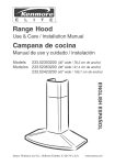
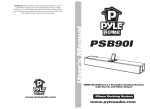
Mounting
Assembly
Disposer
A Stopper
B Sink Flange
C F_ber Gasket
H Mounting Gasket/Splash
I Lower Mounting Ring
J D_shwasher Inlet
D.
E.
F
G
K D_scharge Outlet
L' Wrenchette
Backup Rmg
Mounting
Ring
Screws (3)
Snap Ring
Discharge
Assembly
#1
M Nut
Baffle
#1
N. Beveled DLscharge Tube
(1-1/2" Dlam )
O. Beveled Washer
P. Flanged
Gasket
OR
--
Discharge
Assembly
#2
M. Bolt
#2
SAFETY
N. Discharge
O Flange
P Gasket
Tube (1-1/2"
Diarn )
SYMBOLS
Danger indicates an
imminently hazardous situation which,
if not avoided, wdl result m death or
senous injury
I'_k WARNING I Warning indicates
a potentrally hazardous s_tuation
which, if not avoided, could result m
death or serious injury
[',_gCAUTIONI Caution indicates a
potentially hazardous situation which,
if not avoided, may result m minor or
moderate mjury
72785
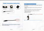
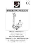
CHECK
INSTALLATION
DIMENSIONS
1odel
A. Disposer Height
B. Distance from bottom of sink
]
B
bowl to centerline of discharge
outlet. (Add 1/2" when stainless
steel sink is used.)
A,
C: Distance from centerline of
the discharge outlet to end
of discharge tube.
D: D_sposer Width
D ---'-----E: Distance from disposer vertical
centerline to centerline of
P-trap connection.
F: Centerline of disposer discharge to centerline at waste pipe entering wall.
(Dimension "F" must be greater than 1/4" to prevent standing water in disposer.)
L
If replacing an existing disposer, skip ahead to Instruction 6.
If this is a first time installation, continue with Instruction
2.
DISCONNECT
]
/
B
C
b
E
010/6012 11 3/8"
A
6"
4"
6 5/16"
5"
01116013 12 5/8"
6"
4"
6 5/16"
5"
0552
6"
4"
7 1/4"
5"
12 5/8"
5/8'--6,' 4,' 71/4,' 5"
_3/4"
611/16" 4'=._
_ 81/2'.=_=___'
53/4'_
3/4"
0559*
--
_1157/8"
"
6 11/16" 4"
8 1/2"
5 3/4"
9 7/16"
6"
4"
4"
7 1/2"
7 1/4"
5 3/4"
5"
6"
4"
7 1/4"
5"
_'" Indicates Batch Feed Model
SINK DRAIN
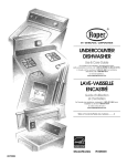
1. Loosen nut (A) at top of "P-trap" with pipe wrench (see Figure 2-1).
2. Loosen nut (B) at top of extension pipe. Remove extension pipe.
3. Loosen nut (C) at base of sink flange. (If nut is corroded or too tight, apply
penetrating lubricant
4. Push s_nk flange up through sink hole and remove it (see Figure 2-2).
5. Clean sink flange area of any putty or other debris.
J
"
DISASSEMBLE
NEW DISPOSER
MOUNTING
ASSEMBLY
-
r
"
2-1
1. Insert wrenchette (or screwdriver) into one mounting lug and hold lower mounting ring securely with one hand (see Figure 3-1). With your other hand, turn
mounting assembly counterclockwise to remove mounting assembly from lower
mounting ring
2. Turn mounting assembly over (see Figure 3-2) and loosen three mounting
screws (A) until you can access snap ring (B).
3 Use screwdriver to pry snap ring off of sink flange. Mounting assembly will
now come apart.
INSTALL
FLANGE
/_
IN SINK HOLE
2-2
/
!i
3-1
3-2
4-1
4-2
Roll 1/4 pound (4 oz.) of non-hardening plumber's putty to make 3/4" thick rope
to seal around sink flange.
2. Apply putty evenly around sink hole (see Figure 4-1).
3. Press sink flange slowly but firmly into sink drain hole to seat evenly on putty
(see Figure 4-2). Use screwdriver or putty knife to scrape all putty from edge
of sink hole.
1.
_k CAUTION
Do not use plumber's putty on any other disposer connection - it
may harm disposer and cause property damage.
ATTACH
UPPER
MOUNTING
ASSEMBLYTO
SINK FLANGE
You may wish to place a we=ghted object in the sink to hold the sink flange in place. (Place a towel
under object in sink to prevent scratching ) Reference F=gure 5-1 for part identification.
1 Working from under sink, slip fiber gasket and 4 Tighten three mounting screws up to sink
metal backup ring over sink flange.
until mounting assembly is seated tightly
2 Holding fiber gasket and backup ring in place,
and evenly against sink.
shp mounhng nng over s_nk flange so it seats
* Placing a thick, wide rubber band around
against backup nng
the sink flange (above the snap ring
3 W_th fiber gasket, backup nng, and mounting
groove) may help hold parts Jnplace _,,hde
ring hght to S,F.'.__ottom, shde snap r',ng cnto
tnstalhng snap ring. (Remember to rer'nove
rubber band after snap ring is installed.) '
s_nk flange until _tpops {nto groove on flange'.
If you are replacing an existing disposer, go to Instruction
skip ahead Io Instruction
7
6 If this is a first time _nstallahon, 1
J
Sink Flange
Fiber Gasket
Backup
/
R=ng __
_._'_).
MountEng RLng __
Snap Ring
X_-@
O
5-1
REMOVE
EXISTING
DISPOSER
1. Turn off electrical power at fuse box or circuit breaker.
Electric
o Turn off electrical power at fuse
box or circuit breaker before
removing electrical cover plate,
Shock
,, Disposer must be grounded.
Improper connection can
result in electric shock.
i
L
WARNING
6-1
6=2
Personal Injury
o Do not position your head or body under disposer; unit could fall
dunng removal or installatton.
2. Disconnect drain trap from disposer waste discharge tube with adjustable pliers
(see Fig. 6-1 ). (Also disconnect dishwasher drain connection, if required.)
3. Support disposer with one hand and insert end of wrenchette or screwdriver
into right side of one mounting lug on lower mounting ring (see Figure 6-2).
Lift disposer slightly and loosen lower mounting ring by pushing or pulling
wrenchette or screwdriver to left until disposer is free from mounting assembly.
(Disposer may be heavy - provide support.)
4. W_th electrical supply turned off, turn disposer upside down and remove electrical cover plate (see Figure 6-3). Loosen green ground screw and remove
wire nuts (see Figure 6-4). Disconnect disposer wires from electrical supply
wires. Loosen screw(s) on electrical clamp connector and remove wires from
6-3
ofthenew
stsame
he
as
odone
removemo
isposerm
I 1I
disposer,
j
from disposer (Instruction
3) and go to Instruction
7.
o If the new disposer mounting is different from the old one (or you wish to replace
the old sink flange) you must complete Steps 5 - 6 (below), and Instructions
25, then continue with Instruction
7.
6-5
--
5
Loosen three mounting screws, pry snap ring off with screwdriver, and remove
old mounting assembly (see Figure 6-5). (Some mounting assembly removal
requires addittonal tools.)
6. Push old s_nk flange up through sink hole (see Figure 6-6). Use screwdriver or
putty knife to scrape all old putty from edge of sink hole.
CLEAN
SINK DRAIN
LINE
Failure to clean sink drain line may result in drain line blockage.
1. Remove P-trap.
2. With drain auger, clear all hardened waste material in horizontal
I If you are not connecting
a dishwasher to disposer, go to Instruction
PREPARE
DRAIN
DISHWASHER
APPLICABLE)
drain line.
CONNECTION
9.
II
(IF
The knockout drain plug should only be removed if you are connecting
a built-in dishwasher to the disposer. NOTE: If the dishwasher
connection is made without removing the plug, the dishwasher may
overflow. (Connections must comply with local plumbing codes.)
Remove Knockout Plug
1. Lay disposer on its side and insert screwdriver into dishwasher inlet so tip rests
on outer edge of knockout plug
2 Tap end of screwdraver handle with hammer until molded plug breaks loose
(see Figure 8-1)
3 REMOVE LOOSE KNOCKOUT PLUG FROM INSIDE DISPOSER.
Attach Dishwasher
Drain Connector
If your d_shwasher drain hose ts 7/8" d_ameter, go to Instruction
9.
If your d_shwasher dra=n hose rs not 7/8" diameter, you must attach a dishwasher
drain connector to the dishwasher drain inlet Follow the fnstallation instruct_ons
wrth the cnnn_r'tl_n kit (Yr_tJwtll r'c_nn_r't th_ dishwasher drain h,_se to the
8ol
CONNECT
DISPOSER
TO ELECTRICAL
SUPPLY
Electric
Shock
o Do not attach ground wire to gas supply pipe.
o Disconnect power before installing or servicing disposer.
* If three-prong, grounded plug is used, plug must be
inserted into three-hole, grounded receptacle.
,, All wiring must comply with local electrical codes.
o Do not reconnect electrical current at main service
panel until proper grounds are installed.
o Improper connection of the equipment-grounding
conductor can result in a risk of electric shock.
Check with a qualified electrician or serviceman if
you are in doubt as to whether the appliance is
properly grounded. Do not modify the plug provided
with the appliance - if it will not fit the outlet, have a
proper outlet installed by a qualified electrician.
o This disposer must be properly grounded.
There are two ways to connect electrical power to your disposer:
1.) Direct wire
2.) Plug in cord - installed at factory, or from Kenmore Kit #60686 (for all models listed in this manual)
Disposer Circuit Requirements
Ensure the following electrical requirements
wired electrical circuit diagram):
•
o
w
are met before connecting disposer to switch (see Figure 9-1 for typical direct
Remove fuse (or open the circuit breaker) before connecting
d_sposer to circuit.
Batch feed disposers do not require a separate wall switch
- switch is built into disposer and disposer is wired directly
into circuit.
If junction box is used, connect the junction box to the switch
on a separate 15 or 20 Amp, 115 Volt c_rcuit with the appropriate cable. (Use 14 gauge wire with 15 Amp circuit, and 12
gauge wire with 20 Amp circuit).
°
°
If you install a double receptacle to handle other small kitchen
appliances, include a wall switch in disposer receptacle c_rcuit
and wire other receptacle directly to power source.
This d_sposer requires a switch with a marked "Off" position
(wired to disconnect all ungrounded supply conductors)
installed within sight of the disposer sink opening (1 HP minimum rating).
Connect Disposer to Electrical Supply/Ground
Disposer
Follow these instructions to direct wire the disposer. (if adding a cord and plug, follow
the directions included with the cord and plug).
1 Remove electrical cover plate from bottom of disposer and pull out black and white
wires (see Figure 9-1). DO NOT REMOVE CARDBOARD INSULATION SHIELD.
2 Run electrical cable through access hole (A) on bo[tom ot cihsposer/w_[n 1/2"
conduit or 3/8" flex) and secure with clamp connector.
3. Strip wTres back approximately 1/2 inch. Connect white (neutral)
electrical wire to white disposer wire, and black (hot) electrical wire to black
disposer wire (may have colored stripe) with wire nuts (see Figure 9-1). Insulate
wire connections with electrical tape, and push connections into disposer housing
without displacing cardboard insulation shield. Do not reinstall electrical plate until
disposer is properly grourded.
Once the circuit you are using is grounded at the service panel, attach the ground
wire to the green ground screw (B) in the electrical cover plate opening and secure the
electrical plate (C) (see FEgure9-1).
Grounding Instructions
for Direct Wired Units
Ths appliance must be connected to a grounded, metal, permanent wiring system; or an equipment-grounding
conductor must be run with the circuit conductors and connected to the equipment-grounding
terminal or lead
on the appliance
Grounding Instructions
for Cord Connected Units
Th_s appliance must be grounded. In ',he event of a malfunction or breakdown, grounding provides a path of least
resistance for electric current to reduce the risk of electric shock. This appliance is equipped with a cord having
an equipment-grounding
conductor and a grounding plug. The plug must be plugged into an appropriate o,_:tlet
that _sproperly installed and grounded in accordance with all local codes and ordinances...
B
9-1
CONNECT
DISPOSER
TO MOUNTING
B
ASSEMBLY
C
Clear any objects from inside the disposer grind chamber before mounting the disposer.
,&WARNING
Personal
unit could
1
2.
Injury:
Do not position
fall during installation.
Posit;on disposer with three mounting
Figure 10-1).
L#t d_sposer, insert top end (mounting
right (with wrenchette or screwdriver)
(see Figure 10-2). (MAKE SURE ALL
poser wKIInow hang by itself.
ATTACH
DISCHARGE
your head
or body under
disposer;
tabs (A) ahgned in position to slide over mounting tracks (B) (see
10-1
gasket) into mounting assembly, and turn lower mounting ring to
until mountmg tabs lock over ridges (C) on mounting rmg tracks
THREE MOUNTING TABS ARE LOCKED OVER RIDGES.) Dts-
TUBE TO WASTE
DRAIN LINE
Determine the appropriate installation based upon prevEous installation or plumbing configuration:
Discharge or Bolted Discharge.
__
Threaded
CAUTION
10-2
Property Damage
Do not use thread sealants or pipe dope; they may harm the disposer and
cause property damage.
A
Threaded Discharge Tube Installation
If replacing exBting disposer, remove and discard existing d_scharge tube. (Unit will not seal properly with
old discharge tube )
1
2
3
5
Shde nut (A) over dBcharge tube (B), pushing nut over elbow into position (see Figure 11-1), The supphed d_scharge tube has a beveled end to match the dBcharge outlet. Do not use supplied washer or
gasket for this installation.
Screw nut onto threaded outlet and tighten with adjustable phers DO NOT OVERTIGHTEN.
Rotate disposer so that d_scharge tube _sahgned w_th drain trap (To prevent leaks, do not pull or bend
d_scharge tube to drain trap ) If discharge tube is too long, cut off as much of tube as necessary w_th
hacksaw (make sure cut is stratght and clean.) If dtscharge tube _stoo short, you can purchase an
extension from a hardware store. (D_sposer must remam in vertBcal pos_t_on to prevent wbration.)
Place P-trap nut, then beveled washer (not supphed) on bert.:.: :.f .f."..:=b.::_: '.:be and tighten on drain
trap. (If you have a double sink, use separate drain traps for both s_des.)
Ensure lower mounting nng is stdl securely locked over ridges on mountmg flange
Threaded Straight Discharge Installation
Although the Discharge Tube installation is prefered, ff a straight discharge
d_sposer, follow the steps below
tube is to be connected
3
4
5
lJ
B
11-1
to the
NOTE: If ex_shng slra_ght d_scharge tube hnes up with dtscharge outlet, you may use the nut (A) and the
flanged gasket (B) to make the connection, ralher than cutting the end of tube as descnbed below (see
Figure 1 1-2)
1
2.
/
11-2
With a hacksaw, cut off flanged end of straight tube, removing as little as possible.
W_th tapered side of beveled washer toward disposer, slide nut (A) and beveled washer (C) over stratght
tube (see F_gure 11-3)
Rotate d_sposer, ailowmg straight tube to slide into dtscharge outlet a minimum of 1/2" past edge of
outlet (D_sposer must remain in vertical position to prevent wbration.)
T_ghten nut w_th adjustable phers to secure discharge tube DO NOT OVERTIGHTEN,
Ensure lower mounting ring is sNI locked on mounting flange.
Bolted Discharge Tube Installation
t
Shde metal flancje (A) over discharge tube (B) (see Figure 11-4)
2 Rubber gasket (C,) must be mstalled on top end of discharge tube Secure metal flange and discharge
tube to dtsposer with bolt (D)
3 Rotate d_sposer so that d_scharge tube _sahgned w_th dram trap (To prevent leaks, do not pull or bend
dtscharge tube to dram trap ) If discharge tube ts too long, cut off as much of tube as necessary w_th
hacksaw (make sure cut _sstraight and clean ) If dtscharge tube _stoo short, you can purchase an
extension from a hardware stere (D_sposer must remain m verhcal pos_hon to prevent wbrat_on )
4 Place P-trap nut, then beveled washer (not supphed) on bottom of drscharge tube and tLghten on dram
trap (If you have a double sink, use separate dram traps for both s_des )
5 Ensure lower mounting ring _ssecurely locked over mounting flange ndges
Although
the supphed
D_scharge Tube _s preferred,
a straight d_scharge may be used
over straight
d,s,:, _.,=e _:e {not supphed),
install rubber gasket OhiO d_scharge tube,
flange
and straight
d_scharge
tube
to d_sposer
w_th one bolt
C
/ /
11-3
Shde metal flange
and secure metal
11-4
A
CONNECT
DISHWASHER
DRAIN(IFAPPLICABLE)
Connect
thedishwasher
tothedisposer
through
anairgap(A). (Mostdishwashermanufacturers
recommend
thatthedischarge
waterrunsthrough
ana_rgaptoprevent
backflow
and/or
dishwasher
contaminatton.)
Ensure
knockout
plugLsremoved
(seeInstruction1).Plumbing
connections
must
comply
withlocalplumbing
codes.
o Ifyouhavea 7/8"diameter
d_shwasher
drainhose,useahoseclampto
attachthedrainhosetothedishwasher
inlet.(Verify
thathoseyouare
usingis ratedfordishwasher
use.)
o If youhavealready
attached
adishwasher
drainconnector
toyourdishwasher
drainhose(fordrainhoseotherthan7/8"diameter),
useahose
clamptoattachthedra_n
hose/connector
tothedishwasher
inletonthe
disposer.
F
ATTACHSPECIFICATION
DECAL
Thedisposer
specification
decalhasa removable
portiontoplaceonthefront
sideoftheinstalled
disposer,
containing
important
information
intheevent
service
isrequired.
1. Detach
perforated
portion
ofspecification
decalfromlowerportion
of
disposer.
2. Applydecaltodisposer
whereitcanbeeasilyread.
The disposer
installation
the stopper, turn disposer
TIONS
Figure12-1
is complete.
Using the stopper, fill the sink with water. Remove
on, and check under sink for leaks. Read ALL SAFETY INSTRUC-
on the next page before
operating
the disposer.
_W,&RNING
When using electric appliances, basic orecautions are always to be followed, including.
o Read all tnstructlons before using the appliance,
o Thts product is designed to dispose of normal household
o To r=du,.e the risk o[ ,,j_,,j, ci_e supervision is required when an
food waste; _nsertmg materials other than food waste
apphance is used near chldren
into disposer could cause personal injury and/or property
damage.
o Do not put fingers or hands into a waste disposer.
° Turn the power switch to the off pos_t_on before attempting to clear a ° To reduce the risk of injury, do not use the sink containing
the disposer for purposes other than food preparation (such
jam, removing an object from the disposer, or pressing reset button.
as baby bathing or washing hair).
o When attempting to loosen a jam in a waster disposer, use the selfservtce wrenchette or a long wooden object such as a wooden spoon ° Do not dispose of the following in the disposer: paints,
solvents, household cleaners and chemicals, automotive
or the wooden handle of a broom or mop.
fluids, plastic wrap, or whole corn husks.
o When attempting to remove objects from a waste dTsposer use a
long-handled tongs or pliers. For a disposer that is magnetically
° Replace anti-splash baffle when worn to help prevent entry
or ejection of material and water.
actuated, use nonmagnetic tools.
o To reduce the risk of injury by materials that are expellable by a
° FIRE HAZARD: Do not store flammable items such as rags,
paper, or aerosol cans near disposer. Do not store or use
waste disposer, do not put the following _nto a disposer. Clam or
gasoline or other flammable vapors and liquids in vicinity
oyster shells, caustic dra_n cleaners or similar products, glass, chzna,
of d_sposer
or plastic, large (whole) bones, metal (such as bottle caps, tin cans,
or utensils), hot grease or other hot hquids.
CONTINUOUS
FEEDDISPOSERS
1. Remove
stopper
fromsinkopening
andrunstrong
flowofcoldwater.
2. Turnonwallswitch
tostartdisposer.
3. Slowly
insertfoodwasteintodisposer
andposition
stopper
tominimize
possible
ejection
of
material
whilegrinding
(seeFigure
A).
4. Aftergrinding
iscomplete,
turndisposer
offandrunwaterforatleast15seconds
toflush
drainline.
;4
BATCH
FEED
DISPOSERS
Batchfeeddisposer
differfromcontinuous
feedmodels
inthatthebatchfeedon/offswitch
is
builtintothedisposer
andactivated
bythestopper.
(SeeInstruction1, Installation Dimensions
chart, for model reference.)
1 Read important safety instructions contained in the Installation, Care & Use manual.
2. Remove stopper from sink opening and place food waste into disposer grind chamber. Do
not pack chamber with waste. Place stopper back in sink opening. Run a strong flow
of cold water.
3. Turn on disposer by lifting stopper slightly and turning to left or right until disposer starts.
(See Figure B; Seal- Completely in, Drain- Lift 1/4 inch and turn, Start- Turn fully left
or right.)
4. After grinding is complete, turn disposer off by removing the stopper and allow water to run
for at least 15 seconds to flush drain line.
DON'T...
o Don't pour grease or fat down your disposer or any
drain. It can build up in pipes and cause drain
blockages. Put grease in a jar or can and dispose
in the trash.
o Don't use hot water when grinding food waste. It
is OK to drain hot water into the disposer between
grinding periods.
o Don't fill disposer with a lot of vegetable peels all at
once. Instead, turn the water and disposer on first
and then feed the peels m gradually.
o Don't grind extremely fibrous matenals like corn
husks, artichokes, etc., to avoid possible drain
blockage.
,, Don't turn off disposer until grinding is completed
and only sound of motor and water is heard.
o Don't be alarmed if a brown discoloration appears
on the face of the grinding d_sc. This _snormal It is
surface discoloration only and will not affect the life
or performance of the d_sposer.
DO.,°
"
First turn on a moderate to strong
flow of cold water and then turn
on the disposer. Continue running
cold water for 15 seconds after
grinding is completed to flush the
drain line.
Grind hard materials such as small
bones, fruit pits, and ice A scourmg action is created by the partEcles reside the grind chamber.
Grind peelings from citrus fruits to
freshen up drain smells
Use a disposer cleaner, degreaser,
or deodorizer as necessary to
relieve objectionable odors caused
by grease build-up.
CLEANING
Figure A
Figure B
_k CAUTION
Regularly inspect disposer
and plumbing fittings for
water leaks, as water leaks
can cause property
damage. Manufacturer
cannot be held responsible
for property damage as a
result of water leaks.
DISPOSER
Over time, food particles may accumulate in the grind chamber and baffle. An odor from the disposer
Esusually a sign of grease and food buildup, caused by insufficient water flow during and after disposer
use _ocJ_an disposer:
1 Turn off d_sposerar'd disconnect power supply
2 Reach through sink opening and clean underside of splash baffle and ms,de upper hp of grind chamber
with scouring pad.
3 Place stopper in sink opening and fill sink halfway with warm water
4 Mix 1/4 cup baking soda w_thwater Turn d_sposeron and remove stopper from sink at same time
to wash away loose particles
RELEASING
DISPOSER
JAM
If the motor stops during operation, the d_sposer may be jammed To release lam:
1 Turn off the disposer and water.
2 Insert one end of Ihe self-serwce wrenchette into the center hole on the bottom of the
disposer (see Figure C) Work the wrenchette back and forth untd tt turns one full revolution.
Remove wrenchette
3
Reach rote the disposer with tongs and remove object(s). Allow the dBposer motor to cool
for 3 - 5 minutes and hghtly push red reset button on the disposer bottom (see Figure
C) (If the motor remains inoperahve, check the ser,,qce panel for tripped circuit breakers
or blown fuses )
Figure C
KENMORE
Model
Model
Model
Model
6010
6011
6012
6013
FOOD WASTE
OneYear
Full Warranty
One Year Full Warranty
One Year Full Warranty
OneYear Full Warranty
For the duration
of the warranty
repair or replace, free of charge,
appear in this disposer.
DISPOSER
Model
Model
Model
Model
Model
Model
Model
60552
60553
60554
60556
60559
60562
60563
Three Year Full Warranty
Five Year Full Warranty
Seven Year Full Warranty
Nine Year Full Warranty
Five Year Full Warranty
Four Year Full Warranty
Five Year Full Warranty
from the date of purchase,
defects
WARRANTY
Sears will
in material or workmanship
which
WARRANTY
SERVICE IS AVAILABLE BY SIMPLY CONTACTING
THE
NEAREST SEARS SERVICE CENTER/DEPARTMENT
IN THE UNITED
STATES. This warranty
United States.
applies
only while this product is in use in the
This warranty gives you specific legal rights, and you may also have other
rights,which vary from state to state. This warranty applies only while this
product is in use in the United States.
Sears, Roebuck
and Co.
Dept. 817WA
Hoffman Estates,
To calJ for repair
IL 60179
service:
Call 24 hours a day, 7 days a week
SM
1..800-.4-MY-,HOME (1-800-469=4663)
Para pedir servicio
de reparacidn
a domicilio 1o800o676o5811
HomeCentraF
-%