1
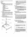
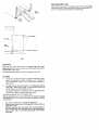
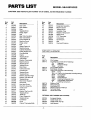
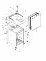
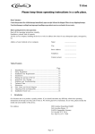
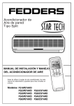
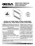
' I_ARS
BEER
Kenmore
DISPENSER
OWNER'S INSTRUCTIONS
MODEL 564.8815022
THIS
BOOK:
r_...
t_, _n. how to operate and care for your beer dispenser. It also offers tips on how to get the
best, as well as lowest cost, performance.
......
VVlI_:;':
_^-;'",
....
,J,,,,,,_
._
,,_l=r_.rn_.rlt
-_
oarts use
the part number. Do not use the illustration number.
For parts
your
or service
nearest
Sears
information,
store
Center, give the complete
ber listed above.
call
or Service
model
num-
ice provided below the model number and serial number
nce. They are located on the model number plate on the
W_
FULL ONE-YEAR
ON BEER DISPENSER
For one year from the date of purchase, when this beer dispenser is operated and maintained according to owner's instructions attached to or furnished with the product, Sears will repair this beer dispenser, free of charge, if defective in
material or workmanship.
FULL FIVE-YEAR
WARRANTY
ON SEALED
REFRIGERATION
SYSTEM
For five years from the date of purchase, when this beer dispenser is operated and maintained according to owner's
instructions attached to or furnished with the product, Sears will repair the sealed system (consisting of refrigerant, connecting tubing and compressor motor), free of charge, if defective in material or workmanship.
WARRANTY SERVICE IS AVAILABLE BY CONTACTING THE NEAREST SEARS
STORE OR SERVICE CENTER THROUGHOUT THE UNITED STATES.
This warranty gives you specific legal rights, and you may also have
other rights which vary from state to state.
Sears, Roebuck and Co., Dept. 698/731A, Sears Tower, Chicago, IL 60684
Part No. 302104
SEARS,
ROEBUCK
AND CO., U.S.A.
Read and understand these instructions thoroughly before installing
beer dispenser.
b.
c.
ASSEMBLY
1.
2.
3.
Carton Inventory
Unpack and inspect the parts. Make sure all items are present
and in good condition.
1 Draft arm assembly (Package includes 1 gasket for
draft arm and 1 washer for connection to keg tapper)
1 CO2 regulator
1 CO2 cylinder
1 Keg tapper (Sankey type)
1 Cleaning kit
1 Pressure tube
2 Hose clamps
2 Keg supports (wooden plates)
1 CO2 cylinder retainer (spring)
1 Guard rail
1 Drip tray
4 Wheel casters
4 Hex head screws (5mm dia x 15mm long)
16 Machine screws (5mm dia x 12mm long)
8 Small screws (5mm dia x 10mm long)
Install casters
a.
Empty the cabinet and then lay down the beer dispenser
sideways so that the door hingeside comes to the top. Be
careful not to cause dents or scratches on the cabinet.
Placing outer carton underneath the cabinet is
recommended.
b. Install casters to the four bottom corners of the cabinet
with the four machine screws (5mm dia x 12mm long) for
each caster.
c. Stand the cabinet upright.
4.
Push wingnut and beer tube of draft arm assembly
through hole in top of cabinet until draft arm is resting on
cabinet top.
Align holes in draftarm base with holes in gasket and pilot
holes in cabinet top, then secure draft arm to cabinet top
with four hex head screws (5mm dia x 15mm).
Install Guard Rail (See Fig. 1).
a. Place guard rail on cabinet top and secure guard rail with
eight small screws.
INSTALLATION
"
1.
Install beer dispenser on stronq,,lev_-IftnnLA_ia
light, heatZJb'0_sa_"a_moi-sture. -
2.
Connect to-120Vr,
use extension cord. Use __q,,_X_tb
grounded W'_ff'6"0t1"b
.'t_"_
,
direct sunout_et. Do not
three-prong
..
,.,
WARNING: Unless the _'d_O_"_gr-_nding method'Js'io/lowed,
you are not _rotep_=d_,.agaim_-severe 'or lethal
sh0_k in'_h+_'event
of a short circuitof an electrical
cq.mponer=Lor_widng
of beer dispenser.
TEMPERATURE CONTROL
1.
Controlis located on rear. Firstset the control at NORMAL position. Wait for 24 hours to check the temperature then adjust
temperature control, if needed.
DEFROST
1.
Install Draft Arm Assembly (See Fig. 1).
a.
Slide gasket over wingnut on bottom of draft arm assembly beer tube. Slide gasket up beer tube to draft arm base.
Beer dispenser will not require much defrosting since the
door opening is at a minimum. Defrost when V4inch frost is
built up on the cold plate. The best time to defrost is when
the keg is changed. To defrost, set temperature control at
OFF position and leave door open until ice melts. Defrost
water will accumulate at the bottom of interior cabinet
which can be absorbed with a sponge or towel.Do notus6
heating devices or sharp objects to speed defrosting
as this could damage cabinet liner of cold plate. Reset
temperature control after defrosting is completed.
Draft Arm Assembly
Hex. Head
Screw
INSTALLATION
OF BEER SYSTEM
i
1.
Installing
CO
2
Cylinder
and CO2 Regulator
I
WARNING:
Gasket
CO2 GAS CAN BE DANGEROUS
Read front pages of "Draught Beer Facts" book included in your cleaning kit for safety precautions
before installaing the CO2 cylinder.
Guard Rail .,_ •
//
Small Screw
OPERATING INSTRUCTIONS FOR CO2 CYLINDERS
Do not operate valve control unlesscylinder is completely
installedand connected.
TURN HANDWHEEL
FULLY COUNTERCLOCKWISE
AS FAR AS IT WILL GO-.-
IMPORTANT: If valve is not fullyopened the stem may not
seal properly against the upper packing washer and the
valve may leak. If leak occurswhen fully opened, tighten
down packing nut under handwheel then open and close
valve fully several times. Replacement packing washer
must be ordered directly from valve manufacturer whose
name is stamped on valve.
Fig 1.
-2-
Pressure
Vessel
• Donotremove
valvefromCO2
cylinder.
• CO2cylinder should be handled only by trained, experienced personneland in accordance with the safe handling practices recommended by the current C.G.A. pamphlet P-l*.
• Keep out of reach of children.
• Visually inspect monthly or more frequently. If cylinder
shows evidence of corrosion or mechanical damage, it
should be inspected and tested in accordance with the
current C.G.A. pamphlets C-1" or C-6* or it should be
replaced.
a.
Your CO2 cylinder is shipped empty to avoid any possible
accident during transportation.
When you purchase the
first keg of beer, get CO_ cylinder filled by your beer
distributor.
b.
Follow the procedure on the inside front cover page of
"Draught Beer Facts" book for installation of CO2 regulator
to CO2 cylinder.
NOTE:
c.
CHARGE ONLY WITH DRY CARBON DIOXIDE
• Do not charge with carbon dioxide unless the pressure
rating stamped on CO2 cylinder is 1800 PSI or greater.
• When charged with carbon dioxide do not exceed a fill
density of 68%. (Fill density is a percent ratio of the
weight of gas in the cylinder to the weight of water that
the cylinder will hold at 60°F).
• If cylinder has been exposed to temperatures in excess
of 350°F., it must be destroyed.
Improper use of cylinder couldcause seriousbodily injury
or property damage.
• C.G.A. pamphlets are published by the Compressed
Gas Association, 500 5th Ave., New York, N.Y.
d.
2.
Shutoff valve on CO2 cylinder may be different in
shape. Do not open shutoff valve until pressure
tube, keg tapper and beer keg are connected
to
CO2 regulator.
Connect pressure tube (clear plastic tube) to CO2 regulator at nipple. Secure connection with hose clamp. To do
this, place hose clamp over tube and squeeze both ends
of hose clamp so that locking teeth will mate.
Place CO2 cylinder at right rear corner inside beer dispenser cabinet in upright position. Fasten CO2 cylinder
with CO2 cylinder retainer (spring) provided. Hook both
ends of retainer to holes in cold plate. (See Fig. 2.)
WARNING:
To avoid personal injury and/or property damage, always secure CO2 cylinder with retainer to prevent it from falling. Should CO2
cylinder valve become accidentally damaged
or broken off, CO2 cylinder can become an
unguided missile.
Installing Keg Tapper and Beer Keg.
a.
The Sankey type keg tapper supplied with beer dispenser
is the most widely used in the United States. However,
some other type keg tappers, such as Golden-Gate, European Sankey or Hoff-Stevens are still being used. Before
installing keg tapper, check with your beer distributor to
make sure that the Sankey type keg tapper can be used.
Cold Plate
If you need a keg tapper other than Sankey type, it is recommended
to purchase the tapper you need from your
beer distributor keeping the Sankey type keg tapper for future use because the Sankey system is becoming more
widely used.
If you wish to have the Sankey type keg tapper exchanged
with another type keg tapper, please return collect the
Sankey type keg tapper to the address
the type of keg tapper you need:
below specifying
Sanyo E & E Corp.
2001 Sanyo Avenue
San Diego. California 92173
2nd hole from right.
Hook this end first.
A'r-rN:
b.
1 st hole from front.
Retainer (Spring)
Hookthisendlast.
c.
CO2Cylinder
d.
e.
-3-
Service
Dept.
Make sure the keg is properly tapped, then open shutoff
valve on CO2 regulator. To install beer keg into cabinet follow the steps below (see Fig. 3).
,•
Wet the surface of keg supports (wooden plates)
•
Lean keg supports on the front bottom edge of
cabinet.
•
•
Fig. 2
Customer
Make sure shutoff valve on CO2 regulator is in closed position. Connect pressure tube to nipple of keg tapper (use
hose clamp). Connect beer tube from draft arm to keg tapper (fasten securely with washer and wingnut).
Make sure that beer faucet and keg tapper are in closed
position, then tap a keg. Open keg tapper valve. (For more
detailed procedures for Items B and C, refer to attached
leaflet.)
Place keg on supports supporting keg by hands.
Push the upper part of keg to stand in upright position
then slide keg supports into cabinet.
•
Make sure that keg and beer tube do not touch cold
plate and that keg and keg supports are properly
positioned not to interfere with door dosing.
Release air caught in draft arm assembly by opening beer
faucet until foam appears. Now dispenser is ready to us.
REPLACING
EMPTY KEG
Close shutoff valve on CO2 regulator then remove keg tappel
from empty keg. To tap a new keg, follow the procedures C, D
and E of "Installing Keg Tapper and Beer Keg."
Keg
j.
Support
Cabinet
Bottom
(1) Lift to upright
i
/
/
I
/
(2) Slide into cabinet.
Fig. 3
OPERATION
Place drip tray under beer faucet. To dispense beer, open beer
faucet quickly all the way. If you have any trouble with beer, refer to
"Draught
Beer Facts"
The recommended
book.
pressure
for the CO2 system is 8-10 Ibs.
CLEANING
1.
To maintain
good-tasting
system is required.
your convenience.
cleaning kit.
2.
beer,
Complete
Refer to
periodical
cleaning
of beer
cleaning
kit is provided
the instructions
included
for
in
To clean cabinet inside and outside, mix 2 tablespoons baking
soda with 1 quarter warm water, or use mild soap. Never use
strong cleanser,
scouring
powder
or pads.
Do not put the drip tray in dishwasher, it is not dishwasher
Vacuum the tubing on outside back twice a year.
To provide
protective
Regular applications
rust. Waxing cleans
contaminants.
care of the painted
safe.
finish:
of wax or polish provide vital protection against
the surface and seals out moisture and other
Use a wax or polish that is suitable for appliances.
Apply the wax or polish when the refrigerator is new and then at
least twice a year.
Between waxings, clean the cabinet with the same polish or
with a CLEAN soft cloth dampened with a mild household detergent. Rinse with a CLEAN lightly dampened cloth and DRY
thoroughly.
PARTS LIST
CAUTION:
Illus.
No.
1.
2.
3.
4.
5.
6.
7.
8.
9.
10.
11.
12.
13.
14.
15.
16.
17.
18.
19.
20.
21.
22.
23.
24.
25.
26.
27.
28.
29.
30.
31.
32.
33.
34.
35.
36.
37.
38.
39.
40.
41.
42.
43.
44.
45.
Use Kenmore
part number
MODEL
on all orders,
Part
No.
Description
300746
300747
300748
Door Liner
Door Gasket
Door
300308
300749
300459
Tapping Screw
Hinge, Upper
Bolt
300750
300751
BeerTube Insulation
Beer Tube Sleeve
300752
300140
Evap. Bracket (4)
Machine Screw
300753
300459
Hinge, Lower
Bolt
300754
300755
Wheel Caster (4)
Machine Screw
300756
300757
300758
300759
300308
300760
Cabinet Assembly
Power Supply Cord
Cord Bushing
Clamp
Tapping Screw
Thermostat
300165
300463
Bracket, Thermostat
Machine Screw
300774
300775
300308
300308
300761
300762
300141
Tapping Screw
Tapping Screw
Back Cover
Cold Control Dial
Control Knob
300776
300777
300778
300308
300308
300763
300764
300308
300765
300766
300767
Tapping Screw
Tapping Screw
Bracket, Top Rear Right
Bracket, Top Rear Left
Tapping Screw
Back Cover Support
Guard Rail
Hex Head Screw
300768
300769
Draft Arm Assembly
Small Screw
300770
300771
300308
300772
300103
300308
300096
Drip Tray
Bracket, Top Front (2)
Tapping Screw
Table Top
Plate, Support (4)
Tapping Screw
Condenser
300100
300479
Dryer
Clamp, Thermostat Bulb
564.8815022
not the illustration
number.
Illus.
No.
Part
No.
Description
46.
47.
300773
300480
Evaporator Assembly
Machine Screw
48.
49.
300494
300475
Tapping Screw
Insulation, Tube
50.
51.
52.
301957
301956
300736
Retainer, Relay Cover
Relay Cover
PTC Thermistor
53.
54.
55.
302017
300430
300413
Compressor
Grommet (4)
Bolt
56.
302016
Overload Protector
PARTS NOT ILLUSTRATED
Part
No.
300779
300780
300781
302015
302104
300784
Description
CO2 Cylinder
CO 2 Regular (consists of the following)
740
Regulator
624
Pressure Gauge
1600c
Air Cock
CO 2 Cylinder Retainer
Keg Tapper, Sankey
Cleaning Kit (consists of the following)
584P
Pump
t 841-1A Cap and Jar Assembly (including tubing)
905W
Faucet Brush
904A
Hose Brush
4350
Faucet Wrench
1000-1
Cleaning Compound (1 lb.)
DBF
Draught Beer Facts Book
JK
Cleaning Instructions
Pressure Tube
Hose Clamp (2)
Keg Support (2)
Owner's Instruction Manual
Technical Sheet
Use & Care Label
OPTIONAL KEG TAPPERS (Not Included)
300786
300787
300788
300789
-5-
European Sankey
Golden Gate, Vent
Golden Gate, Key Tap
Hoff-Stevens
34
1
33
2
4
29
26
23
22
18
12
13
14
55
53
56
52
49
48
7
41
i
46
45
"TR" DRAUGHT
ARM PARTS
D-19-60AC
_)
_
4301
--
4302
--
4306
--
4308
_--4311
\
,_
4312
\
--
4313
O I0
(
I
759
D9R
_,_
•
4318
4322
r
,
4324
4328
I
D-8
D7P
D-6
D-5N
D-2
DI2-2P
D12-1
_'_
©
D14-9
i
L
0-15-2P
D 16
DI7-8
_...____jJ
-8-
Part No.
Description
D-19-60AC
759
Beer Tube Assembly
Washer
D-2
D-5N
Coupling Nut
Shank
D-6
Outside Flange
D7P
D-8
Inside Flange
Lock Nut
D9R
Gland
D-10
Inverted Flare Nut
4301
Black Knob
4302
Knob Lever Collar
4306
Knob Lever Bonnet
4308
FrictionWasher
4311
Ball Washer
4312
Brass Lever
4313
Stainless Steel Lever
4316
Body
4318
4322
Coupling Gasket
T-R Shaft
4324
T-R Valve Seat
4326
T-R Shaft Nut
4328
4330
Snap Ring
Sleeve
D12-2P
Cap
D12-1
Cap O-Ring
D-15-2P
Flange Cover
D14-9
D-16
Cylinder
Gasket
D17-8
Cylinder Insulation
8336
4119
51702