1
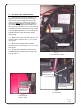
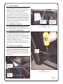
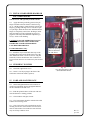
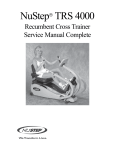
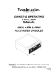
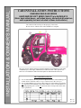
INSTALLATION & OWNER’S MANUAL
CAB INSTALLATION INSTRUCTIONS
KAWASAKI MULE 600 SERIES
HARD AND/OR SOFT SIDED CAB KIT (p/n KAF600-012)
(Note: hard sided doors, soft sided doors, and anti-draft panel are
sold separately but are included in these instructions.)
The contents of this envelope are the property of the owner.
Be sure to leave with the owner when installation is complete.
This cab is shown with the following optional equipment: hard sided doors, work lights,
windshield wiper, strobe light, and antenna for overhead console. Other options not
shown are: soft sided doors and an anti-draft panel for underneath the bench seat.
RECOMMENDATIONS:
1) It is recommended that the tire pressure be adjusted as follows when installing a cab
on this vehicle: front tires to have 11.5 p.s.i. and rear tires to have 18.0 p.s.i.
2) It is recommended that two (2) heavy-duty springs (p/n 92145-0400) be used in the
rear suspension when installing a cab on this vehicle. It is also recommended to set
the spring adjusting sleeve of the rear shock unit at the circled position in the chart
below (position 4).
Rev. G
p. 1 of 9
DESIGN CONCEPT
Curtis cabs feature an assembly of parts designed for your vehicle which require
adjustment and alignment of components to accommodate vehicle variations and
provide proper weather protection. For accurate installation, proper operation, and
years of satisfaction, please read and understand the installation instructions.
From all of us at Curtis, we thank you for choosing our product.
ADDED
WEIGHT
Curtis Cabs, blades and general accessories
add additional weight to the base vehicle. All
Curtis accessory weights are listed in product
brochures. Deduct the accessory's total weight
from the vehicle's rated capacity and never
exceed the vehicle's rated capacity including
driver and passenger.
CAB INSTALLATION
BEFORE YOU START
HELPFUL REMINDERS:
A. Refer to parts diagram toward the back of this manual to help identify
parts during the assembly process.
B. To assist with the cab installation, leave all bolts
loose for later adjustment unless otherwise specified.
C. Read and understand all instructions before beginning.
D. Plastic washers have been supplied to provide a weather seal around all
exterior fasteners. The plastic washer should be installed under each
bolt head directly against the outside cab surface. Care should be taken
not to over tighten the fasteners and damage the plastic washer. Also
use metal washers as required.
E. Apply a clear silicone sealant to seal any minor gaps that may occur due
to vehicle variations.
TOOLS REQUIRED:
Set of standard and metric sockets and open end wrenches
One 3/8” Drive Ratchet
One 3/16” Allen Wrench
One Phillips Head Screwdriver
Grease
Drill
11/32” Drill Bit
Scissors
Rev. G
p. 2 of 9
1. INSTALL ANTI-DRAFT PANEL
Note: this item is sold separately from the cab kit
and the door kits.
1.1 If a hard rear window will be installed, make sure
the sheetmetal filler underneath the expanded metal
screen is reversed so the small bent lip faces forward as
shown in Fig. 1.1 (this acts as a shelf for the hard rear
window to rest on). Remove and re-install three (3)
bolts holding this filler in place. Note: this filler can
also be reversed even for a soft rear curtain installation
(in case down the road a hard rear window is desired).
1.2 Remove the seat back and install the anti-draft
panel onto the back side of the seat back making sure
that the clear plastic window in the anti-draft panel is
oriented over the fuel gauge which is towards the lower
passenger’s side of the vehicle. Note: one edge of the
panel is notched to fit around the seat hinges. Re-install
the seat back through the original mounting holes and
secure with the original nuts.
1.3 Raise the lower seat 90 degrees as shown in Figure 1.3. Spread out the anti-draft panel as would appear
to be appropriate. Panel may pass under seat and velcro
to front of tube beneath front edge of seat. Pull back
one area or section at a time in order to assess where to
apply the hook (rough) velcro on the vehicle. Per Fig.
1.1, install four (4) pieces of hook (rough) velcro as
high up as possible underneath the forward facing
sheetmetal lip to the left and right sides of the bolt
heads. NOTE: adhesive backed velcro should be applied to a clean, dry surface at room temperature.
1.4 Install the anti-draft panel to the newly applied
hook velcro on the vehicle. Lower seat back down.
bent sheetmetal lip
to be facing forward
towards the seat
velcro to be placed snuggly up
under the lip and facing the seat
ref.: hard rear
window shown
Fig. 1.1 (view from front of passenger’s side of vehicle)
lower seat rotated up 90 degrees
ref.: driver’s side
hip restraint
apply hook (rough) velcro here, etc.
Fig. 1.3 (view from side of driver’s side)
2. INSTALL FRONT MOUNTS
2.1 Loosen the front cab bar bolts and slide the front
mount in place between the cab bar and the plastic
hood as shown in Fig. 2.1. Repeat for passenger’s side.
Leave the bolts loose so that the front mounts can be
adjusted when the side frames are installed in step 5.
front mount
front cab bar bolts
Fig. 2.1 (view from front of driver’s side)
Rev. G
p. 3 of 9
3.
INSTALL HARD REAR WINDOW
OR SOFT REAR CURTAIN
Note: these items are sold separately from the cab
kit. Hard rear windows come with the purchase of
hard sided doors. Soft rear curtains come with the
purchase of soft sided doors.
For Hard Rear Window:
3.1 CRITICAL: Make sure the sheetmetal filler
underneath the expanded metal screen has the
small bent lip pointing forward as shown in Fig. 1.1
on the previous page (this acts as a shelf for the
hard rear window to rest on).
3.2 Remove the protective film from the rear window
and install it up against the inside surface of the expanded metal screen as shown in Fig. 3.2. NOTE: the
bulb rubber on the perimeter of the rear window should
be facing toward the front of the vehicle.
rear roof mount
shown in place
remove this protective
film before installation
Fig. 3.2
(view from front of vehicle)
3.3 Proceed to step 4 to install the rear roof mount.
For Soft Rear Curtain:
3.4 Install the six (6) supplied stud snaps to the rear
roof mount. Orient so that the locknuts are on the outside of the cab and the snaps are on the inside of the
cab.
locknuts to be installed
against this flange surface
3.5 Install the supplied adhesive-backed hook (rough)
velcro to the inside surface of each rear leg. Note: adhesive-backed velcro should be applied to a clean, dry
surface at room temperature.
3.6 Install the rear curtain to the newly installed stud
snaps and hook velcro. Note: the bottom of the rear
curtain velcros to the top inside edge of the anti-draft
panel which has factory installed mating loop (soft)
velcro. If an anti-draft panel is not being used, then
install the supplied loop (soft) velcro as high up as possible underneath the forward facing sheetmetal lip
shown in Fig. 1.1 on the previous page. Cut the velcro
into four pieces to go on the left and right sides of the
bolt heads.
4.
90 degree mounting flange
on rear roof mount
INSTALL REAR ROOF MOUNT
Vehicle prep.: remove the upper rear cab bar bolts,
washers, and nuts so the rear roof mounts can be installed.
4.1 Install the rear roof mount as shown in Figures 3.2 and 4.1. Re-install the upper rear cab bar hardware that was removed above in step 4 (vehicle prep.).
Orient the bolts so that the heads are towards the inside
of the vehicle and the locknuts are towards the outside
of the vehicle.
Fig. 4.1
(view from front driver’s side of vehicle)
Rev. G
p. 4 of 9
5. INSTALL LEFT SIDE FRAME
5.1 Position the left side frame as shown in Fig. 5.1.
Important: place the front of the side frame over the
front of the cab bar system and pivot the rear of the
side frame into place so that the rear leg of the side
frame installs behind the rear roof mount which was
just installed in step 4. If installing a hard sided cab,
the rear leg of the side frame is to be in front of the rear
window. NOTE: make sure the ball stud mount, which
is for the windshield gas shock, is over the cab bar tube
before pivoting into place. Ref.: handle with care so the
Expand-a-foam does not get distorted or damaged
while pivoting.
ref.: ball stud mount
is inside the side
frame in this vicinity
5.2 Bolt the rear leg of the side frame to the rear roof
mount two places as shown in Fig. 5.2. Use 3/4” long
carriage bolts.
5.3 Bolt the front of the side frame to the front
mounts two places as shown in Fig. 5.3. Use 3/4” long
carriage bolts.
5.4 The right side frame will be installed after the
windshield support is installed in the next step on the
next page (step 6.1).
Expand-a-foam strip
Fig. 5.1
(view from driver’s side)
locknuts to be on
inside surface of cab
NOTICE: rear leg of side
frame must be behind the
rear roof mount
bolt heads on this
outside surface
Fig. 5.3
(view from front
of driver’s side)
Fig. 5.2
(view from front
of driver’s side)
Rev. G
p. 5 of 9
6. INSTALL WINDSHIELD SUPPORT
6.1 Position the windshield support underneath the
left side frame as shown in Fig. 6.1. Install one (1) bolt
through hole and into weldnut. Use a 3/4” long button
head bolt. The five (5) rear holes will receive hardware
once the roof is installed in step 9 on the next page.
side
frame
windshield support
to be underneath
side frame
6.2. With assistance, install the right side frame so
that the windshield support is inside (underneath) the
side frame similar to Fig. 6.1. Important: place the
front of the side frame over the front of the cab bar
system and pivot the rear of the side frame into place
so that the rear leg of the side frame installs behind the
rear roof mount which was installed in step 4. If installing a hard sided cab, the rear leg of the side frame is to
be in front of the rear window. NOTE: make sure the
ball stud mount, which is for the windshield gas shock,
is over the cab bar tube before pivoting into place.
Ref.: handle with care so the Expand-a-foam does not
get distorted or damaged while pivoting. Install one
bolt through hole and into weldnut. Use a 3/4” long
button head.
install one (1) bolt here with the bolt
head on the outside of the vehicle
Fig. 6.1
(view from driver’s side)
7. INSTALL WINDSHIELD
7.1 Have the following items ready to use: two plastic spacer blocks, four flat head screws (1 3/4” long),
four flat steel washers, and four 5/16-18 locknuts. With
assistance, place the windshield in place on the windshield support with the 3/4” thick plastic spacer blocks
underneath the plastic hinges for mounting up against
the outer surface of the windshield support per Fig. 7.1.
Adjust windshield alignment with latches engaged and
tighten. Note: hinges are plastic components. Do not
overtighten. Torque to 7 ft. lbs. max..
plastic hinge with spacer block
8. INSTALL RUBBER FILLER
8.1 Install the small piece of 3” flat bulb rubber on
the sheet metal edge of the flat part of the opening in
the rear roof mount as shown in Fig. 8.1. NOTE: the
loose end of the bulb rubber should rest against the
inside surface of the bent tab as shown in Fig. 8.1.
(This serves to close the air gap above the cab bar.)
ref.: bent
tab is on
this side
side
frame
gas shocks to be
installed in step 12
press on
the 3” flat
bulb
rubber
here
Fig. 7.1
(view from passenger’s side)
Fig. 8.1 (inside view of upper
rear cab bar tube on driver’s side)
Rev. G
p. 6 of 9
9. INSTALL ROOF
Note: Use a Phillips head screw driver to punch a hole
through the headliner at eight (8) bolt hole locations.
Punch holes from the inside out to avoid having the
headliner pull away from its glued surface.
9.1 Position the roof so that the row of five holes
lines up with the row of five holes in the windshield
support per Fig. 9.1. Install 3/4” long carriage bolts in
all roof holes except the two front corners. The left and
right front corner holes will require 1” long carriage
bolts. Locknuts to be on the inside of the cab. Plastic
washers to be under the bolt heads which are to be on
the exterior surface of the roof.
ref.: holes for
optional work
lights
ref.: shown with
optional windshield wiper
10. TIGHTEN ALL BOLTS
10.1 Push bottom portion of side frames tight against
the vehicle and tighten all bolts (including the four
large cab bar bolts that were loosened in step 2.1.
Fig. 9.1
(view from passenger’s side)
11. SECURE FLOORBOARDS
11.1 Before drilling, make sure the bottom portion of
the side frames are tight against the vehicle.
11.2 Drill an 11/32” diameter hole through the vehicle
floorboards using the square holes in the side frame
floorboard as guides per Fig. 11.2. A total of four holes
will need to be drilled (two per side).
11.3 Install 3/4” long carriage bolts in these newly
drilled out holes. Locknuts to be underneath the vehicle.
12. INSTALL GAS SHOCKS
12.1 With all bolts tight and floorboards drilled and
secured, open the windshield and attach the two gas
shocks as shown in Fig. 12.1. The rod end of the gas
shock must be installed down as shown. Press the button on the compression fastener to lock the gas shock
to the ball stud.
11/32”
diameter
drill bit
large canister
end of gas
shock
Fig. 11.2
(view from driver’s side)
small piston
end of gas
shock
Fig. 12.1 (view from passenger’s side)
Rev. G
p. 7 of 9
13. INSTALL HARD SIDED DOORS OR
SOFT SIDED DOORS
Note: doors are sold separately from the cab kit.
13.1 Apply lubricant (preferably grease) to the pin
hinges mounted on the side frames as shown in Figure 13.1. With assistance, install the doors onto the pin
hinges by guiding both hinge sleeves onto their respective pin hinges. Work the doors back and forth until the
hinges are completely seated. Note: the hinges, inside
latch, and striker pin can be adjusted for proper engagement. The rotary latch should be adjusted to get
two (2) “clicks” when latching.
CAUTION: FOR SAFE OPERATION, DO NOT
DRIVE WITH DOORS OPEN. MAKE SURE
DOORS ARE CLOSED AND PROPERLY
LATCHED WHEN DRIVING.
For Hard Sided Doors only:
13.2 Install the vinyl coated cable door stops to the
mounting tabs located on the inside upper area of the
door and the side frame. Use the 5/16 x 3/4” long hex
head bolts, washers and locknuts. Note: locknuts can
be left one turn loose for free rotation of eyelets around
bolts.
grease the pin hinges
that are fastened to
the side frames
14. FINISHING TOUCHES
14.1 Install the supplied nut covers.
14.2 Install 1 1/8” Heyco plugs in the front of the
side frames at the front mounts (4 places).
Fig. 13.1
(view from passenger’s side)
(hard sided door shown)
15. CARE AND MAINTENANCE
15.1 Check and tighten hardware after 40 hours of
operations. Periodically inspect and tighten hardware
for the remainder of the unit’s life.
15.2 Wash the painted surfaces of the unit with commercial automotive cleaning products.
15.3 Clean windows with glass cleaner.
15.4 Vinyl components should be washed with a mild
solution of warm soapy water.
15.5 Clear vinyl can be easily scratched. Be careful
cleaning frost or snow from windows. Do not roll curtains in cold weather. The windows become stiff and
may crack. Keep windows clean.
Rev. G
p. 8 of 9
Kawasaki Motors Corp., U.S.A.
Irvine, California 92718-2016
KAWASAKI MULE 600 CAB PARTS LIST p/n KAF600-012
ROOF
QTY.
WINDSHIELD
P/N
1
QTY.
KA600-01
1
*REFLECTORS
*HEADLINER
* (2) HEYCO PLUGS
SEAM BULB
* RELEASE
LATCHES
(UPSIDE
DOWN)
*HINGES
* GAS SHOCK
MOUNTS
*TRIM-LOK (4 SIDES)
WINDSHIELD SUPPORT
QTY.
* 3/4" OFFSET SIDE
BULB W/ 1/4" GRIP
P/N
1
* WELDNUTS
(ONE PER
SIDE)
P/N
KA600-02
KA600-03
REAR ROOF MOUNT
QTY.
P/N
1
KA600-04
1
1
KA600-05L
KA600-05R
* HEYCO PLUGS
* SERIAL # DECAL
& W/S WARNING
DECAL (INSIDE)
* 1/2" WEATHERSEAL
(INSIDE) (TYP.)
FRONT MOUNTS
LEFT
RIGHT
UNITIZED SIDE
FRAMES
QTY.
LEFT
RIGHT
1
1
P/N
KA600-09L
KA600-09R
* STRIKER
* 3/4" SIDE
BULB WITH
1/4" GRIP
AND ONE
WINDOW
CLIP
RIGHT
* 1/4" x 3/4" EXPAND-A-FOAM (INSIDE, NOT UNDERNEATH) (14" LONG STARTING AT FLOORBOARD)
(TOWARDS INSIDE RADIUS BEND IS BEST)
* GAS SHOCK MOUNTS
* HINGE PINS
LH & RH
RIGHT
LEFT
9PR02
* 5/8" REGULAR
BULB
* 1/4" x 3/4"
EXPAND-A-FOAM
(BETWEEN
HEYCO HOLES)
9PR20
* 1/4" x 3/4" EXPAND-A-FOAM
ADDITIONAL SERVICE PARTS
QTY/UNIT
* IN-HOUSE
APPLICATIONS
* 5/8" REGULAR
BULB (LEFT
FRAME ONLY)
(ONE LONG
PC. IS OKAY)
* 5/8" REGULAR
BULB (RIGHT
SIDE FRAME ONLY)
(4 1/2" LONG)
* 5/8" REG. BULB
(2 1/2" LONG) (FROM
TUBE) (L & R SIDE
FRAMES)
* GRIT PAPER
LEFT
1
1
1
1
1
1
1
1
1
1
1
p/n
DESCRIPTION
9GL-36x49
9PH007 & 9BLK01
9WL02L
9WL02R
9PH006
9PH005
MOLDED WINDSHIELD ASSEMBLY
POP OUT WINDSHIELD HINGE KIT-SINGLE
POP OUT WINDSHIELD RELEASE LATCH KIT-LH
POP OUT WINDSHIELD RELEASE LATCH KIT-RH
UNITIZED FRAME HINGE KIT-LH
UNITIZED FRAME HINGE KIT-RH
HARDWARE FASTENER KIT
WINDSHIELD GAS SHOCK
LEFT FRONT SIDE WINDOW W/ RUBBER
RIGHT FRONT SIDE WINDOW W/ RUBBER
WINDOW MOUNTING CLIP
KA600HWK-01
9GS03
9GL-M6L
9GL-M6R
9WC01
ACCESSORIES
9PRO1
W/ 1/4" GRIP
9PR26
Rev. G
p. 9 of 9