1
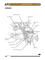
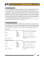
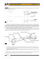
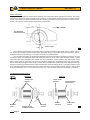
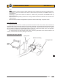
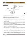
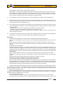
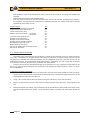
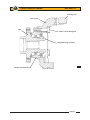
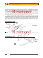
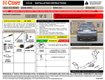
Lotus Service Notes
Section CI
FRONT SUSPENSION
SECTION CI
Sub-Section
Page
General Description
CI.1
3
Geometry & Adjustments
CI.2
3
Anti-Roll Bar
CI.3
7
Suspension Disassembly/Assembly
CI.4
8
Front Wheel Bearings
CI.5
10
Page 1
Lotus Service Notes
Section CI
GENERAL LAYOUT
Spring/damper unit
Top wishbone
Steering tie rod
Upper swivel
joint
Track rod
end
Steering
arm
Anti-roll bar
mounting
Anti-roll bar
Bottom wishbone
Hub carrier
Wheel hub
Lower steering swivel joint
c34b
Page 2
Lotus Service Notes
Section CI
CI.1 - GENERAL DESCRIPTION
The fully independent front suspension comprises, on each side of the car, upper and lower wishbones, a
concentric coil spring/telescopic damper unit, and a tubular anti-roll bar. A forged steel hub carrier, provides a
mounting for a the hub bearing unit to which the road wheel is attached via four spline socket bolts.
The upper and lower 'A' frame wishbones are fabricated from steel tube, the upper wishone braced by
sheet steel gussets at its apex, and the lower wishbone braced by a tubular strut at its base. The inboard ends
of both wishbones use replaceable bonded rubber pivot bushes to provide maintenance free articulation, with
a specification providing accurate and responsive dynamic characteristics. The outer ends of both wishbones
incorporate housings into which the upper and lower steering swivel ball joints are pressed. The upper ball
pin is secured to the forged steel, rearward facing steering arm, itself fixed to the hub carrier by two M10 bolts.
The ball pin of the lower swivel joint is secured directly into a tapered hole in the bottom of the forged steel hub
carrier. The Bilstein spring/damper unit acts between the outer end of the lower wishbone and the chassis,
and is fitted with the damper rod lowermost in order to minimise unsprung weight.
A forward mounted tubular steel anti-roll bar, is supported in chassis mounted rubber pivot bushes and is
operated via short ball jointed drop links from the lower wishbones.
CI.2 - GEOMETRY & ADJUSTMENTS
Provision is made for the adjustment of wheel alignment, camber and castor. Under normal service conditions, no periodic scheduled check of the geometry is necessary, although a front wheel alignment check is
recommended when the front tyres are replaced. A full geometry check is required only after front suspension
repair, or if excessive tyre wear is evident, or if steering difficulties are encountered. Before any measurements
or adjustments are made it is essential first to set the vehicle to its ‘mid-laden’ ride height, approximating to
driver and passenger and a half tank of fuel. This will require the vehicle to be ballasted, or tied down:
Standard Elise
Mid-laden ride height (reference height for geometry check);
- front
130 mm below front end of chassis siderail
- rear
130 mm below rear end of chassis siderail
Camber
- optimum
- 0.1°
- tolerance
+ 0.1° to - 0.3°; Max side/side 0.2°
Castor
- optimum
+ 3.8°
- tolerance
+ 3.5° to + 4.1°; max. side/side: 0.35°
Alignment
- optimum
Zero
- tolerance
0.5 mm toe-out to 0.7 mm toe-in overall
(0.07° toe-out to 0.10° toe-in overall)
Steering axis inclination
12° nominal
Roadsport Elise, Exige
Mid-laden ride height (reference height for geometry check);
- front
130mm below front end of chassis siderail
- rear
130mm below rear end of chassis siderail
Camber
- optimum
- 0.3°
- tolerance
- 0.1° to - 0.5°; max. side/side: 0.2°
Castor
- optimum
+ 3.8°
- tolerance
+ 3.5° to + 4.1°; max. side/side: 0.35°
Alignment
- optimum
Zero
- tolerance
0.5 mm toe-out to 0.5 mm toe-in overall
(0.07° toe-out to 0.07° toe-in overall)
Steering axis inclination
12° nominal
Page 3
Lotus Service Notes
Section CI
Alignment
Wheel alignment refers to the parallelism of the wheels when viewed from above and is crucial to vehicle
stability, handling and tyre wear.
Difference between
rim measurements
= overall toe out
FRONT
Individual
toe out
angle
c26
Alignment is measured either by the angle a wheel makes with the vehicle centre line, or the difference in
dimension between the wheel rim to wheel rim measurement at the front and rear of the wheel at hub centre
height. The wheels are said to 'toe-in' when the wheel paths converge ahead of the vehicle, and 'toe-out' when
they diverge. Wheel alignment is designed to vary with both steering angle (Ackerman) and suspension travel
(bump steer) and should be measured only 'straight ahead' at the specified ride height.
Front wheel alignment is adjusted be screwing the track rods into or out of the track rod outer end ball
joints. In order to preserve the required bump steer characteristic and steering symmetry, the effective length
of each track rod must remain equal - adjust each track rod by a similar amount.
Track rod end flats
Steering rack gaiter
Track rod end
Steering arm
Steering track rod flats
Track rod end locknut
c28a
-
Hold the track rod end using the flats provided, and slacken the locknut. Repeat for the opposite side.
Turn each track rod a similar amount. As a guide, turning both track rods by one quarter of a turn will alter
overall toe-out by approx. 2.0 mm.
When adjustment is correct, hold each track rod end and tighten the locknuts to 80 - 82 Nm (58 - 60 lbf.
ft).
When slackening or tightening the track rod end locknuts, it is important that the torque reaction is resisted
using the track rod end flats, and that the ball joint itself is not allowed to be stressed.
Page 4
Lotus Service Notes
Section CI
Camber Adjustment
Camber is the angle from vertical of the wheel when viewed from the front, and is said to be negative when
the wheel leans inwards at the top (positive when leaning outwards). The primary purpose of camber is to
achieve the maximum efficiency of the tyre under cornering loads and body roll, with the specification closely
allied to a particular wheel/tyre combination. The camber angle changes with suspension travel, becoming
more negative on bump, and should be measured only at the specified ride height. Incorrect camber can result
in handling deficiencies and excessive tyre wear.
Camber angle
Vertical
c29
Wheel centreline
Camber adjustment is effected by adding or deleting shim plates between the steering arm (to which the
upper steering swivel joint is fixed) and the hub carrier.
Camber adjustment
shimplate
Steering arm
Hub carrier
-
c30a
Shimplates are available in 1mm and 3mm thicknesses.
Reducing the shim pack thickness will increase negative camber. Adding shims will reduce negative
camber.
A 1mm shim plate will alter camber by approximately 0.25°.
Apply Permabond A130 (A912E7033) to the two steering arm fixing bolts, and tighten to 45 Nm
Page 5
Lotus Service Notes
Section CI
Castor Adjustment
Castor is the angle from vertical of the steering axis of the wheel when viewed from the side. Its primary
purpose is to provide a natural straight running tendency of the steered wheels with forward vehicle motion.
Castor angles have a complex interaction with other steering geometries and if unbalanced or outside of specification, can result in various stability and handling deficiencies.
FRONT
Top & bottom
steering swivels
Castor angle
c27
The wishbone pivot bushes are bonded rubber type with a plastic flanged outer sleeve, a plain steel inner sleeve, and a plastic interleaf sleeve within the rubber bush to control the flexing characteristic. The top
wishbone rear bush, identified by a blue paint mark, has no interleaf sleeve.
The top wishbone pivots are sandwiched between the walls of transverse chassis box sections, the pick
up points in which are reinforced either with machined inserts, or in the case of the foremost position, a thick
alloy plate, each being bonded to the chassis with epoxy adhesive. Spacer washers are fitted ahead of and
behind each of the top wishbone pivot bushes to allow the wishbone to be displaced forwards or backwards,
with an associated change of castor angle. A rubber faced snubber washer fitted against the rear face of the top
wishbone front bush prevents metal to metal contact under extreme braking forces. The spacer washers may
be re-distributed between the front and rear of each pivot bush but the snubber washer position, and the total
shim pack thickness of 4 x 1.5mm at each pivot (inc. the 1.5mm snubber washer) must remain unchanged.
Top Wishbone Inboard Fixing
FRONT
Front leg
Rear leg
1.5mm shim
washers
Bonded
plate
Page 6
Rubber faced
snubber washer
1.5mm shim
washers
Bonded
inserts
Plastic
interleaf
Flanged plastic
outer sleeve
Inner steel
sleeve
c32
Lotus Service Notes
-
Section CI
Notes
Shim distribution at the front bush of either wishbone must be copied at the rear bush of that wishbone.
Transferring a 1.5mm shim washer from ahead of, to behind the pivot bushes, will reduce castor by approximately 0.4°.
Transferring a 1.5mm shim washer from behind, to ahead of the pivot bushes, will increase castor by
approximately 0.4°.
Ensure that the load spreading washers are correctly located beneath the bolt heads and nuts as shown
in the drawings.
Ensure that the pivot bolts are tightened only with the vehicle at ride height. Torque to 45 Nm.
CI.3 - ANTI-ROLL BAR
A tubular steel anti-roll bar is mounted in pivot bushes onto the front face of the chassis, and is linked to the
outboard ends of each lower front wishbone via short ball jointed links. The chassis mounted pivots use rubber
bushes for noise isolation, and are retained by alloy clamp brackets. Washers welded to the bar bear against
the inner sides of the bushes to provide lateral location of the bar. Castrol LMX rubber grease, or equivalent,
should be used when fitting the rubber bushes onto the anti-roll bar.
To remove the bar, the alloy bracket at each side, connecting the bottom of the crash structure to the
chassis, must be first be removed by drilling out the rivets.
Anti-Roll Bar Mounting - Rubber
Spacer plate
Rubber mounting
Clamp bracket
Fixing
bolts
c40
Page 7
Lotus Service Notes
Section CI
Anti-Roll Bar Drop Link
Lower wishbone
Anti-roll bar
drop link
Anti-roll bar
c31
CI.4 - SUSPENSION DISASSEMBLY/ASSEMBLY
The suspension may be disassembled without the use of any special tools other than a 'Torx' socket for
the hub bearing carrier bolts, and a spring compressor, required only if the spring is to be removed from the
damper unit. With the car on a wheel free lift and with the front wheels removed:
1. Remove the wheelarch liner(s) as appropriate.
2.
Remove the two bolts securing the brake caliper to the hub carrier, release the flexible hose from the top
wishbone, and support the caliper aside without straining the brake hose. Release the single countersunk
screw, and remove the brake disc.
3.
Remove the nut securing the track rod end into the steering arm, and use a ball joint splitter to separate
the rod end from the arm.
4.
Remove the nut securing the top swivel joint to the steering arm, and use a ball joint splitter to separate
the joint from the arm. Remove the two M10 fixing bolts and remove the steering arm from the hub carrier,
taking care not to misplace the camber adjustment shim plates.
5.
Remove the nut securing the lower swivel joint to the hub carrier, and use a ball joint splitter to separate
the ball pin from the carrier.
6.
Remove the bolts securing the spring/damper unit to the lower wishbone and chassis anchor bracket, and
withdraw the unit, noting the spacer washers fitted at the top end.
7.
Disconnect the anti-roll bar drop link from the lower wishbone, and remove the lower wishbone front pivot
bolt.
8.
Remove the lower wishbone rear pivot bolt from within the cabin footwell, and withdraw the wishbone.
9.
Before removing the two pivot bolts for the top wishbone, take careful note of the distribution of castor
adjustment washers. Move the steering rack to full lock to provide clearance for the withdrawal of the
wishbone rear pivot bolt. Withdraw the wishbone.
10. The wishbone pivot bushes comprise a rubber bush bonded to a steel inner sleeve and a flanged plastic
outer sleeve. The bushes may be pressed out of the wishbone eyes, and new bushes fitted using suitable press tool dollies. Smear the outer surface of the new bush with IPC 'P-80' rubber lubricant emulsion
Page 8
Lotus Service Notes
Section CI
(A082C6042V) to ease fitment, and assemble as follows:
Top wishbone - insert from the outside of both pivot eyes (from front of front eye, and rear of rear eye).
Lower wishbone - insert from the inside of both pivot eyes (from rear of front eye, and front of rear eye).
Note that all top wishbone pivot bushes are common with the exception of the top wishbone rear pivot,
which contains no interleaf sleeve and is identified by a blue paint mark.
11.
Top and bottom swivel joints are identical, and may be replaced if necessary using a suitable press.
12.
If the anti-roll bar is to be removed; remove the front alloy undertray, and, by drilling out the rivets, the
small alloy closing panel at each side of the crash structure below the anti-roll bar. Release the a.r. bar
clamps and drop links, and withdraw the bar.
13.
The road spring may be removed from the damper using a suitable spring compressor to allow the spring
lower slotted seat to be withdrawn. Note that spring upper seat is located by a square section circlip on
the damper body:
- Standard Elise: Use centre of 3 grooves for mid-laden ride height of 130mm.
- USA Elise: Use lower of 3 grooves for mid-laden ride height of 135mm.
- Elise with Roadsports suspension package and non-USA Exige: Use the upper of 2 grooves for midladen ride height of 130mm.
14.
To remove the hub bearing unit from the hub carrier, release the three Torx head bolts and withdraw the
complete unit. The hub unit is not serviceable, and is replaced complete if faulty.
Reassembly
Re-assemble the suspension in reverse order to disassembly with the following notes:
Take care to assemble each pivot bolt with the correct washers/snubbers/spacers as shown in the diagrams.
Smear the shank of each pivot bolt with PBC grease, but do not allow contamination of the threads.
Take care to refit the original camber adjustment shimpack, and distribute the castor shims as noted on
removal.
Top ball joint plinth fixing bolts:
The bolts securing the steering arm/top ball joint plinth to the hub carrier were upgraded in March '04 at
VIN serial number 1537 (approx.) in order to commonise with motorsport applications. Earlier type 8.8
grade bolts should be tightened to 45 Nm; Later 10.9 grade bolts to 68 Nm. The bolt grade is stamped
around the head of the bolt. The thread of both bolt types should first be treated with Permabond A130
(A912E7033V).
After re-fitting a standard anti-roll bar, ensure that the crash structure closing panels are re-rivetted.
Lubricate the rubber type anti-roll bar mountings with rubber grease and the Nylon type with MoS2
grease.
Apply Permabond A130 (A912E7033V) to the threads of the steering arm bolts.
Lubricate the ends of the damper top eye bush with rubber grease.
Press the brake pedal to reposition the pads before driving the car.
If the car suffers a suspension impact sufficient to damage a wheel rim, careful attention should be paid to
all related suspension components. Such forces can cause stretching of the lower ball pin and consequent
fixing nut torque loss. As a safety precaution, it is recommended that in all such cases, the lower ball joint
and the two bolts securing the upper ball joint plinth to the hub carrier are renewed.
The Service Schedule specifies that the security of the front and rear suspension is checked at each service.
For cars used on race tracks, or in similar conditions, suspension components and torque checks should be
carried out between sessions. This operation requires that all the principal suspension pivot bolts are torque
checked, noting the following points:
Where a bolt is tapped into a housing or weldnut, and relies on a thread locking compound for security, it
is important to appreciate that if the bolt is disturbed, the locking compound must be re-applied. The following
procedure should be adopted for all such fixings:
Check the torque of the fixing.
If the specified torque is attained without the fixing being disturbed (moving), take no further action.
If the bolt moves, the locking action of the thread adhesive will have been compromised. Remove the
Page 9
Lotus Service Notes
-
Section CI
bolt completely, clean off all old adhesive using a wire brush and acetone, and apply new adhesive as
specified.
Refit the bolt and tighten to the specified torque.
If for any reason a bolt is found to have become loose, and the car has been operated for any period in
this condition, the bolt should be renewed as a standard precaution and related components carefully
inspected for hole ovality or wear.
Torque Settings:
Upper and lower wishbone pivot bolts
Upper swivel joint to steering arm
Lower swivel joint to plinth
Steering arm to hub carrier - 8.8 grade
- 10.9 grade
Track rod end to steering arm
Damper to lower wishbone
Damper to top anchor bracket
Damper anchor bracket to chassis
Hub bearing unit to hub carrier
Brake caliper to hub carrier
Anti-roll bar rubber bush mounting clamps
Anti-roll bar drop links
Nm
45
55
55
45
68
30
45
45
25
90
45
25
45
CI.5 - FRONT WHEEL BEARINGS
The sealed front wheel bearings are contained in a steel housing secured to the hub carrier with three
'Torx' bolts. The double row, angular contact, ball bearing is retained in the outer housing and also onto the
hub spigot by a shoulder and a peening operation, and is inseparable for service. Note that all four hub assemblies are common, and incorporate a wheel speed sensor in the bearing unit, with a flying lead terminating
in an electrical connector plug secured by a camber shim plate bracket.
If there is found to be any discernible free play in the hub bearing, or any roughness or tight spots can be
felt, or any signs of lubricant expulsion are evident, the hub assembly should be replaced - there is no provision for adjustment.
To Replace Hub Bearing Assembly
1. With the wheel removed, release the two fixing bolts, and remove the brake caliper from the hub carrier.
Support clear of the brake disc without straining the flexible hose. Release the single countersunk screw
and withdraw the brake disc from the hub.
2.
Using a Torx socket, release the three bolts securing the hub bearing unit to the hub carrier.
3.
Fit the new hub bearing unit to the hub carrier and retain with the three Torx bolts. Torque tighten to 90
Nm.
4.
Refit the brake disc and caliper, using Permabond A130 (A912E7033) to the threads of the caliper fixing
bolts and torque tightening to 45 Nm. Pump the brake pedal to reposition the pads before driving the
car.
Page 10
Lotus Service Notes
Section CI
Steering arm
Hub carrier
Hub
Hub to carrier fixing bolt
Swaged bearing retention
c41a
Double row ball bearing
Page 11
Lotus Service Notes
Section CI
CI.3 - ANTI-ROLL BAR
Reserved
A tubular steel anti-roll bar is mounted in pivot bushes onto the front face of the chassis, and is linked to
the outboard ends of each lower front wishbone via short ball jointed links. On cars fitted with the motorsport
anti-roll bar, the ends of the uprated bar are equipped with 5 holes to allow some adjustment of roll stiffness to
be made. Standard setting is centre hole. Using a more forward hole increases stiffness.
Two types of mounting are used to secure the anti-roll bar to the front face of the chassis. Standard
Elise models use rubber pivot bushes for noise isolation, retained by alloy clamp brackets. Washers welded
to the bar bear against the inner sides of the bushes to provide lateral location of the bar. Castrol LMX rubber
grease, or equivalent, should be used when fitting the rubber bushes onto the anti-roll bar.
For the anti-roll bars used with roadsport suspension and on Exige, the bar is secured by two Nylon
clamps, fixed to the chassis via the front lower wishone inboard front pivot bolt, with a 'top hat' section steel
spacer preventing the clamp from being crushed. These hard type mountings provide optimum steering response but will transmit more noise and require periodic lubrication with MoS2 grease at 3,000 mile (5,000 km)
intervals. Note that the two types of mounting require differently shaped bars, with that for the rubber mounts
being positioned higher on the chassis than the hard mount version.
Anti-Roll Bar Mounting - Rubber
Spacer plate
Rubber mounting
Clamp bracket
c40
bolt
tube
Reserved
Anti-Roll Bar Mounting - Nylon
Page 12
Wishbone pivot
Spacer