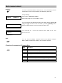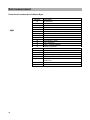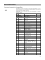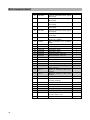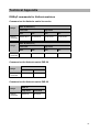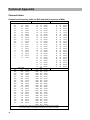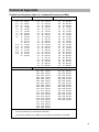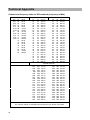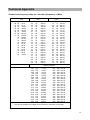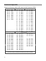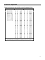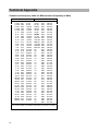
1
Operating Manual
Satellite / TV / Radio
Test Receiver
MSK 24
Order No. 208 323
2
Preface
Preface
Dear Customer,
Kathrein-Werke KG has made every effort to ensure that this manual is
correct and complete. No liability can be assumed for any mistakes that
may still be contained in the manual or for any damage resulting from
such mistakes.
This manual may not be copied in full or in part nor reproduced nor
distributed in any other form without written permission from Kathrein KG.
We reserve the right to make alterations to this manual without prior
notice. This applies in particular to alterations required for technical
improvement.
All product names and trademarks used in this manual are the property of
the relevant companies.
All rights reserved.
Validity of this manual
This manual is valid for MSK 24, order no. 208 323
As of August 2000
3
Contents
Contents
Preface ................................................................................................................................................. 3
Validity of this manual....................................................................................................................... 3
Contents................................................................................................................................................ 4
General Notes....................................................................................................................................... 6
Explanation of symbols ........................................................................................................................ 6
Safety instructions ............................................................................................................................... 6
How it operates..................................................................................................................................... 7
Overview of functions........................................................................................................................... 8
Block diagram of MSK 24...................................................................................................................... 9
Technical Data .....................................................................................................................................10
Operating and display elements ..........................................................................................................12
Display elements ................................................................................................................................12
LC display ......................................................................................................................................12
TFT colour screen ...........................................................................................................................12
Connections (right side) ......................................................................................................................12
Overview of the keyboard commands..................................................................................................13
Connections.........................................................................................................................................14
RF input socket ..................................................................................................................................14
External DC voltage supply .................................................................................................................14
Scart output........................................................................................................................................14
Starting up ...........................................................................................................................................15
Switching on the receiver ....................................................................................................................15
Switching off the receiver ....................................................................................................................15
Setup menu........................................................................................................................................16
Factory settings ..............................................................................................................................16
Settings in the setup menu...............................................................................................................16
Calling up the setup menu ............................................................................................................16
Mains and battery operation ................................................................................................................17
Mains operation ..............................................................................................................................17
Battery operation.............................................................................................................................17
Sat measurement.................................................................................................................................18
Standard Switch-Over .........................................................................................................................18
Frequency Display and Entering Frequency .........................................................................................19
Overview of commands in Entering Frequency (SAT) ........................................................................19
Level Measurement ............................................................................................................................20
Level Overflow and Underflow..........................................................................................................20
Tracking Satellites ..............................................................................................................................21
Tracking for Single Frequencies ..........................................................................................................22
Audio Carrier Frequency .....................................................................................................................23
LNB Voltage and 22 kHz / 60 Hz Switch-Over.......................................................................................24
DiSEqC (Digital Satellite Equipment Control) ........................................................................................26
Overview of commands in Framing Byte...........................................................................................27
Overview of commands in Address Byte...........................................................................................28
Overview of commands in Command Byte........................................................................................29
Overview of commands in Data Byte................................................................................................31
Simple Tone Burst DiSEqC .................................................................................................................31
V-SEC (Vario-Satellite Equipment Control)...........................................................................................33
TV measurement..................................................................................................................................34
Standard Switch-Over .........................................................................................................................34
Channel Display and Entering Channel ................................................................................................35
Frequency Display and Entering Frequency .........................................................................................36
Level Measurement (TV).....................................................................................................................37
Level Overflow and Underflow..........................................................................................................37
Tracking for Single Frequencies ..........................................................................................................38
Audio Carrier Distance and Level.........................................................................................................39
Measuring the Audio Carrier Distance and Level of Nicam Audio Carriers:..........................................40
NICAM – Measuring Audio Bit Error Rates ........................................................................................40
Calling up Measuring Audio Bit Error Rates: .....................................................................................40
4
Contents
FM measurement .................................................................................................................................41
Frequency Display and Entering Frequency .........................................................................................41
Level Measurement ............................................................................................................................41
Level Overflow and Underflow..........................................................................................................41
Tracking for Single Frequencies ..........................................................................................................42
Spectrum measurement.......................................................................................................................43
Sat Spectrum .....................................................................................................................................43
TV Spectrum ......................................................................................................................................43
FM Spectrum......................................................................................................................................44
Maintenance ........................................................................................................................................45
Changing the battery...........................................................................................................................45
Customer service............................................................................................................................45
Technical Appendix.............................................................................................................................46
Signal-to-noise distance......................................................................................................................46
DiSEqC commands for Kathrein matrices .............................................................................................47
Command set for Kathrein matrix 9xx-series .....................................................................................47
Command set for Kathrein matrix EXR 20.........................................................................................47
Command set for Kathrein matrix EXR 22.........................................................................................47
Channel tables ...................................................................................................................................48
Channel and frequency table for B/G standard (frequency in MHz).....................................................48
Channel and frequency table for L standard (frequency in MHz).........................................................49
Channel and frequency table for D/K standard (frequency in MHz).....................................................50
Channel and frequency table for I standard (frequency in MHz)..........................................................51
Channel and frequency table for M1 Japan standard (frequency in MHz)............................................52
Channel and frequency table for M/N standard (frequency in MHz).....................................................53
Channel and frequency table for M/N standard (frequency in MHz).....................................................54
Notes....................................................................................................................................................55
5
General Notes
General Notes
This manual has been written for persons with a basic knowledge of
electrical engineering. At every step users who have already worked with
measuring instruments can find the necessary commands in an overview.
In addition, the following examples help to explain the operating steps.
Explanation of symbols
Instructions shown with the warning symbol must be observed as
otherwise the MSK 24 may be damaged or destroyed.
+
0
This symbol provides information on measuring functions and refers you
to chapters containing further information on a subject.
This symbol is followed by an example of the measuring function just
explained.
ë
Here you will find an overview of the commands for the button
combinations for the relevant measuring function.
[Button]
The button to be pressed on the receiver.
Safety instructions
Always observe VDE safety regulations!
Use only fuses that have the same cutout characteristics.
Observe the following upper limits when supplying signals:
• HF input: max. 120 dBìV (60dBmV)
• Do not apply a DC voltage >22 V to the HF socket
• Do not apply a low-frequency AC voltage to the HF socket
The receiver is also live when disconnected.
Use only the power supply unit supplied to power the MSK 24.
A voltage of between 10 V and 20 V is available at the RF input socket
depending on the programming. The source can supply up to 500 mA.
Parts supplied
1 plug-in power supply unit
1 BNC measuring cable
1 adapter for BNC socket to F socket
1 adapter for BNC socket to F plug
1 adapter for BNC socket to IEC socket
1 adapter for BNC socket to IEC plug
6
How it operates
How it operates
The MSK 24 is designed as a universal portable test receiver for TV, SAT
and FM radio for both battery and mains operation. A built-in lead battery
with 2.8 Ah and a plug-in power unit for 230 V AC are included with the
receiver.
A microcontroller is responsible for controlling the unit, scanning the
keyboard and displaying frequency and level on the LC display.
Receiving frequencies are indicated in MHz. Levels are measured with a
peak or average value detector and indicated digitally in dBìV or dBmV.
Correction values are determined when levels are calibrated for the
MSK 24. They are stored in an EEPROM. Precise level measurements
can thus be made.
There is a bar display on the front display to help find transmitters. In
addition, there is an audio tracking signal to facilitate aligning of the
antenna as the display does not have to be observed.
The audio section with its built-in loudspeaker is capable of processing
and reproducing various audio frequency satellite signals, audio
frequency TV signals complying with the B/G, D/K, I, M1 (Japan) and M/N
standards, as well as FM audio. NICAM and AM audio reproduction
(L standard) is also possible.
All currently known requirements are covered thanks to an LNB supply
voltage of 10-20 V / max. 500 mA with steps of 0.1 V, the superimposition
of 22 kHz / 60Hz and the facility of sending DiSEqC or V-SEC
commands.
The built-in TFT colour screen allows pictures to be assessed locally.
7
Overview of functions
Overview of functions
Function
SAT mode
TV mode
FM mode
Mains and battery operation
*
*
*
Level measurement by entering frequency
*
*
*
Level measurement by entering channel
*
Level-dependent acoustic signal
*
*
*
Loudspeaker for acoustic check
*
*
*
Reception of multiple standards (B/G, D/K, I, L,
Nicam, M/N, M1)
Nicam audio reception and L standard
*
*
*
Audio carrier setting
*
*
Audio carrier measurement
*
Adjustable LNB voltage supply
LNB current measurement
*
22 kHz / 60 Hz switch-over
*
DiSEqC, V-SEC
*
DVB measurement (QPSK, QAM)
*
*
Scart output (video and audio)
*
*
Nicam audio,
measurement
8
reception
and
bit
error
rate
*
* (audio
only )
Block diagram of MSK 24
Block diagram of MSK 24
9
Technical Data
Technical Data
Power supply
Mains operation
Battery operation
Capacity
230 VAC 50/60 Hz
12 V / 2.8 Ah lead battery
Dimensions
width 260 mm, height 90 (120) mm, depth 165 mm
incl. accessories (plus bag)
Weight
4 kg (incl. bag)
Safety standards
CE label
Protection class II
VDE EN61010
Display
TFT screen, alphanumerical LCD with 2 x 16 characters,
bar display, background illumination
Temperature range
+5 °C to +45 °C
Frequency range
SAT
TV
FM
920 MHz...2150 MHz
45 MHz...867 MHz
88 MHz...108 MHz (45 MHz...867 MHz)
Channel allocation
TV
B standard
D/G/I/K standard
M/N/M1 standard
Frequency tuning
SAT
TV
FM
in 0.125 MHz steps
in 50 kHz steps
in 50 kHz steps
Measuring errors
SAT
TV/FM
max. ±2 dB
max. ±2 dB
7 MHz
8 MHz
6 MHz
RF input
coaxial socket, BNC, 75Ù
RF input separator
0 – 60 dB in 4 dB steps
Level measurement range
30 dBìV – 120 dBìV
Measuring bandwidth
SAT
TV
FM
Measuring detector
SAT
TV
FM
Return loss
6 MHz
250 kHz
250 kHz
average value display
peak value display
average value display
>6 dB
FM threshold
SAT
<9 dB
Audio IF bandwidth
SAT
TV
FM
230 kHz / 150 kHz
230 kHz
230 kHz
Audio deemphasis
SAT
TV/FM
50 ìs
50 ìs
10
SAT DVB
TV DVB
6 MHz
6 MHz
Technical Data
Audio processing SAT FM audio processing
5.0 MHz…8.99 MHz in steps of 10 kHz
TV FM + Nicam in quasi parallel audio mode
AM in parallel mode (only L standard)
TV
B/G standard
Audio carrier 1 = 5.5 MHz, Audio carrier 2 = 5.74 MHz
D/K standard
Audio carrier 1 = 6.5 MHz, Audio carrier 2 = 6.26 MHz
I standard
Audio carrier 1 = 6.0 MHz
M/N standard
Audio carrier 1 = 4.5 MHz, Audio carrier 2 = 4.72 MHz
M1 standard
Audio carrier 1 = 4.5 MHz
L standard
AM 6.5 MHz. Nicam = 5.85 MHz
B/G standard
Nicam = 5.85 MHz
I standard
Nicam = 6.552 MHz
FM
FM audio processing
45 MHz...867 MHz
Audio carrier measurement
TV
B/G standard
D/K standard
I standard
L standard
M/N standard
M1 standard
Nicam decoder
Audio carrier distance
TV
5.58 MHz with B/G, D/K, and L standards
6.552 MHz with I standard
Nicam bit error rate
TV
0 - 4 x 10
LNB voltage supply
SAT
0, 10 V...20 V, max. 500 mA
LNB control
SAT
22 kHz, 60 Hz, DISEqC, Simple DiSEqC, V-SEC
Scart output
5.5 MHz, 5.74 MHz, 5.85 MHz
6.5 MHz, 6.26 MHz
6.0 MHz, 6.552 MHz
6.5 MHz, 5.85 MHz
4.5 MHz, 4.72 MHz
4.5 MHz
-2
1 Vss / 75 Ohm
11
Operating and display elements
Operating and display elements
SAT . TV . FM
MSK 24
TEST - RECEIVER
7
8
9
Sat-Ctrl
LNB
4
5
6
Level
Ch-Frq
RF
Sat/TV
LNB
+
SC
1
4
1
2
5
2
0
./S
3
6
3
MHz
!
75
Off
FM
TFT colour screen
LC display
Scan
RF input socket
LED
2ndF
Volume control
Spect
Setup
Std
Keyboard
Display elements
LC display
Depending on the mode the following information is shown in the LC
display:
FR: 954.0 MHz
LEV: 40.0 dBuV
SAT
•
the set channel,
•
the set frequency,
•
the function called up,
•
the mode,
•
the level measured and
•
the measured values.
TFT colour screen
The colour screen has a diagonal of 4“ and a resolution of 238 x 480
pixels. The light intensity is 250 cd/m².
Connections (right side)
Scart connector without inputs
DC voltage supply – for supplied
power supply unit only
12
Overview of the keyboard commands
Overview of the keyboard commands
Button
Brief description of the function for
SAT/TV
SAT
TV
FM
Switch-over to TV reception
Switch-over to SAT reception
Switch-over to SAT reception
-
Decrease current values
+
Increase current values
0...9
Enter numbers
•
Decimal point for
./S
Decimal point for
numerical entries
numerical entries
•
Decimal point for
numerical entries
Call up special channel
ENTER
Confirm numerical entries
2ndF +
Call up second command level
button
FM
Switch-over to FM
Call up the DISEqC/
Sat-Ctrl
V-SEC menu / LNB
No function
LNB voltage menu and
LNB
current measurement
Ch-Freq
No function
•
Call up the frequency menu
•
Switch-over from channel to
No function
frequency display and vice versa.
Std
DVB/analogue switch-over
•
DVB/analogue switch-over
•
Standard switch-over
SC
(Subcarrier) Audio carrier menu
Scan
Search for a satellite irrelevant of frequency
Level
Switch on level-dependent acoustic signal with bar display
Spect
Spectrum analysis
Setup
Define receiver settings
Keyboard of MSK 24:
7
8
9
Sat-Ctrl
LNB
See above for details
4
5
6
Level
Ch-Frq
Sat/TV
+
SC
1
4
1
2
5
2
0
./S
3
6
3
Scan
MHz
FM
2ndF
Spect
Setup
Std
13
Connections
Connections
RF input socket
The signal received from the antenna system or the cable network is fed
in here (BNC coaxial socket).
The remote powering voltage (for LNB) can be adjusted from 10 to
20 VDC and can be switched off. When the LNB voltage is switched on,
the LED next to the RF input socket lights up.
Make sure that there is
•
no voltage level over 120 dBìV,
•
no positive DC voltage over 22 VDC,
•
no negative DC voltage and
•
no AC voltage.
on the RF input socket.
The input circuit can be seriously damaged if this warning is not heeded.
External DC voltage supply
The MSK 24 can be powered from the mains or its built-in battery.
Voltage is supplied externally from the supplied power supply and
recharging unit through the DC socket on the right side of the housing of
the MSK 24.
Make sure that
•
only the supplied power supply unit is used,
•
the power supply unit is only connected to the receiver when it is to
be used to supply power. Otherwise the battery of the MSK 24 will be
discharged!
Scart output
The visual and audio signals are available at the Scart socket on the right
side of the MSK 24 for assessment on an external monitor.
No outputs are available!
Wrongly wired connectors may damage or destroy the receiver.
14
Starting up
Starting up
Switching on the receiver
Software V1.0
SN: 000222
ACCU
•
Connect the receiver with the battery charger/power supply unit to the
mains supply.
•
Turn the on/off switch towards the right.
•
Set the desired volume.
The LC display shows the software version and serial number of the
MSK 24 for approx. 1 second.
[
]
Then the LC display indicates the capacity of the battery for approx.
3 seconds.
One segment is equivalent to approx. 20% of the total capacity (2.8 Ah).
Now apply the receiving signal from the receiver system into the RF input
socket.
LC display:
CH: .02.
LEV: 48.5dBuV
TV
•
channel
•
mode
•
level.
Use the [TV/SAT] button to select the required mode.
Switching off the receiver
Turn the on/off switch towards the left.
15
Starting up
Setup menu
The default setting (status of the MSK 24 when it is switched on) can be
set in the setup menu.
Factory settings
Parameter
POWER ON
Setting
TV
LNB DC
OFF
LEVEL
dBìV
Low Level Mute
ON
Settings in the setup menu
Calling up the setup menu
Press the [2ndF] and [SETUP] buttons.
Press button [1], [2] or [3] to select the appropriate TV, SAT or FM mode.
Press [ENTER] to retain the current setting.
POWER ON
TV=1 SAT=2 FM=3
1. Setup menu
The following request appears:
LNB DC
OFF=1
ON=2
Press button [1] or [2] to switch the LNB voltage supply on or off. Press
[ENTER] to retain the current setting.
2. Setup menu
Level
dBµV=1
dBmV=2
In the next menu press button [1] or [2] to set the measuring unit in which
the level should be displayed. Press [ENTER] to retain the current
setting.
3. Setup menu
CH: .07.
LEV:____.__dBµV
TV
In the next menu you are requested to set the mute function by pressing
button [1] or [2]. Select "ON" to mute the MSK 24 as long as the input
signal on the RF input is below 30 dBìV.
4. Setup menu
Press [ENTER] to retain the current setting.
LOW LEVEL MUTE
OFF=1
ON=2
If you have not altered the factory default setting, the information shown
on the left is displayed.
Default setting
As soon as you have set the low level mute, setup menu 4 is exited
automatically and the default setting displayed.
16
Starting up
Mains and battery operation
The MSK 24 can be powered from the mains or the built-in battery.
Mains operation
Use only the batttery charger/power supply unit supplied for mains
operation. Connect the power supply unit to the voltage supply socket on
the right side of the receiver.
If the receiver is not used for long periods, connect the receiver to the
mains supply now and then (maintenance charging).
Make sure that the power supply unit is not connected to the receiver if it
is not to be used to supply voltage as otherwise the battery will be
discharged.
Battery operation
Battery operation is only possible if the battery is sufficiently charged.
Otherwise the MSK 24 cannot be switched on.
If the battery has been fully discharged, recharge it immediately as
otherwise it may be damaged or destroyed.
Charging begins automatically as soon as the receiver has been
connected to the mains supply. A protective circuit prevents the battery
from being overcharged.
The capacity of the battery is displayed for approx. 3 seconds after the
receiver has been switched on.
With a charged battery the maximum period of operation is approx.
2.5 hours for an LNB supply current of 150 mA.
17
Sat measurement
Sat measurement
Standard Switch-Over
In the SAT mode the MSK 24 can be set to receive the following types of
signal:
•
analogue and
•
digital (DVB).
Overview of commands in Standard Switch-Over in SAT
[2ndF] [STD] Call up standard switch-over menu:
ë
[1]...[2]
Select the standard
1 = analogue
2 = digital (DVB)
Example
Call up digital (DVB) standard:
0
Press [2ndF] [STD]
LC display:
1=ANALOG
2=DIGITAL(DVB)
•
1 = analogue standard
•
2 = digital (DVB) standard
Standard menu
FR:1288.0MHz
LEV: 66.5dBuV
SAT
D
Display for DVB measurement
18
If you press button [2], you will leave the standard menu and the receiver
will be set to DVB measurement.
A "D" appears in the display.
Sat measurement
Frequency Display and Entering Frequency
To measure the level of a received signal, you must first enter the desired
frequency. The LC display shows the frequency and the measured level.
You can enter frequency values from 920 MHz to 2150 MHz in steps of
100 kHz.
Overview of commands in Entering Frequency (SAT)
[SAT/TV] Switch over to SAT reception
ë
[0]...[9]
Enter frequency
[+] [-]
You can alter frequency in steps of 100 kHz
[ENTER] Confirm entry
FR:1288.0MHz
LEV: 66.5dBuV
SAT
LC display:
•
Frequency: 1288 MHz
•
Mode: SAT
•
Level: 66.5 dBìV
Example
Enter frequency 1508 MHz
Press [1] [5] [0] [8] [E NTER]
LC display:
FR:1508.0MHz
LEV: 86.5dBuV
SAT
•
Frequency: 1508 MHz
•
Mode: SAT
•
Level: 86.5 dBìV
A + or – in the display means that MSK 24 has not been tuned in exactly
to the desired carrier. Use the [+] and [-] buttons to adjust the frequency
for the best possible reception. When a vertical line appears in the
display, the frequency has the best possible setting.
Note
+
Press [ENTER] to complete the frequency entry.
The last frequency setting is retained even when the MSK 24 is switched
off provided it was made using "numerical entries" and concluded with
"MHz".
19
Sat measurement
Level Measurement
Once you have set a frequency, the level is measured automatically and
displayed in dBìV or dBmV (depending on the basic configuration) on the
LC display. The input level can be measured in the range of 30 dBìV to
120 dBìV (-30 dBmV to 60dBmV).
LC display:
FR:1508.0MHz
LEV: 86.5dBuV
SAT
•
Frequency: 1508MHz
•
Mode: SAT
•
Measured level: 86.5dBìV
Level Overflow and Underflow
FR:1508.0MHz
LEV: __._dBuV
FR:1508.0MHz
LEV:
dBuV
SAT
SAT
The LC display indicates unterflow at a level <30 dBìV, e.g.
•
Frequency: 1508 MHz
•
Mode: SAT
•
Level: underflow
The LC display indicates overflow at a level >120 dBìV.
The following information appears in the display:
•
Frequency: 1508 MHz
•
Mode: SAT
•
Level: overflow
Note
+
only
20
Levels of DVB-S signals can be measured in the digital reception setting
only.
Sat measurement
Tracking Satellites
The "SCAN" function can search for satellites whose exact transponder
frequencies are unknown. The frequency range from 1000 to 2100 MHz
is scanned continuously to detect signals. If signals are received, the
reception level is indicated in a bar display. The measuring range can be
set to three different sensitivity levels.
The level can be monitored with an audio tracking signal, the volume
being proportional to the level of the signal received. The volume of the
audio tracking signal can be set with the volume control.
Overview of commands in SCAN
[2ndF] [SCAN] Switch over to SCAN operation.
ë
[-] [+]
Change the measuring range of the bar display.
Level range 1: high input level
Level range 2: medium input level
Level range 3: low input level
Exit SCAN by pressing [2ndF] twice.
LC display:
LEV-Range:2
>
SAT
•
Level range 2: medium input level
•
SAT mode
•
Bar display
Example
Calling up the SCAN function
0
• Press the [2ndF] and [SCAN] buttons.
• Rotate the antenna until a level tendency is visible on the bar display.
• Rotate the antenna until the bar display has reached its maximum.
• If necessary, decrease or increase the sensitivity with the [-] and [+]
buttons.
Exit SCAN by pressing [2ndF] twice.
21
Sat measurement
Tracking for Single Frequencies
In the "LEVEL " function you can align an antenna by tracking to receive
the maximum signal. The level tendency can be indicated in the bar
display. The measuring range can be set to three different sensitivity
levels.
The level can be monitored with an audio tracking signal, the volume
being proportional to the level of the signal received. The volume of the
audio tracking signal can be set with the volume control.
Overview of commands in Tracking
[2ndF] [LEVEL
ë
[-] [+]
] Switch over to the tracking mode
Change the measuring range of the bar display.
The measuring range is preselected automatically.
Level range 1: high input level
Level range 2: medium input level
Level range 3: low input level
Exit the LEVEL mode by pressing [2ndF] twice.
LC display:
LEV-Range:2
>
SAT
•
Level range 2: medium input level
•
SAT mode
•
Bar display
Example
Call up the "LEVEL
0
" function.
Press the [2ndF] and [LEVEL
] buttons.
Rotate the antenna until the maximum bar display is reached.
If necessary, decrease or increase the sensitivity with the [-] and [+]
buttons.
Repeat this procedure until you have reached the maximum level.
Exit the LEVEL menu by pressing [2ndF] twice.
22
Sat measurement
Audio Carrier Frequency
A video signal has several audio carrier frequencies assigned to it. With
the MSK 24 you can select the main carrier and subcarrier frequencies to
hear them separately. The audio carrier frequency can be set in steps of
10 kHz from 5.0 MHz to 8.99 MHz. The audio carrier bandwidth is
automatically switched over from "wide" (280 kHz) to "narrow" (150 kHz)
at 7.00 MHz
The following factory settings for the audio carrier frequencies are stored
in the receiver when it leaves the factory:
Button
Frequency in MHz
Bandwidth in kHz
[1]
[2]
5.80
6.50
280
280
[3]
[4]
[5]
6.65
7.02
7.20
280
150
150
[6]
[7]
7.38
7.56
150
150
[8]
[9]
7.74
7.92
150
150
Overview of commands in Audio Carrier Frequencies (SAT)
ë
[2ndF] [SC]
Call up audio carrier menu
[1]...[9]
Select audio subcarrier
[-] or [+]
Change audio carrier frequency in 10 kHz steps
[ENTER]
Manually switch audio carrier bandwidth
wide = 280 kHz, narrow = 150 kHz
Exit audio carrier menu by pressing [2ndF] twice.
Example
Call up audio carrier with 7.38 MHz
0
Press [2ndF] [SC] [6]
LC display:
SC: 7.38MHz
BW:NARROW
SAT
•
Audio subcarrier: 7.38 MHz
•
Audio carrier bandwidth: narrow = 150 kHz
•
Mode: SAT
Note
+
After the SAT mode has been called up, the MSK 24 is always set to the
audio carrier 7.02 MHz. Changes made to the frequency of the audio
carrier are only retained until you exit the SAT mode.
23
Sat measurement
LNB Voltage and 22 kHz / 60 Hz Switch-Over
The LNB supply voltage is available at the RF socket. This is confirmed
by the LED next to the RF socket which lights up when the voltage supply
is switched on. The current consumed by the connected LNB is indicated
in the LC display.
The 22 kHz or 60 Hz square wave signal that can be added is
superimposed on the LNB voltage. It is needed to switch multifeed
systems or high/lowband LNBs.
The LNB voltage can be
•
switched off = 0V
•
set from 10 V to 20 V in steps of 0.1 V
•
short-circuit protected (max. current 500 mA)
The following voltages can be called up by pressing the relevant button:
LNB voltage
Button
0V
12V
[0]
[1]
14V
18V
[2]
[3]
Overview of commands in LNB Voltage
ë
[2ndF] [LNB]
Call up the LNB menu
[0]...[3]
Select the LNB voltage
[-] or [+]
Change the LNB voltage in 0.1 V steps
[7]
60 Hz signal on/off
[8]
22 kHz signal on/off
Exit the LNB menu by pressing [2ndF] twice.
Example
0
Call up the LNB voltage 14 V:
Press buttons [2ndF] [LNB] [2]
LC display:
LNB:14,0V
150mA
•
LNB voltage: 14 V
•
Current consumption: 150 mA
Note
+
24
By pressing the [+] or [-] buttons you can change the LNB voltage in
steps of 0.1 V.
By calling up another function, e.g. [2ndF] [CH-FRQ], you can exit the
LNB menu automatically.
Sat measurement
Example
0
Switch on the 22 kHz signal.
Press button [8].
LC display:
LNB:14,0V
150mA
22kHz
•
LNB voltage 14 V
•
Current consumption 150 mA
•
The 22 kHz signal is switched on.
Note
By pressing button [8], you can switch off the 22 kHz signal.
+
By calling up another function, e.g. [2ndF] [CH-FRQ], you can exit the
LNB menu automatically.
25
Sat measurement
DiSEqC (Digital Satellite Equipment Control)
The DiSEqC system is used to control systems with extended control
facilities. DiSEqC uses serial, bidirectional transmission with one master
and one or more slaves. The data bits are formed by modulation of the
pulse width of the available 22 kHz carrier and are superimposed with
600 mVss of the LNB remote voltage. The digital code words are made up
of 8 data bits and one additional parity bit to detect transmission errors.
Several code words form a DiSEqC command. Input of the code words is
in hexidecimal code.
code words
Framing
P
Address
P
Command P
Data
P
parity bit
The MSK 24 can also transmit signals to DiSEqC 1.0 but it cannot
receive them.
Overview of commands in DiSEqC
ë
[2ndF] [SAT-CTRL]
Call up the DiSEqC menu
[0]...[9]
Enter the code words in hexadecimal code 0...9
[.] [0]...[5]
Enter the code words in hexadecimal code A...F
Button
Hex Code
[.] [0]
[.] [1]
A
B
[.] [2]
[.] [3]
[.] [4]
C
D
E
[.] [5]
F
[-] or [+]
Move the cursor among the various code words:
Framing, Address, Command and Data
[.] [6]
Delete the entire command string up to the cursor
position
[ENTER]
Send the command string
Exit the DiSEqC menu by pressing [2ndF] twice.
26
Sat measurement
Example
You want to test the Kathrein matrix EXR 22. The command set for the
matrix EXR 22 is E0 00 24 (LNB High) and E0 00 20 (LNB Low).
0
Call up DiSEqC:
SAT-CTRL
V-SEC=2
LNB=1
DiSEqC=3
Press buttons [2ndF] [SAT-CTRL]
Press button [3] to call up the DiSEqC control.
SAT-CTRL menu
DiSEqC-Framing
You can now enter the data bits for each code word using the buttons [0]
to [9] and [./S]. Send the control command by pressing [ENTER]. The >
symbol indicates that the control command has been sent.
DiSEqC menu
DiSEqC-COMMAND
E0 00 24 >
The command set to control the Kathrein matrix EXR 22 has been
entered and sent.
DiSEqC menu
Note
+
You can find the DiSEqC command sets for the Kathrein matrices
EXR 20, EXR 22 and the 9xx series in the Technical Appendix.
Overview of commands in Framing Byte
ë
HEX
Byte
Description
E0
E1
E2
Command from master, single transmission
Command from master, repetitive transmission
Command from master, answer expected, first transmission
E3
Command from master, answer expected, repeated
transmission
E4
E5
E6
Answer from slave, "OK", no error detected
Answer from slave, command not supported by slave
Answer from slave, parity error detected
E7
Answer from slave, command not detected
27
Sat measurement
Overview of commands in Address Byte
Hex byte
00
ë
28
Description
All equipment
10
11
Every LNB, matrix or SMATV
LNB
12
14
15
LNB with loop-through
Matrix (switcher)
Matrix (switcher) with loop-through
18
20
SMATV
Every polarizer
21
22
30
Maximum rotation (full skew) with lineal polarization
Set polarizer in steps
Every positioner
31
32
Polar / Azimuth positioner
Elevation positioner
33
34
40
Combined positioner
LNB positioner
Installation help
41
60
Help to set signal strength
Reserved for allocated addresses
70
71
"Intelligent slave interface" for "Proprietary multimaster bus"
Interface for users and checked head stations
Fx
OEM expansion
Sat measurement
Overview of commands in Command Byte
ë
The MSK 24 can send commands in accordance with DiSEqC 1.0 but it
cannot receive them. All commands that require DiSEqC 2.0 (to send and
receive) are shown in grey in the table.
Commands shown in bold type are used preferentially for Kathrein
switching matrices.
Hex
byte
00
01
Command
Description
Reset
Clr Reset
Reset DiSEqC microcontroller
Clear reset flag
02
Standby
Switch off the peripheral power
supply unit
-
03
Power on
-
04
Set Content
Switch on the peripheral power
supply unit
Set the contention flag
05
Contend
-
06
Clr Content
Feedback only if the contention
flag has been set
Clear contention flag
07
Address
Feedback only if the contention
flag has not been set
-
08
Move C
1
09
Move
10
11
Status
Config
Change address if contention
flag has been set
Change address if contention
flag has not been set
Read status register flags
Read configuration flags
14
Switch 0
Read switching status flags
(Committed Port)
-
15
Switch 1
-
16
Switch 2
Read switching state
(uncommitted port)
Expansion option
17
20
Switch 3
Set LO
Expansion option
Call up the low local oscillator
frequency
-
21
Set VR
Call up vertical polarization or
circular polarization with right
rotation
-
22
23
Set Pos A
Set S0A
Select satellite position A
Select switch option A
-
24
Set Hi
-
25
Set HL
26
Set Pos B
Call up the high local
oscillator frequency
Call up vertical polarization or
circular polarization with left
rotation
Select satellite position B
27
28
Set S0B
Set S1A
-
29
Set S2A
Select switch option B
Call up matrix S1 input A (input
B inactive)
Call up matrix S2 input A (input
flags
Number of
data bytes
-
-
-
1
-
-
-
-
29
Sat measurement
30
2A
Set S3A
2B
Set S4A
2C
Set S1B
2D
Set S2B
2E
B inactive)
Call up matrix S3 input A (input
B inactive)
-
Call up matrix S4 input A (input
B inactive)
Call up matrix S1 input B (input
A inactive)
Call up matrix S2 input B (input
A inactive)
-
Set S3B
Call up matrix S3 input B (input
A inactive)
-
2F
Set S4B
-
30
Sleep
31
Awake
Call up matrix S4 input B (input
A inactive)
All bus commands are ignored
except for "Awake".
Bus commands are accepted
again.
38
39
Write N0
Write N1
Set port group 0
Set port group 1
1
1
3A
3B
40
Write N2
Write N3
Read A0
Expansion option
Expansion option
Read analogue value A0
1
1
-
41
48
Read A1
Write A0
Read analogue value A1
Set analogue value A0
1
49
4F
50
Write A1
Write A7
LO string
Set analogue value A1
Set analogue value A7
Read current frequency
1
1
-
51
LO now
-
52
LO Lo
53
LO Hi
58
59
Write Freq
Ch.No.
60
61
Halt
Go E
Read current frequency (table
entry number)
Read Lo frequency table entry
number
Read Hi frequency table entry
number
Write channel frequency
Set
the
selected
channel
number (receiver)
Stop positioner
Move positioner towards east
62
64
Go W
P Status
Move positioner towards west
Read positioner status register
65
6C
Read Pos
Goto
Read positioner counter
Move positioner motor
counter value, Hi, Lo
6D
Write Pos
Set positioner counter, Hi, Lo
-
-
2 or 3
2
-
to
2
2
Sat measurement
Overview of commands in Data Byte
ë
An appropriate data byte only needs to be sent when the command byte
requires data byte(s). You can see this in the above command byte table.
You can find out which data byte has to be sent to which command byte
in the data sheets for the relevant receiver.
Orbit
position
Switch position
H/V
Switch position
LNB
Data
byte
1
V
V
Lo
Hi
F0
F1
H
H
Lo
Hi
F2
F3
V
V
Lo
Hi
F4
F5
H
H
Lo
Hi
F6
F7
V
V
Lo
Hi
F8
F9
H
Lo
FA
H
V
Hi
Lo
FB
FC
V
H
Hi
Lo
FD
FE
H
Hi
FF
2
3
4
Simple Tone Burst DiSEqC
A simplified form of DiSEqC control is the Simple Tone Burst DiSEqC
procedure. In this Simple DiSEqC two switching states are possible: tone
burst and data burst.
Overview of commands in Simple DiSEqC
[2ndF] [SAT-CTRL]
ë
Call up the SAT–CTRL menu
[3]
Call up the DiSEqC menu
[0]
Enter tone burst
[1]
Enter data burst
[ENTER]
Send the command string
Exit the DiSEqC menu by pressing [2ndF] twice.
31
Sat measurement
Example
0
SAT-CTRL
V-SEC=2
Call up Simple DiSEqC:
LNB=1
DiSEqC=3
Press buttons [2ndF] [SAT-CTRL]
Press button [3] to call up DiSEqC control.
SAT-CTRL menu
DiSEqC-Framing
The cursor must be positioned on the left with the [-] button. Press button
[0] or [1] to call up the Simple DiSEqC menu.
DiSEqC menu
DiSEqC-SIMPLE
0 Tone BURST
Simple DiSEqC menu
32
>
Press [ENTER] to send the control command. The > symbol indicates
that the control command has been sent. Press button [1] to switch to
data burst.
Sat measurement
V-SEC (Vario-Satellite Equipment Control)
V-SEC provides unidirectional communication between satellite receivers
and peripheral components in a satellite receiving system and serves to
control intelligent multiswitches with several inputs, coaxial relays or
rotation systems.
V-SEC uses 8-bit data transfer by pulse width modulation of the 22 kHz
carrier frequency. There is 8-bit data transfer from the test receiver to the
peripheral equipment through the existing coaxial cable. The V-SEC
control signals are assigned to the components by destination addresses.
After output of the V-SEC data, standard signals of 14 V/18 V and 0/60
Hz/22 kHz are still available. Input of the code word is in hexadecimal
code..
Overview of commands in V-SEC
[2ndF] [SAT-CTRL]
ë
Call up the V-SEC menu
[0]...[9]
Enter the figures 0 to 9
[.] [0]...[5]
Enter the letters A...F
Button
[.] [0]
Hex code
A
[.] [1]
B
[.] [2]
C
[.] [3]
D
[.] [4]
E
[.] [5]
F
[-] or [+] Position cursor
[ENTER] Send the data packet
Exit the V-SEC menu by pressing [2ndF] twice.
Example
Call up V-SEC and enter the A5 control command:
0
Press buttons [2ndF] [SAT-CTRL]
By pressing button [2] you can all up the V-SEC control.
SAT-CTRL
LNB=1
V-SEC=2
DiSEqC=3
SAT-CTRL menu
Enter the data word in hexadecimal code, e.g. A5:
Press buttons [./S] [0] [5]
SAT-CTRL
V-SEC=2
LNB=1
DiSEqC=3
Press [ENTER] to send the control command. The > symbol indicates
that the control command has been sent. The cursor can be positioned
using the [-] and [+] buttons.
V-SEC menu
Overview of commands in V-SEC
See manufacturer's documentation on peripheral equipment.
33
TV measurement
TV measurement
Standard Switch-Over
In the TV mode the MSK 24 can measure the following standards:
•
B/G standard
•
L standard
•
D/K standard
•
I standard
•
M/N standard
•
M1 standard (Japan)
Overview of commands in Standard Switch-Over (TV)
[2ndF] [STD] Call up standard switch-over menu
ë
[0]...[6]
Select standard
Example
0
Call up B/G analogue standard:
Press [2ndF] [STD].
LC display:
1=ANALOG
2=DIGITAL(DVB)
•
1 = Analogue reception
•
2 = DVB reception
1. Standard menu
Press button [1].
1=BG
4=I
2=L
5=MN
3=DK
6=M1
The following menu now appears:
•
1 = B/G Standard - 2 = L standard - 3 = D/K standard D/K, etc.
2. Standard menu
Press button [1]. The receiver is now set to analogue reception for B/G
standard.
Note
+
34
Make sure that the selected standard is retained when the receiver is
switched off.
TV measurement
Channel Display and Entering Channel
To measure the level of a received TV signal, you must first enter the
desired channel.
The following channels can be set:
•
Band I / III CH 01 to CH 12 in the 7 MHz raster
•
Band IV / V CH 21 to CH 70 in the 8 MHz raster
•
Special channel
S 01 to S 20 in the 7 MHz raster
•
Special channel
S 21 to S 41 in the 8 MHz raster
The information refers only to the factory-preset B/G standard. You can
find information for other standards in the Technical Appendix.
Overview of commands in Entering Channel (TV)
ë
[SAT/TV]
Switch over to TV reception
[0]...[9]
Enter the channel
[./S]
Switch to special channel
[+] and [-]
Alter the channels gradually
Example
0
Enter channel S11:
Press [./S] [1] [1].
LC display:
CH:S.11.
LEV: 62.5dBuV
TV
•
Special channel: S 11
•
Level: 62.5 dBìV
•
Mode: TV
Note
+
Make sure that the correct standard has been set. The B/G standard is
the default setting.
35
TV measurement
Frequency Display and Entering Frequency
To measure the level of a received TV signal, you must first enter the
desired video carrier frequency.
You can enter the frequency in steps of 50 kHz from 45 MHz to 867 MHz.
Overview of commands in Entering Frequency (TV)
ë
[SAT/TV]
Switch over to TV reception
[CH-FRQ]
Switch-over between channel and frequency
[0]...[9]
Enter frequency
[ENTER]
Confirm entry
[+] and [-]
Change frequency gradually
Example
Enter frequency of 175.25 MHz:
0
Press [2ndF] [CH/FRQ] ................... ..(Call up the frequency menus)
Then [1] [7] [5] [./S] [2] [5] [ENTER] .. .(Entering frequency)
LC display:
CH:175,25
LEV: 65,0dBuV
TV
•
Frequency: 175.25 MHz
•
Level: 65.0 dBìV
•
Mode: TV
Note
+
36
Once you have called up the frequency menu, you only need to enter the
figures to enter the frequency again.
The last frequency setting is retained even when the MSK 24 is switched
off provided it was made using "numerical entries" and concluded with
"MHz".
TV measurement
Level Measurement (TV)
Once you have set a channel or a frequency, the level is measured
automatically and indicated in dBìV or dBmV (depending on the
configuration of the receiver) on the LC display. The input level can be
measured in the range of 30 dBìV to 120 dBìV (-30 dBmV to 60 dBmV).
LC display:
CH: .05.
LEV: 86.5dBuV
TV
•
Channel: CH 05
•
Mode: TV
•
Measured level: 86.5 dBìV
Level Overflow and Underflow
The LC display shows an underflow level of <30 dBìV.
LC display:
CH: .05.
LEV:___._dBuV
TV
•
Channel: CH 05
•
Mode: TV
•
Level: underflow
The LC display shows an overflow level of >120 dBìV.
LC display:
CH: .05.
LEV:
. dBuV
TV
•
Channel: CH 05
•
Mode: TV
•
Level: overflow
Note
+
The level of DVB-C signals can only be measured in the digital reception
mode. See Standard Switch-Over.
37
TV measurement
Tracking for Single Frequencies
In the "LEVEL " function you can align an antenna by tracking to receive
the maximum signal. The level tendency can be indicated in the bar
display. The measuring range can be set to three different sensitivity
levels.
The level can be monitored with an audio tracking signal, the volume
being proportional to the level of the signal received. The volume of the
audio tracking signal can be set with the volume control.
Overview of commands in Tracking
[2ndF] [LEVEL
ë
]
[-] [+]
Switch over to the tracking mode
Switch among the measuring ranges of the bar
display. The measuring range is automatically
preselected.
Level range 1:
high input level
Level range 2:
medium input level
Level range 3:
low input level
Exit the LEVEL mode by pressing [2ndF] twice.
LC display:
LEV-RANGE:2
>
TV
•
Level range 2: medium input level
•
Mode: TV
•
Bar display
Example
Call up the "LEVEL
0
" function:
Press buttons [2ndF] [LEVEL
].
Rotate the antenna until the bar display has reached its maximum.
If necessary, decrease or increase the sensitivity with the [-] and [+]
buttons.
Repeat this procedure until you have reached the maximum level.
Exit the LEVEL menu by pressing [2ndF] twice.
38
TV measurement
Audio Carrier Distance and Level
TV transmitters can use a second audio carrier to transmit information
using FM modulation (analogue) or in Nicam format (digital). Different
frequencies are allocated to the audio carriers depending on the standard
being used (see table). Audio carrier 1 is always the default setting after
you have entered the channel or frequency.
Standard
Audio
1
carrier
Audio
2
carrier
Nicam
B/G
5.5 MHz
5.74 MHz
5.85 MHz
D/K
6.5 MHz
6.26 MHz
5.85 MHz
I
6.0 MHz
------
6.552 MHz
M/N
4.5 MHz
4.72 MHz
------
L
AM 6.5 MHz
------
5.85 MHz
M1 (Japan)
4.5 MHz
------
------
When the audio carrier is measured, first the signal distance between the
audio and the visual carriers is measured in dB. Then the absolute audio
carrier level is measured in dBìV. During the measurement the
loudspeakers are muted. After measurement the modulation of the audio
carrier last measured can be heard.
Overview of commands in Measuring Audio Carrier Frequency
ë
[2ndF] [SC]
Switch over to the Audio Carrier menu
[1]...[2]
Switch between audio carrier 1 and audio carrier 2
(see table).
With the
pressed,
[3]
Measuring
Audio
Carrier
Level
button
Switch over to Nicam reception
Example
Measure the audio carrier distance and level of audio carrier 1:
Press [2ndF] [SC],
0
SC: 5.50MHz
LEV: -13.0dB
Now press [1] and keep the button pressed.
The LC display shows the following values for approx. 1 second:
TV
Audio carrier distance frequency: 5.5 MHz
Audio carrier video carrier distance: -13 dB
After approx. 1 second the audio carrier level is displayed.
LC display:
SC: 5.50MHz
LEV: 58.5dBuV
TV
Audio carrier distance frequency: 5.5 MHz
Audio carrier level: 58.5 dBìV
Release button [1].
Measure audio carrier distance and level of audio carrier 2:
39
TV measurement
As above. Press button [2] during the audio carrier display.
Measuring the Audio Carrier Distance and Level of Nicam Audio Carriers:
As above. Press button [3] during the audio carrier display.
Note
The audio carrier frequency cannot be set. It is switched over depending
on the standard being used.
+
The audio carrier level is only displayed as long as one of the buttons [1],
[2] or [3] is pressed.
NICAM – Measuring Audio Bit Error Rates
To assess the audio quality of Nicam signals, you can measure the bit
error rates (BER).
Example
0
Calling up Measuring Audio Bit Error Rates:
Press buttons [2ndF] [SC]
Press button [3]
SC: 5.85 MHz
BER=2.145E-05
TV
BER=0.000 is displayed if the quality of the Nicam signal is so good that
no bit errors are detected,.
OVERFLOW is displayed if the Nicam signal is too bad or if no signal is
received.
40
FM measurement
FM measurement
Frequency Display and Entering Frequency
To measure the level of a received FM signal, you must first enter the
desired frequency.
You can enter the frequency in steps of 50 kHz from 45 MHz to 867 MHz.
Overview of commands in Entering Frequency (FM)
[2ndF] [FM]
Switch over to FM reception
ë
[0]...[9]
Enter frequency
[ENTER]
Confirm entry
[+] and [-]
Change the frequency gradually in steps of 50 kHz
Example
Enter frequency of 99.25 MHz
0
Press [2ndF] [FM]...............
...........(Call up the FM menu)
Then [9] [9] [./S] [2] [5] [ENTER] ............(Enter frequency)
LC display:
FR: 99.25
LEV: 65.0dBuV
FM
•
Frequency: 99,25 MHz
•
Level: 65,0 dBìV
•
Mode: FM
Note
Once you have called up the FM menu, you only need to enter the figures
to enter the frequency again.
+
+
The last frequency setting is retained even when the MSK 24 is switched
off provided it was made using "numerical entries" and concluded with
"MHz".
Level Measurement
Once you have set a frequency, the level is measured automatically and
displayed in dBìV. The input level can be measured in the range of
30 dBìV to 120 dBìV.
LC display:
Fr:104.80MHz
LEV: 86.5dBuV
FM
•
Frequency: 104.8 MHz
•
Mode: FM
•
Measured level: 86.5 dBìV
Level Overflow and Underflow
The LC display shows an underflow level of <30 dBìV.
Example
0
FR:104.80MHz
LEV: ___._dBuV
FM
•
Frequency: 104.8 MHz
•
Mode: FM
•
Level: underflow
41
FM measurement
The LC display shows an overflow level of >120 dBìV.
FR:104,80MHz
LEV:¯¯¯.¯dBuV
FM
•
Frequency: 104.8 MHz
•
Mode: TV
•
Level: overflow
Tracking for Single Frequencies
In the "LEVEL " function you can align an antenna by tracking to receive
the maximum signal. The level tendency can be indicated in the bar
display. The measuring range can be set to three different sensitivity
levels.
The level can be monitored with an audio tracking signal, the volume
being proportional to the level of the signal received. The volume of the
audio tracking signal can be set with the volume control.
Overview of commands in Tracking
[2ndF] [LEVEL
ë
]
[-] [+]
Switch over to the tracking mode
Switch among the measuring ranges of the bar
display. The measuring range is automatically
preselected.
Level range 1:
high input level
Level range 2:
medium input level
Level range 3:
low input level
Exit the LEVEL mode by pressing [2ndF] twice.
LC display:
LEV-RANGE:2
>
TV
•
Level range 2: medium input level
•
Mode: TV
•
Bar display
Example
Call up the "LEVEL
0
" function:
Press buttons [2ndF] [LEVEL
].
Rotate the antenna until the bar display has reached its maximum.
If necessary, decrease or increase the sensitivity with the [-] and [+]
buttons.
Repeat this procedure until you have reached the maximum level.
Exit the LEVEL menu by pressing [2ndF] twice.
42
Spectrum measurement
Spectrum measurement
To assess a receiving system you can display the frequency spectrum for
Sat, TV and FM on the screen.
You can call up Spectrum Measurement from the relevant mode (Sat, TV
or FM).
Command for Spectrum Measurement: [2ndF] [Spect].
Return to the normal LC display: 2 x [2ndF].
You can use the buttons [-] and [+] to move a cursor
on to the level
graph to measure certain minimum and maximum levels. The frequency
and the measured value are indicated in the upper line on the screen.
The measuring range is indicated in dBµV on the axis on the left of the
screen. The level measurement range is set automatically.
The peak value of the level is measured in spectrum analysis.
Sat Spectrum
In the SAT mode (see relevant chapter) the entire Sat spectrum from 920
to 2150 MHz can be displayed.
SAT-Full
LC display
TV Spectrum
The TV range (see relevant chapter) is subdivided into four sections,
which can be selected by pressing buttons [1], [2], [3] or [4]. See screen
and explanation shown below.
Example for UHF
43
Spectrum measurement
Overview of commands in TV Spectrum
LC displays and ranges:
ë
TV full
VHF
UHF
TV narrow
[1]
FULL SPAN = entire TV range (44…867 MHz)
[2]
VHF (44…467 MHz)
[3]
UHF (467…867 MHz)
[4]
NARROW (e.g. 634…659 MHz)
FM Spectrum
You can select and measure the FM spectrum as described above. It
covers 87…108 MHz.
FM CCIR
44
LC display
Maintenance
Maintenance
Changing the battery
•
Unscrew the two screws holding the straps of the leather case. Then
unscrew the screw in the leather cover. Pull the receiver out of the
leather case.
•
Now unscrew all screws on the top, bottom and sides of the metal
housing. Pull the receiver out of the metal housing.
•
Remove the terminal clip from the battery. When changing the
battery, beware of causing a short circuit between the terminal clips
and the battery compartment.
•
Unscrew the four screws of the battery compartment from the
underside of the frame.
•
Pull the battery out of the receiver from the back.
•
Insert the new battery and screw the receiver together in the reverse
sequence. Beware that the polarity of the battery is correct.
Battery: YUASA NP2.8-12 12V / 2.8Ah
Customer service
Send the receiver to the following address for any service work:
ESC - GmbH
Bahnhofstr.108
83224 Grassau
Tel.: +49 (0)8641 / 9545-0
Fax: +49 (0)8641 / 9545-35
Internet: www.esc-kathrein.de
45
Technical Appendix
Technical Appendix
Signal-to-noise distance
The following values must be known in order to calculate the carrier-tonoise distance (C/N) for analogue transponders.
•
background noise level (set parabola antenna so that no satellite
signal is received)
•
max. receiving level
•
bandwidth correction.
This gives the following formula:
C/N = receiving signal level - background noise level - bandwidth correction
Measured bandwidth of MSK 24 6 MHz
Bandwidth correction value = 10 log ——————————————–-------RF bandwidth of receiving signal
Bandwidth correction value = 6.37 dB at 26 MHz bandwidth (Astra)
Bandwidth correction value = 7.78 dB at 36 MHz (Eutelsat, Intelsat, Kopernikus)
Example
0
Receiving signal level
Background noise level
Carrier-to-noise distance C/N
Bandwidth correction
C/N of the receiving system
+75.5 dB
-55.0 dB
+20.5 dB
- 6.4 dB
+14.1 dB
with satellite signal
without satellite signal
for 26 MHz bandwidth
Note
+
46
To calculate C/N exactly, it is essential that you take the RF bandwidth of
the receiving signal into account.
Technical Appendix
DiSEqC commands for Kathrein matrices
Command set for Kathrein matrix 9xx-series
POS. A (Satellite 1)
Range
Low band
DiSEqC
command
High band
Vert.
Hor.
Vert.
Hor.
E0 00 38 F0
E0 00 38 F2
E0 00 38 F1
E0 00 38 F3
POS. B (Satellite 2)
Range
Low band
DiSEqC
command
High band
Vert.
Hor.
Vert.
Hor.
E0 00 38 F4
E0 00 38 F6
E0 00 38 F5
E0 00 38 F7
Command set for Kathrein matrix EXR 20
EXR 20
Range
DiSEqC
command
POS. A
POS. B
E0 00 22
E0 00 26
Command set for Kathrein matrix EXR 22
EXR 22
Range
DiSEqC
command
High band
Low band
E0 00 24
E0 00 20
47
Technical Appendix
Channel tables
Channel and frequency table for B/G standard (frequency in MHz)
VHF-CCIR
UHF-CCIR
UHF-CCIR
Pilot frequency
E2
01
02
80.15
48.25
21
22
21
22
471.25
479.25
46
47
46
47
671.25
679.25
E3
03
55.25
23
23
487.25
48
48
687.25
E4
E5
04
05
62.25
175.25
24
25
24
25
495.25
503.25
49
50
49
50
695.25
703.25
E6
06
182.25
26
26
511.25
51
51
711.25
E7
E8
07
08
189.25
196.25
27
28
27
28
519.25
527.25
52
53
52
53
719.25
727.25
E9
09
203.25
29
29
535.25
54
54
735.25
E10
E11
10
11
210.25
217.25
30
31
30
31
543.25
551.25
55
56
55
56
743.25
751.25
E12
12
224.25
32
32
559.25
57
57
759.25
A
B
13
14
53.75
62.25
33
34
33
34
567.25
575.25
58
59
58
59
767.25
775.25
C
15
82.25
35
35
583.25
60
60
783.25
D
E
16
17
175.25
183.75
36
37
36
37
591.25
599.25
61
62
61
62
791.25
799.25
F
18
192.25
38
38
607.25
63
63
807.25
G
H
19
20
201.25
210.25
39
40
39
40
615.25
623.25
64
65
64
65
815.25
823.25
41
41
631.25
66
66
831.25
42
43
42
43
639.25
647.25
67
68
67
68
839.25
847.25
44
44
655.25
69
69
855.25
45
45
663.25
70
70
863.25
ESB
ES21 S21
303.25
S01
USB / OSB
S01
105.25
S02
S03
S04
S05
S06
S07
S08
S09
S10
S11
S12
S13
S14
S15
S16
S02
S03
S04
S05
S06
S07
S08
S09
S10
S11
S12
S13
S14
S15
S16
112.25
119.25
126.25
133.25
140.25
147.25
154.25
161.25
168.25
231.25
238.25
245.25
252.25
259.25
266.25
ES22
ES23
ES24
ES25
ES26
ES27
ES28
ES29
ES30
ES31
ES32
ES33
ES34
ES35
ES36
S22
S23
S24
S25
S26
S27
S28
S29
S30
S31
S32
S33
S34
S35
S36
311.25
319.25
327.25
335.25
343.25
351.25
359.25
367.25
375.25
383.25
391.25
399.25
407.25
415.25
423.25
S17
S18
S19
S20
S17
S18
S19
S20
273.25
280.25
287.25
294.25
ES37
ES38
ES39
ES40
ES41
S37
S38
S39
S40
S41
431.25
439.25
447.25
455.25
463.25
Channel raster: 7 MHz for VHF and USB/OSB - 8 MHz for UHF and ESB
The channel, display on the MSK 24 and frequency are shown in the table.
48
Technical Appendix
Channel and frequency table for L standard (frequency in MHz)
VHF
* LB
* LC
* LC1
L1
L2
L3
L4
L5
L6
K14
K15
K16
K17
K18
K19
01
02
03
04
05
06
07
08
09
10
11
12
13
14
15
16
17
18
19
20
80.75
55.75
60.50
63.75
176.00
184.00
192.00
200.00
208.00
216.00
308.75
441.75
861.75
175.25
183.25
191.25
199.25
207.25
215.25
223.25
UHF
21
22
23
24
25
26
27
28
29
30
31
32
33
34
35
36
37
38
39
40
41
42
43
44
45
21
22
23
24
25
26
27
28
29
30
31
32
33
34
35
36
37
38
39
40
41
42
43
44
45
UHF
471.25
479.25
487.25
495.25
503.25
511.25
519.25
527.25
535.25
543.25
551.25
559.25
567.25
575.25
583.25
591.25
599.25
607.25
615.25
623.25
631.25
639.25
647.25
655.25
663.25
Special channels
46
47
48
49
50
51
52
53
54
55
56
57
58
59
60
61
62
63
64
65
66
67
68
69
70
S01 S01 120.00
S21
S02 S02 128.00
S22
S03 S03 136.00
S23
S04 S04 144.00
S24
S05 S05 152.00
S25
S06 S06 160.00
S26
S07 S07 168.00
S27
S08 S08 176.00
S28
S09 S09 184.00
S29
S10 S10 192.00
S30
S11 S11 200.00
S31
S12 S12 208.00
S32
S13 S13 216.00
S33
S14 S14 224.00
S34
S15 S15 232.00
S35
S16 S16 240.00
S36
S17 S17 248.00
S18 S18 256.00
S19 S19 264.00
S20 S20 272.00
Video and audio assessment and level measurement of the
46
47
48
49
50
51
52
53
54
55
56
57
58
59
60
61
62
63
64
65
66
67
68
69
70
671.25
679.25
687.25
695.25
703.25
711.25
719.25
727.25
735.25
743.25
751.25
759.25
767.25
775.25
783.25
791.25
799.25
807.25
815.25
823.25
831.25
839.25
847.25
855.25
863.25
S21
S22
S23
S24
S25
S26
S27
S28
S29
S30
S31
S32
S33
S34
S35
S36
280.00
288.00
303.25
315.25
327.25
33925
351.25
363.25
375.25
387.25
399.25
411.25
423.25
435.25
447.25
459.25
audio carrier
are not possible for the channels marked with *.
The channel, display on the MSK 24 and frequency are shown in the table.
49
Technical Appendix
Channel and frequency table for D/K standard (frequency in MHz)
VHF
R-I
R-II
R-III
R-IV
R-V
R-VI
R-VII
RR-IX
R-X
R-XI
R-XII
01
02
03
04
05
06
07
08
09
10
11
12
13
14
15
16
17
18
19
20
49.75
59.75
77.25
85.25
93.52
175.25
183.25
191.25
199.25
207.25
215.25
223.25
50.00
60.00
70.00
75.00
80.00
90.00
175.00
200.00
UHF
UHF
21
22
23
24
25
26
27
28
29
30
31
32
33
34
35
36
37
38
39
40
41
42
43
44
45
21
22
23
24
25
26
27
28
29
30
31
32
33
34
35
36
37
38
39
40
41
42
43
44
45
471.25
46
479.25
47
487.25
48
495.25
49
503.25
50
511.25
51
519.25
52
527.25
53
535.25
54
543.25
55
551.25
56
559.25
57
567.25
58
575.25
59
583.25
60
591.25
61
599.25
62
607.25
63
615.25
64
623.25
65
631.25
66
639.25
67
647.25
68
655.25
69
663.25
70
Special channels
46
47
48
49
50
51
52
53
54
55
56
57
58
59
60
61
62
63
64
65
66
67
68
69
70
671.25
679.25
687.25
695.25
703.25
711.25
719.25
727.25
735.25
743.25
751.25
759.25
767.25
775.25
783.25
791.25
799.25
807.25
815.25
823.25
831.25
839.25
847.25
855.25
863.25
S01
S02
S03
S04
S05
S06
S07
S08
S09
S10
S11
S12
S13
S14
S15
S16
S17
S18
S19
S20
S01
S02
S03
S04
S05
S06
S07
S08
S09
S10
S11
S12
S13
S14
S15
S16
S17
S18
S19
S20
111.25
119.25
127.25
135.25
143.25
151.75
159.25
167.25
100.25
105.25
231.25
239.25
247.25
255.25
263.25
271.25
279.25
287.25
295.25
303.25
S21
S22
S23
S24
S25
S26
S27
S28
S29
S30
S31
S32
S33
S34
S35
S36
S37
S38
S28
S40
311.25
319.25
327.25
335.25
343.25
351.25
359.25
367.25
375.25
383.25
391.25
399.25
407.25
415.25
423.25
431.25
439.25
447.25
455.25
463.25
S21
S22
S23
S24
S25
S26
S27
S28
S29
S30
S31
S32
S33
S34
S35
S36
S37
S38
S28
S40
The channel, display on the MSK 24 and frequency are shown in the table.
50
Technical Appendix
Channel and frequency table for I standard (frequency in MHz)
VHF
IA
IB
IC
ID
IE
IF
IG
IH
IJ
01
02
03
04
05
06
07
08
09
10
11
12
13
14
15
16
17
18
19
20
45.75
53.75
61.75
175.25
183.25
191.25
199.25
207.25
215.25
223.25
231.25
239.25
247.45
50.00
60.00
70.00
75.00
80.00
90.00
175.00
UHF
21
22
23
24
25
26
27
28
29
30
31
32
33
34
35
36
37
38
39
40
41
42
43
44
45
21
22
23
24
25
26
27
28
29
30
31
32
33
34
35
36
37
38
39
40
41
42
43
44
45
UHF
471.25
479.25
487.25
495.25
503.25
511.25
519.25
527.25
535.25
543.25
551.25
559.25
567.25
575.25
583.25
591.25
599.25
607.25
615.25
623.25
631.25
639.25
647.25
655.25
663.25
46
47
48
49
50
51
52
53
54
55
56
57
58
59
60
61
62
63
64
65
66
67
68
69
70
46
47
48
49
50
51
52
53
54
55
56
57
58
59
60
61
62
63
64
65
66
67
68
69
70
671.25
679.25
687.25
695.25
703.25
711.25
719.25
727.25
735.25
743.25
751.25
759.25
767.25
775.25
783.25
791.25
799.25
807.25
815.25
823.25
831.25
839.25
847.25
855.25
863.25
Special channels
S01
S02
S03
S04
S05
S06
S07
S08
S09
S10
S11
S12
S13
S14
S15
S16
S17
S18
S19
S20
S01
S02
S03
S04
S05
S06
S07
S08
S09
S10
S11
S12
S13
S14
S15
S16
S17
S18
S19
S20
111.25
119.25
127.25
135.25
143.25
151.75
159.25
167.25
100.25
105.25
231.25
239.25
247.25
255.25
263.25
271.25
279.25
287.25
295.25
303.25
S21
S22
S23
S24
S25
S26
S27
S28
S29
S30
S31
S32
S33
S34
S35
S36
S37
S38
S28
S40
S21
S22
S23
S24
S25
S26
S27
S28
S29
S30
S31
S32
S33
S34
S35
S36
S37
S38
S28
S40
311.25
319.25
327.25
335.25
343.25
351.25
359.25
367.25
375.25
383.25
391.25
399.25
407.25
415.25
423.25
431.25
439.25
447.25
455.25
463.25
The channel, display on the MSK 24 and frequency are shown in the table.
51
Technical Appendix
Channel and frequency table for M1 Japan standard (frequency in MHz)
VHF
UHF
UHF
J01
J02
J03
J04
J05
J06
J07
J08
J09
J10
J11
J12
01
02
03
04
05
06
07
08
09
10
11
12
91.25
97.25
103.25
171.25
177.25
183.25
189.25
193.25
199.25
205.25
211.25
217.25
13
14
15
16
17
18
19
20
21
22
23
24
25
26
27
28
29
30
31
32
33
34
35
36
37
13
14
15
16
17
18
19
20
21
22
23
24
25
26
27
28
29
30
31
32
33
34
35
36
37
471.25
38
477.25
39
483.25
40
489.25
41
495.25
42
501.25
43
507.25
44
513.25
45
519.25
46
525.25
47
531.25
48
537.25
49
543.25
50
549.25
51
555.25
52
561.25
53
567.25
54
573.25
55
579.25
56
585.25
57
591.25
58
597.25
59
603.25
60
609.25
61
615.25
62
Special channels
38
39
40
41
42
43
44
45
46
47
48
49
50
51
52
53
54
55
56
57
68
59
60
61
62
621.25
627.25
633.25
639.25
645.25
651.25
657.25
663.25
669.25
675.25
681.25
687.25
693.25
699.25
705.25
711.25
717.25
723.25
729.25
735.25
741.25
747.25
753.25
759.25
765.25
S1
S2
S3
S4
S5
S6
S7
S8
S9
S10
S11
S12
S13
S14
S15
S16
S17
S18
S19
S01
S02
S03
S04
S05
S06
S07
S08
S09
S10
S11
S12
S13
S14
S15
S16
S17
S18
S19
223.25
231.25
237.25
243.25
249.25
253.25
259.25
265.25
271.25
277.25
283.25
289.25
295.25
301.25
307.25
313.25
319.25
325.25
331.25
S20
S21
S22
S23
S24
S25
S26
S27
S28
S29
S30
S31
S32
S33
S34
S35
S36
S37
S38
S20
S21
S22
S23
S24
S25
S26
S27
S28
S29
S30
S31
S32
S33
S34
S35
S36
S37
S38
337.25
343.25
349.25
355.25
361.25
367.25
373.25
379.25
385.25
391.25
397.25
403.25
409.25
415.52
421.25
427.25
433.25
439.25
445.25
S39
S40
S41
S39 451.25
S40 457.25
S41 463.25
M1
M2
M3
M4
M5
M6
M7
M8
M9
M10
S42
S43
S44
S45
S46
S47
S48
S49
S50
S51
109.25
115.25
121.25
127.25
133.25
139.25
145.25
151.25
157.25
165.25
The channel, display on the MSK 24 and frequency are shown in the table.
52
Technical Appendix
Channel and frequency table for M/N standard (frequency in MHz)
A02
A03
A04
A05
A06
A07
A08
A09
A10
A11
A12
A13
01
02
03
04
05
06
07
08
09
10
11
12
13
VHF
72.00
55.25
61.25
67.25
77.25
83.25
175.25
181.25
187.25
193.25
199.25
205.25
211.25
14
15
16
17
18
19
20
21
22
23
24
25
26
27
28
29
30
31
32
33
34
35
36
37
38
39
14
15
16
17
18
19
20
21
22
23
24
25
26
27
28
29
30
31
32
33
34
35
36
37
38
39
UHF
471.25
477.25
483.25
489.25
495.25
501.25
507.25
513.25
519.25
525.25
531.25
537.25
543.25
549.25
555.25
561.25
567.25
573.25
579.25
585.25
591.25
597.25
603.25
609.25
615.25
621.25
47
48
49
50
51
52
53
54
55
56
57
58
59
60
61
62
63
64
65
66
67
68
69
70
71
72
UHF
47
48
49
50
51
52
53
54
55
56
57
58
59
60
61
62
63
64
65
66
67
68
69
70
71
72
669.25
675.25
681.25
687.25
693.25
699.25
705.25
711.25
717.25
723.25
729.25
735.25
741.25
747.25
753.25
759.25
765.25
771.25
777.25
783.25
789.25
795.25
801.25
807.25
813.25
819.25
40
41
42
43
44
45
46
40
41
42
43
44
45
46
627.25
633.25
639.25
645.25
651.25
657.25
663.25
73
74
75
76
77
78
79
73
74
75
76
77
78
79
825.25
831.25
837.25
843.25
849.25
855.25
861.25
The channel, display on the MSK 24 and frequency are shown in the table.
53
Technical Appendix
Channel and frequency table for M/N standard (frequency in MHz)
Special channels
Special channels
A-5 95
A-4 96
A-3 97
A-2 98
A-1 99
A 14
B 15
C 16
D 17
E 18
F 19
G 20
H 21
I 22
J 23
K 24
L 25
M 26
N 27
O 28
P 29
Q 30
R 31
S 32
T 33
S01
S02
S03
S04
S05
S06
S07
S08
S09
S10
S11
S12
S13
S14
S15
S16
S17
S18
S19
S20
S21
S22
S23
S24
S25
91.25
97.25
103.25
109.25
115.25
121.25
127.25
133.25
139.25
145.25
151.25
157.25
163.25
169.25
217.25
223.25
229.25
235.25
241.25
247.25
253.25
259.25
265.25
271.25
277.25
OO 51
PP 52
QQ 53
RR 54
SS 55
Audio
carrier
UU
57
VV 58
WW 59
AAA 60
BBB 61
CCC 62
DDD 63
EEE 64
65
66
67
68
69
70
71
72
73
74
75
S43
S44
S45
S46
S47
S48
S49
S50
S51
S52
S53
S54
S55
S56
S57
S58
S59
S60
S61
S62
S63
S64
S65
S66
S67
385.25
391.25
397.25
403.25
409.25
415.25
421.25
427.25
433.25
439.25
445.25
451.25
457.25
463.25
469.25
475.25
481.25
487.25
493.25
499.25
505.25
511.25
517.25
523.25
529.25
U 34
V 35
W 36
AA 37
BB 38
CC 39
DD 40
EE 41
FF 42
GG 43
HH 44
II 45
JJ 46
KK 47
LL 48
MM 49
NN 50
S26
S27
S28
S29
S30
S31
S32
S33
S34
S35
S36
S37
S38
S39
S40
S41
S42
283.25
289.25
295.25
301.25
307.25
313.25
319.25
325.25
331.25
337.25
343.25
349.25
355.25
361.25
367.25
373.25
379.25
76
77
78
79
80
81
82
83
84
85
86
87
88
89
90
91
92
93
S68
S69
S70
S71
S72
S73
S74
S75
S76
S77
S78
S79
S80
S81
S82
S83
S84
S85
535.25
541.25
547.25
553.25
559.25
565.25
571.25
577.25
583.25
589.25
595.25
601.25
607.25
613.25
619.25
625.25
631.25
637.25
The channel, display on the MSK 24 and frequency are shown in the table.
54
Notes
Notes
55
936.1997/ZWT/PF Technical data subject to change
internet http://www.kathrein.de
KATHREIN-Werke KG ž Telephone +49 (0) 80 31 18 40 ž Fax +49 (0) 80 31 18 43 06
Anton-Kathrein-Strasse 1-3 ž Postfach 10 04 44 ž D-83004 Rosenheim