1
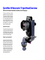
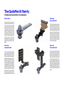
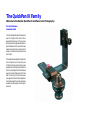
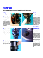
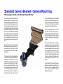
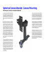
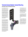
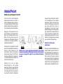
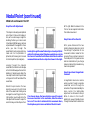
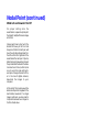
QuickPan III
Panoramic Tripod Head
User’s Guide - V0.9 - 27 June 2002
QuickPan III Panoramic Tripod Head Overview
Welcome to the Kaidan QuickPan III and Panoramic Photography
Thank you purchasing a Kaidan
QuickPan III Panoramic Tripod Head.
This manual is designed to help you
understand how to use your QuickPan
III to create quality panoramas. This
document will be revised from time to
time and updated versions can be
downloaded from the QuickPan III
page on the Kaidan web site.
QuickPan III Overview
The QuickPan III family is built around
a sturdy and precise Rotator Base with
interchangable indexing rings. There
are several camera brackets that slide
and lock onto the Rotator Base.
Why do I need a tripod head?
A panoramic tripod head makes it
possible to easily capture a sequence
of photos that are stitched to form a
complete panoramic image. It holds
the camera in the portrait orientation, positions the camera so that it
rotates around the optical center or
nodal point of the lens and provides
a repeatable and adjustable clickstop indexing mechanism.
The QuickPan III Family
Introducing the QuickPan III Components
Rotator Base
Standard
Camera Bracket
This heavy-duty design is lighter and more
compact than previous models and the competition. The new base employs interchangeable
Indexing Rings that support any number of
click-stop positions from 2 through 22. The
rings can be easily swapped at any time and
contribute to the light weight. The indexing
mechanism requires no lubrication or adjustments and has no loose parts.The base contains
an integral circular bubble level and
accomodates either 1/4” or 3/8” tripod threads.
The new QuickPan III Rotator Base will also accept older Kaidan camera brackets (i.e. KiWi+,
QuickPan).
The Standard Camera Bracket is designed to
support most digital and film cameras in a portrait orientation. Used primarily to shoot
single-row or cylindrical panoramas, the Standard Camera Bracket can be adjusted along the
horizontal arm of the Rotator Base in order to
locate the camera in the side-to-side orientation. There are three slots in the bracket, that
when used with various positioning aids, provide for the fore-aft adjustment of the camera's
optical center, or nodal point, over the rotational center of the tripod head.
Twin-Axis
Camera Bracket
Spherical
Camera Bracket
The Twin-Axis Camera Bracket is designed to
support most digital and film cameras that are
equipped with fisheye lenses, or for those users
who desire or appreciate two independent sliding and locking axes of adjustment. The two independent axes of adjustment positions the
lens in such a manner so as not to capture any
more of the Rotator Base than necessary. When
a camera equipped with a circular fisheye lens
is installed on the bracket, only a small segment
of the Rotator Base will appear in the image.
This feature makes the Twin-Axis Camera
Bracket ideal for those using iPIX software,
Panoweaver (www.easypano.net) and other
software applications that use fisheye images.
The Spherical Camera Bracket is designed to
support most digital and film cameras and to
permit the angular up/down elevation for the
capture of multirow spherical and QuickTime
VR Cubic panoramas. This bracket is ideal for
those software applications that stitch multiple rows of images, including up/down "cap"
shots such as REALVIZ Stitcher. The Spherical
Camera Bracket can also be positioned at a level
zero degrees, thus fulfilling the same functions
as the Standard Camera Bracket. An optional
Arca-Swiss Quick Release camera plate is also
available.
The QuickPan III Family
Welcome to the Kaidan QuickPan III and Panoramic Photography
Pro Quick Release
Camera Bracket
The Pro Quick Release Camera Bracket is designed to
support most digital and film cameras that are
equipped with fisheye lenses, or for those users who
desire or appreciate two independent sliding and locking axes of adjustment with the convenience of a quick
release mounting system. You can choose from either
a Bogen or a Arca-Swiss mounting plate (Arca-Swiss
shown at right).
The two independent axes of adjustment positions the
lens in such a manner so as not to capture any more
of the Rotator Base than necessary. When a camera
equipped with a circular fisheye lens is installed on the
bracket, only a small segment of the Rotator Base will
appear in the image. This feature makes this bracket
ideal for those using iPIX software, Panoweaver
(www.easypano.net) and other software applications
that use fisheye images. Of course, this bracket can also
be used with any wide-angle lens and stitching software as well.
Rotator Base
How to install and remove the indexing rings and adjusting the indexing force
Installing
Indexing Rings
Removing
Indexing Rings
1) Slide the Indexing Ring onto
On the lower portion of the black
Indexing Ring, there is gold colored pin visible through the hole
in the side. Insert the tip of a ball
point pen or a paper clip end into
the hole and push the gold pin inward till the Indexing Ring drops
down, then slide the Indexing
Ring off the Rotator Base.
the Rotator Base from the bottom, keeping the portion of the
Indexing Ring with the degree label facing up until it makes contact with the brass plunger. The
brass plunger will eventually snap
into the hole that in the side of
the Indexing Ring.
2) Rotate the Indexing Ring to
line up the notch on the top of the
Indexing Ring with the black
slanted alignment pin at the top
of the Rotator Base. The pin will
eventually go into the notch.
3) Depress the brass plunger and
push up on the Indexing Ring until the brass plunger pops into the
plunger hole and the pin slides
into the notch.
Adjusting the Force
of the Spring Plunger
The screw, shown at left, can be
used to position the spring
plunger up and down. You can use
a screwdriver (or a coin) to adjust
the indexing or click-stop force.
The spring plunger is set from the
factory, but you may find that you
prefer a harder click-stop action.
Be sure to not overtighten the
plunger so that the metal body of
the plunger would come in contact with the indexing ring. Also
be sure that the plunger is not set
deep enough as this will cause
excessive play in the indexing action.
Standard Camera Bracket - Camera Mounting
Mounting your camera on the Standard Camera Bracket
To mount your camera, first select the
appropriate slot in the Vertical Camera Bracket that will best locate the tripod mounting thread on your camera.
You may need to reposition the Captive Camera Knob. To remove the knob
simply slide it along the slot to the end
that has the threaded hole. Carefully
unscrew the knob out of the threaded
hole, being careful not to crossthread
the knob. Replace the knob into the appropriate slot by reversing the procedure.
Note: Whatever side of the Vertical
Bracket you mount your camera on always keep the offset portion of the
Vertical Bracket towards the rear of
the camera.
The camera knob is a two piece knob,
with a inner and outer knob. Before installing the camera knob in the Vertical Bracket, turn the inner knob clockwise into the outer knob until it won’t
turn anymore. Next install the knob
into the appropriate slot then into the
tripod mounting hole of your camera.
Turn the inner knob into the camera
until it bottoms out, then turn the
outer knob clockwise until the camera
is tight on the Vertical Bracket. Don’t
worry about getting the camera level
at this time, as this is a task you’ll need
to do when you’re ready to shoot.
The left-right adjustment to center
your lens over the pivot point is accomplished by loosening the purple
knob and sliding the bracket. Be sure
to tighten the knob to lock the bracket
in place.
The fore-aft adjustment is made by
loosening the camera knob and sliding the camera along the slot. There
are camera adjustment shoes and lugs
to locate your camera on the bracket
and to help position the camera along
the slot. These devices will also make
it easy to remove and replace your
camera when you use it for other
tasks.
Some models of the Standard Camera
Bracket may have the rubberized cork
as shown on the left. Newer models
have a special anodized coating that
will grip the camera.
Spherical Camera Bracket - Camera Mounting
Mounting your camera on the Spherical Bracket
The Spherical Camera Mounting Bracket
has a rotating swing arm which is held
into position by large black locking knob.
The knob allows you to position the arm
and your camera from plus 90° to minus
90°.
There are camera mounting shoes (flat
shaped) and lugs (triangle shaped) that are
provided for you to help locate and position
the camera. These are also helpful when
you want to remove and replace the camera and return it to the proper location.
Mounted on the swing arm is an adjustable camera mount. This mount can be
adjusted along the length of the swing
arm by loosening and tightening the
purple clamping knob. To remove the camera mount, simply loosen the knob and
slide the mount off of the swing arm.
There is a spring-loaded plastic ball which
provides drag on the camera mount as
well as the camera bracket. When you replace the mount or the camera bracket
onto their respective arms, you’ll need to
push it sharply so as to overcome the
spring force.
An optional camera mount is also available
with a quick-release mount. In this case you
would attach the a plate (either Arca-Swiss
or Begen) to your camera and this plate
would then dovetail into a mating plate on
the optional camera mount.
The standard camera mount (shown) has
a number of slots for you to choose from
to mount your camera. It’s important to
make sure that the centerline of your
camera’s lens intersects the pivot axis of
the swing arm. Since some cameras have
tripod mounting threads that are not
inline with the center of the camera, it may
be necessary to use one of the various slots
on the bracket.
Adjusting the camera position for the
nodal point is made by loosening the appropriate locking knobs and sliding either
the camera mount plate along the swing
arm, or sliding the entire assemblage along
the arm of the Rotator Base. Be sure to
tighten the knobs when you’re done positioning the camera.
Twin-Axis Camera Bracket - Camera Mounting
Mounting your camera on the Twin-Axis Camera Bracket
Select the appropriate slot in the
bracket that will best locate the tripod
mounting thread on your particular
camera. You may need to reposition
the camera knob to another slot in order to achieve this. To remove the knob
simply slide the knob along the slot to
the end that has the threaded hole.
Carefully unscrew the knob out of the
threaded hole, being careful not to
crossthread the knob. Replace the
knob into the appropriate slot by reversing the procedure.
The camera knob is a two piece knob,
with a inner and outer knob. Before installing the camera knob in the
bracket, turn the inner knob clockwise
into the outer knob until it won’t turn
anymore. Next install the knob into
the appropriate slot then into the tripod mounting hole of your camera.
Turn the inner knob into the camera
until it bottoms out, then turn the
outer knob clockwise until the camera
is tight on the bracket. Don’t worry
about getting the camera level at this
time, as this is a task you’ll need to do
when you’re ready to shoot.
The left-right adjustment to center
your lens over the pivot point is accomplished by loosening the purple knob
and sliding the camera bracket in and
out of the slider. Be sure to tighten the
knob to lock the bracket in place.
The fore-aft adjustment is made by
loosening the other purple knob on the
slider and then moving the entire assembly along the arm of the Rotator
Base.
There are camera adjustment shoes
and lugs (shown at left) to help locate
your camera on the bracket and to
help position the camera along the
slot. These devices will also make it
easy to remove and replace your camera when you use it for other tasks.
Nodal Point
What is it and how do I find it?
This is one of the most frequently
asked questions when it comes to
stitcher-based panorama creation.
Once you understand the basics, you’ll
be able to easily locate the nodal point
for any camera and lens combination.
how your finger moves with respect
to the background. This relative
movement is due to the fact that
you’re not rotating your head around
your eye’s nodal point, which is
somewhere in the center of your
eyeball. Instead, you’re rotating about
your spine which is several inches to
the rear and off to one side. It is this
relative side-to-side motion that we
will strive to eliminate when setting
up a camera for VR panoramas.
Simply put, the nodal point is the
point inside your camera where the
light rays converge and f lip over.
When shooting a panorama it’s
necessary to rotate about this point
to eliminate the image mismatch
caused by parallax error.
It’s also worth noting that the nodal
point is not the same as the film plane,
which is often marked on the
underneath side of many 35mm
cameras. Generally, for most 35mm
cameras and lenses, the nodal point
is located somewhere towards the
center of the lens barrel.
Parallax error can be easily
demonstrated by this simple
experiment. Close one eye and hold
your index finger upright about six
inches away from your open eye. Rock
your head from side to side. Notice
Step 1: The side-to-side
adjustment
Parallax error can be easily demonstrated. It’s the relative
movement caused by a shifting point of view. In this example,
you eye is moving with respect to your hand and the background.
Once your camera is fastened to your
camera bracket, move to the front of
the tripod head so you’re looking into
the lens. Adjust the camera bracket so
that the center of the lens is directly
over the pivot axis of the tripod head.
Try to be as accurate as possible. You
should strive to get this adjustment
within plus/minus a 1/16th of an inch.
Nodal Point (continued)
What is it and how do I find it?
Step 2: Fore-Aft Adjustment
left to right. Slide the camera to the
front or rear as required to eliminate
This step is most easily accomplished
out of doors. Find a vertical edge or
line, such as a doorway or edge of a
building. Position your camera and
tripod about 2-1/2 feet away, or as close
as possible with the edge still in focus
when you look through the
viewfinder. If you’re using a multirow
head such as the QuickPan III
Spherical, set the swing arm to a level
horizontal position (zero degrees).
this relative movement.
Step 3: Record Your Results
Looking through the viewfinder align a close object (brick
wall) with a faraway object (telephone pole). As you rotate
the camera from side-to-side there should be no relative
movement between the two objects as shown to the right.
Looking through the camera’s
viewfinder, find another vertical edge
or line that is far away, such as another
building or telephone pole. Align the
two objects and rotate the pan head
so they are in the left hand side of the
viewfinder.
Rotate the pan head so the two
objects move over to the right hand
side of the viewfinder. Unless you’ve
managed to unwittingly locate the
right position, you should notice the
two objects will move with respect to
each other as you rotate the pan from
After you’ve discovered the two
location dimensions, be sure to record
the settings. The QuickPan III has
convenient indicator scales for this
purpose. These numbers represent
the nodal point for this given camera
and lens combination. If you change
cameras or lenses, this procedure may
have to be repeated
Step 5: How About Rangefinder
Cameras?
If, as shown above, the two objects move with respect
to one and another in the viewinder, slide the camera
fore or aft in order to eliminate this movement. Here,
the telephone pole has moved behind the brick wall.
A rangefinder camera is a camera
where you look through a separate
viewfinder and not through the
actual lens. The process is basically the
same. Locate the Side-to-Side
adjustment as discussed in Step 1.
When it comes to the Fore-Aft
adjustment, you won’t be able to look
through the viewfinder to determine
Nodal Point (continued)
What is it and how do I find it?
the proper setting since the
viewfinder is a separate optical path
that doesn’t really “see” the same image
as the film.
Instead, you’ll have to start with the
bracket all the way to the front and
take pairs of test shots. Each pair will
have the vertically aligned objects in
the left and then the right side of the
viewfinder. After each pair of photos,
slide the bracket rearward and repeat
the process. Slide the bracket the same
increment each time (i.e. 10mm). Be
sure to record the scale setting for
each pair of images. Process the film,
or in the case of digital cameras,
download the images to your
computer.
At the end of this process you will be
able locate the pair of images with the
least relative movement. If no single
image is optimum, you may need to
interpolate between two images to
find the closest value.
Shooting Panoramas
How do I begin?
How much Overlap?
Taking the Photos
The amount you turn the camera for each shot
varies. It is dependent on a number of factors
such as the field of view (the angle) of your
camera and lens, as well as which program you
intend to use. For example, in their QuickTime
VR Authoring Studio, Apple recommended that
the images should overlap by anywhere from
one-third to one-half. That’s a good rule of
thumb for most stitching applications. You
should check with the recommendations of the
software that you intend to use in order to
determine overlap requirements.
When you’re ready to shoot, make sure that the
camera is securely attached to the QuickPan III.
You should use a tripod that is sturdy, ideally
one that has a center support system of braces
to help keep the camera from flexing.
How many Shots?
Once you’ve determined the overlap, you’ll be
able to figure out how many shots. The easiest
way to do this is to simply look through the
viewfinder and turn the camera to achieve the
desired amount of overlap. You then check the
angle readout to see how far you turned the
camera. Round the angular value to the nearest
convenient value. For most stitching programs,
it is generally not that important to use a
precise overlap value. However, it should be
noted that some programs are more sensitive
to an overlap value that constantly repeats
from shot to shot. You may need to experiment
somewhat to obtain the best results.
Proper leveling is important and often
misunderstood. When it comes to leveling there
are two things that are fairly important. With
multirow panoramas (i.e. Stitcher) the issue of
leveling is less crucial and primarily involves
aestethics and placement of the horizon. We’ll
concentrate primarily on cylindrical or singlerow panoramas.
First, the camera's optical axis should be parallel
with the rotation plane of the tripod head. In
other words the camera should not be pointed
up or down with respect to the plane of
rotation.
Secondly, it's also somewhat important for the
camera and film/CCD to be properly aligned
with respect to rotation when viewed from the
front (looking into the lens).
This can happen because the camera is not
seated flush against the upright bracket. This
is pretty common since many cameras have
mounting screws that are not in the center of
the base. Many cameras have screws off to one
end of the camera or at the edge of the camera
and this can cause the camera to not be pulled
down evenly onto the tripod head mounting
plate.
Another problem is that CCDs may not be
accurately positioned within the camera body
and respect to the mounting surface. It only
takes a fraction of degree and with other
manufacturing tolerances this can add up to be
noticeable.
This misalignment can also happen if the
upright bracket is bent or is not exactly
perpendicular to the rotation plane of the head.
At Kaidan we check this dimension very closely
to ensure it's as close to 90°as reasonbly possible.
The effect of a rotated camera (when viewed
looking into the lens) is a stairstepping of
images as you progress around the panorama.
Stairstepping has nothing to do with the state
of the entire head being level with respect to
the horizon. This can be corrected by rotating
all the images a slight amount in your authoring
program.
Shooting Panoramas (continued)
How do I begin?
You can also shim the camera/head to
compensate for such misalignment errors as
well. A few layers of tape is usually all that it
takes. Let me also reiterate what's not as
important as some people think.
The overall level of the head/camera is not as
critical in order to produce good stitched
results. As long as the camera is not tilted or
rotated and as long as the camera is positioned
so that the optical axis is parallel to the rotation
plane, you can tilt or position the entire head
so that it's not level to the horizon and it won't
affect the image.
Now, it might produce a panorama that is tilted
with respect to the horizon but that might be
an artistic choice or something you want to do
on purpose.
As long as the optical axis is parallel to the
rotation plane and the camera/CCD is not
rotated, slight variations in level as the head
rotates is generally not a problem.
As you shoot around the circle, try to avoid
capturing any moving objects that might come
into your field of view. There is no harm in
waiting, for example, while a person walks past
before shooting the photo.
You may also want to check with the software
developer of the stitching software that you’re
using to get their recommendations for
exposure settings and other camera settings.
We hope you enjoy shooting your panoramas
and if you have any questions or problems using
our equipment, please let us know.
Warranty and Product Return Information
Copyright © 2002 Kaidan, Inc. All Rights Reserved. First Edition, June 2002. QuickPan is
a trademark of Kaidan, Inc. Other products mentioned herein may be trademarks of
their respective companies. Patents Pending.
Information in this manual is subject to change without notice and does not represent
a commitment on the part of Kaidan. No part of this manual may be reproduced or
transmitted in any form or by any means, electronic or mechanical, including photocopying, recording, or information storage and retrieval systems, or translated to another language, for any purpose other than the licensee’s personal use and as specifically allowed in the licensing agreement, without the express written permission of
Kaidan.
Kaidan Warranty and Return Policy
A • Limited Warranty
In the event of a defect in materials or workmanship, Kaidan will repair the product
with new or rebuilt parts for a period of three-hundred and sixty five (365) days from
the date of original purchase. Such work will be performed free of charge. Follow the
Product Return Procedure (Section D following). Likewise, any software purchased from
Kaidan also comes with a one year warranty if your disc or media is defective or damaged. This warranty is extended only to the original purchaser and is not transferable.
A purchase receipt or other proof of original purchase will be required before warranty
performance is rendered. This warranty only covers failures due to defects in materials or workmanship which occur during normal use. It does not cover damages or failures which are caused from accident, misuse, abuse, neglect, mishandling, misapplication, alteration, faulty installation, modification, service by anyone other than an authorized representative of Kaidan, Acts of God, or by products not supplied by Kaidan.
This warranty covers any damage incurred during original shipment of product to customer. Any item resold, or distributed by, and not explicitly manufactured by Kaidan
will be covered by their respective company’s product warranty.
B • Warranty Exclusions
or limitations may not apply to you. This warranty and any claims which arise with the
Kaidan product(s) are governed by the laws of the state of Pennsylvania. By purchasing
this product, customer acknowledges and agrees to these Limits and Exclusions. If a
problem with your Kaidan product develops during the warranty period, immediately
contact Kaidan for assistance.
C • Product Return Policy
All Kaidan products come with a 30-day return policy (a minimum 10 percent restocking fees may apply) from date of purchase, with the exception of software or videotapes. Both of the aforementioned items are copyrighted and subject to the laws concerning intellectual property. Kaidan will replace defective software/videotapes free
of charge upon return receipt of defective item(s). Products returned under this policy,
excluding replacement of defective items, must be shipped at purchaser’s expense. Purchaser must ship product with an approved traceable service, such as FedEx, and with
appropriate levels of shipping insurance for the item being returned. Kaidan will not
be held responsible for returned items lost or damaged in transit. Kaidan will issue a
refund to customer’s account if the following conditions are satisfied:
Items Part of Special Bundle
If item(s) are part of a special bundle offer, return of part of the bundle will void any
special pricing and the item(s) remaining in the possession of the customer will revert
to their regular Suggested Retail Price (SRP). The credit, to customer, will reflect the
difference of the actual product SRP from the amount of credit due customer.
Shipping Costs
All shipping costs, VAT, duties and return costs are sole responsibility of customer. If
customer purchases thru Kaidan distributor or reseller, customer is responsible for all
shipping and VAT costs incurred by that distributor or reseller. These charges are nonrefundable. For instructions on the return of your product, follow the Product Return
Procedure below
D • Product Return Procedure
1) Receipt of item(s) in a restockable condition.
• All parts are included in box; hardware, manuals, discs, nuts/bolts, tools.
• No signs of damage; scratches, bent parts, missing pieces, markings, alterations, or additions to the product.
• All packaging materials are intact; foam, peanuts, cardboard, bubble bags.
• No signs of excess usage or wear to the product.
When returning a product, customer must first contact Kaidan (or the distributor/
reseller) and obtain a Return Material Authorization Number (RMA#). After receiving
the RMA#, customer will be instructed to return product directly to Kaidan. Returned
goods must be shipped with an approved traceable service, such as FedEx, and with appropriate levels of shipping insurance for the item being returned. Kaidan will not be
held responsible for returned items lost or damaged in transit. RMA numbers are valid
for 15 days, and the product(s) must be received by Kaidan before the RMA expires. We
are unable to accept for return any product(s) received after the expiration of the RMA.
Items of Non-Restockable Condition are subject to the following:
Return Packaging
• Restocking Fee(s) - a minimum of 10% and possible additional fees based on the condition of the product (how the product best meets the criteria above), at Kaidan’s discretion.
The product packaging must reflect customer name, address, RMA# as well as Kaidan
information:
Criteria for Restockable Condition is as follows:
There are no express warranties except as listed above.
Non-Restockable Condition - constitutes the following:
Kaidan shall not be liable for special, incidental, consequential or punitive damages, including, without limitation, loss of goodwill, profits or revenue, loss of the use of this
product or any associated equipment, cost of substitute equipment, downtime costs,
or claims of any party dealing with buyer for such damages,resulting from use of this
product or arising from breach of warranty or contract, negligance, or any other legal
theory . All express and implied warranties, including the warranties of merchantability and fitness for a particular purpose, are limited to the applicable warranty period
set forth above. Some states do not allow the exclusion or limitation of consequential
damages, or limitations on how long an implied warranty lasts, so the above exclusions
• If damages occur in shipping, customer must submit claim with shipping company
prior to any action by Kaidan.
• Missing parts; hardware, manuals, discs, nuts/bolts, tools, and packaging materials;
foam, peanuts, cardboard, bubble bags.
• Signs of damage; scratches, bent parts, missing pieces, markings, alterations, additions
to the product.
• Signs of excess usage or wear to the product.
• Damage or loss incurred during uninsured shipping to Kaidan. In this case, Kaidan
cannot issue any type of refund. Customer will be responsible to submit claim with their
shipping company.
Kaidan Incorporated
703 E. Pennsylvania Blvd • Feasterville, PA 19053 • U.S.A.
Attention: Return Department per RMA# ______
Contact Information: Voice: 215-364-1778 • Fax: 215-322-4186
http://www.kaidan.com • E-mail: [email protected]