1
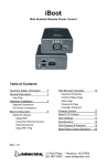
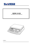
K3 Series
1U Rack Mount A/B Switches
General Description
The K3 Series A/B Switching system provide up to 3 AB switches in a 1.75 in rack mount chassis for 19”
Equipment cabinets. Each switch allows a common circuit (COM) to be switched to either of two circuits,
designated A and B. The switches can be controlled locally with a front panel toggle switch and remotely
by; contact closure, or thru a Serial port and Ethernet connection using Telnet, SNMP, or a Web browser.
Modular System
The K3 System consists of the K3 Chassis, Model K3-R and Power, Control and A/B Switch options.
The following table illustrates the available K3 components available at the time of printing. Additional
options may be available; contact Dataprobe.
SKU
Model
Description
Base
1150100
K3-R
K3 Chassis
Control
1340062
C-AB-16-R
IP and Serial Control Card, Individual Switch Control
1340065
C-AB-1-R
IP Control Card, Gang Control
1340063
G-AB-1-R
Gang Expansion or GPI Control
1930077
PS-R1-WRI
Internal AC Power Supply 100-240VAC
1930078
PS-R1-48
Internal -48VDC Power Supply
1930079
PS-R1-224
Dual External 24VDC Power Supply. For use with External AC Supply
1930076
PS-WRI-4
External A/C Power Supply
1110100
AB-R-D25
25 Pin D Subminiature, all 25 pins supported
1110101
AB-R-RJ8
8 Wire Modular Jacks; All leads switched. Supports RJ48C, RJ48S, RJ45 and
all 8 position modular jack specifications, up to16Mhz
1110102
AB-R-2RJ8
Same as above with two ganged switches.
1110103
AB-R-NET
8 Position, 8 Wire Modular Jacks; All leads switched; Supports 10/100/1G
Ethernet Network specifications.
1110104
AB-R-T50
50 Pin Telco (Amphenol) connector. All 50 Leads Switched. Dual Height
Switch must be in Slot 1
1110105
AB-R-M34
34 Pin M Type (V.35) connector. 23 leads switched. Dual Height Switch must
be in Slot 1
1920028
AB-FP
Blank Panel for unused A/B Slots. Required for FCC and CE marking
Power
A/B
K3_system_v070607e
Technical Support: 201-934-5111
Main: 201-934-9944
[email protected]
Website: dataprobe.com
K3 System
Page 2
Installation & Operation
K3 Chassis
The K3 Chassis holds the Power, Control and A/B Switch modules for the K3 system. It installs in a
standard 19” EIA equipment cabinet, requiring 1.75” (1U) of rack height. K3 systems are preconfigured
and tested in the factory. All Control, Power and Switch modules are pre-installed.
Manual Switch Control
A front panel momentary toggle switch for each A/B Switch installed allows local manual control.
AB Switch Status Indication
Two front panel LED's for each A/B Switch installed indicates switch position A or B.
Individual switch status can also be monitored thru the Network or Contact control interface.
Remote alarms or displays can be controlled by the status signal of each switch, which are provided as
form C relay contacts when the Contact interface is installed.
Power Supply Status Indication
The K3 has two LED indicators that display the current status of two power supply sources. These are
designated PS-1 and PS-2. LED ON Indicates the power supply source is connected.
PS-1 Internal Power Supply Module, or External Power Supply #1
PS-2 External Power Supply #2
K3 System
Page 3
The K3 series supports both internal and external power supplies. Internal power modules are available
to support worldwide A/C power, -48VDC and +24VDC power requirements. External power supplies
provide redundancy either when used in pairs, or when combined with an internal module.
Power Supplies Modules
The K3 Series can be powered by several types of power sources using four types of power supply
options; 90- 240VAC 50/60Hz Internal module, 90 -240 VAC External module, 48 VDC Internal module
and 24 VDC direct.
Combinations of 1 internal + 1 external supply or 2 external supplies can be used for redundant power
applications.
Dataprobe offers the following internal supply modules for the K-16 series:
193007
7
PS-R1-WRI
Internal AC Power Supply 100-240VAC
193007
8
PS-R1-48
Internal -48VDC Power Supply
193007
9
PS-R1-224
Dual External 24VDC Power. For use with External AC Supply
Power Supply 1930077
Power Supply 1930078
Converts 110/ 220 /240 VAC to 24VDC
Single Slot Redundant Capable
Converts 48 VDC to 24VDC
Single Slot Dual Redundant Capable
Input Power
Nominal : 120/240 VAC 50/60 Hz
Range : 100 - 240 VAC
Watts: 50
Fusing: 2 A
Input Power
100 - 240 VAC
1.4A, 50-60 HZ
ALARM
Environmental
Operating: 0 C - +65C
!
REFER TO MANUAL
Nominal : 48 VDC
Range : 42 - 60 VDC
Watts: 75
Fusing: 2.5 A
INPUT
48VDC, 2A. MAX
ALARM
Environmental
Operating: 0 C - +65C
Physical
Physical
AC Input connector:
IEC 320 (C14) on rear panel
DC Input Connector:
Screw Terminal Mating Connector Supplied.
Alarm / Expansion connector: 9 pin d-Sub
Contact Ratings: 1A @ 24VDC res.
Alarm / Expansion connector: 9 pin d-Sub
Contact Ratings: 1A @ 24VDC res.
K3 1RU AB Switch
Page 4
Alarm Connector
Alarm Connection on each power supply provides status information on the condition of the supply.
9 Pin Dsubminiature
Pin 6 NO
Pin 7 COM
Pin 8 NC
Pin 6 shorts to Pin 7 when the Power Supply is Non-Operational
Pin 8 shorts to Pin 7 when the Power Supply is Operational
Power Access Panel 1930079
Provides for connection of two
K-16-XPS Power Supplies
Input Power
Nominal : 24VDC
Range : 20 – 30 VDC
Fusing: 2 A Slo-Blo
Physical
DC Input Connector:
Connector: Molex 41995
Mating Connector Kit # 1940164
Mating cable supplied with K-16-XPS
PS1
PS2
K3 24VDC External PS Panel
Rear View
External Power Supplies 1930076
Power Input 100-120/200-240 50-60Hz IEC320 Male.
Power Input cord supplied for North America.
Power Output +24VDC 4.5A, Connector Molex 41995.
6
5
4
3 2
1
1, 2 +24VDC
5, 6 GND
3, 4 N.C.
K3 1RU AB Switch
Page 5
Control Modules
The K3 Series AB Switch System is available with three types of control modules; Network, Contact
Closure, or Gang Control Expansion. One of three control options shown below will be installed in the
chassis for remote control of the installed AB switch cards.
C-AB-16-R
C-AB-16-R provides remote control through In-Band and Out-of-Band operation thru
Ethernet TCP/IP and Serial connections.
WEB
Telnet
SNMP
Serial
TCP Messaging
Through a web browser interface, you can access the control card, obtain
current status information and operate the A/B Switches
Through a telnet client, you can access the control card, obtain current
status information and operate the A/B Switches. This is also the method
for setting configuration parameters of the card
The system can be managed by SNMP through standard management
software. Dataprobe provides a private MIB.
The serial port on the C-AB-16-R provides direct terminal access or via
modem. The A/B Cards are controlled either by a menu selection or by
command line strings (escape code sequences). Menu selections are ideal
for easy operator interface and the escape code sequences streamline
automated control.
A direct TCP messaging protocol is supported for direct computer
control of the A/B switching system
Installation
The Control interface is located in the lower middle section on the rear of the K3 chassis.
The C-AB-16-R controller provides the following connections:
10base-T Ethernet. (C-AB-16-R
only) Network connection for access
to the C-AB-16-R card.
C-AB-16-R Rear View
Serial Port. RS-232 port for out-ofband access to the
C-AB-16-R
card.
Gang Expansion. RJ11 connection
for connection to additional card nests
for large gang switching applications.
External Power Input. Connection for
external power supply K-16-XPS-R for
single or dual redundant power.
Mating Connector kit # 1940164
Gang
10base-T
Ethernet
Serial Port
PS2
External 24VDC
Gang
Expansion Power Input
(optional)
K3 1RU AB Switch
Page 6
Serial Port
The Serial Port on the control card is a 9 pin male connector, configured as a DTE. The following pins
are used. The following chart illustrates the pin out of the D9 connector and the connection required to
an external modem with a D25 pinout.
D9 Pin
Abbreviation
Full Name
Modem
D25 Pin
Pin 2
RD
Receive Data
Pin 3
Pin 3
TD
Transmit Data
Pin 2
Pin 5
SG
Signal Ground
Pin 7
Pin 9
RI
Ring Indicator
Pin 22
For connection directly to a terminal, a Null Modem cable is required.
C-AB-16-R
D9 Pin
Terminal
D9 Pin
Pin 3
Pin 2
Pin 2
Pin 3
Pin 5
Pin 5
Configuration – C-AB-16-R
Configuration of the The C-AB-16-R involves the following steps:
• Setting The C-AB-16-R 's IP Address
• Setting additional configuration parameters using Telnet
Setting I/P Address
The C-AB-16-R comes with factory installed IP address 192.168.1.254. In most cases this will need to
be changed.
Consult your Network Administrator to determine the appropriate IP address. There are several methods
to change the IP address.
• ARP
• Telnet
• Serial Port
• setip.exe program, available from Dataprobe’s web site
To set the IP address, the hardware (MAC) address must be known. This address is located on a label
on on the C-AB-16-R printed circuit board. The syntax for the MAC address is: nn-nn-nn-nn-nn-nn
K3 1RU AB Switch
Page 7
Setting the IP address using ARP
To set the IP address using ARP, connect the jack marked 10Base-T to your local Ethernet network and
apply power to the unit. The computer used to set the IP address must be on the same physical network
as the C-AB-16-R . ARP does not work across switched or routed networks.
Windows (98 and Later)
1. Open a DOS window.
2. Type the following command:
arp -s <IP Address> <MAC Address>
Where <IP Address> is the desired IP address (in dotted decimal) for the C-AB-16-R and the <MAC
address> is the MAC Address of the C-AB-16-R . The MAC Address is located on a label on the rear
panel of the card.
Example: arp -s 63.211.86.165 00-50-c2-05-01-c1 <enter>
|--- new IP addr. ---| |------- MAC addr. ------|
3. Ping the C-AB-16-R to program the IP address into the C-AB-16-R .
Type: ping <IP Address>
If the ping command returns “host not responding” 4 times then the address has not been
programmed properly, or the IP or MAC Address is incorrect. In either case redo step 2. If the
problem persists, contact the Dataprobe Tech Support Hot Line.
4. Delete the entry from the ARP cache by typing:
arp -d <IP Address>
5. Ping the C-AB-16-R to confirm that it has been programmed.
If the card fails to respond, repeat steps 2-4 above. If the problem persists contact the
Dataprobe support hotline.
Unix, Linux
Consult your systems administrator for information on setting an IP Address using ARP. The unit should
be pinged after the IP Address has been set to confirm proper operation.
Setting IP Address with Telnet
For initial setup, the computer used must use the same network segment as the default IP Address, or
current IP address. (192.168.1.xxx) If this is not the case, use one of the other methods. To connect to
the C-AB-16-R using telnet, run your telnet client program (provided with your operating system) and
connect to the IP address as set in step one above.
For Windows:
Select Run…Telnet
Connect…192.168.1.254
(or the current IP address)
As soon as you connect the following message will be displayed:
K-16
Ver 4.00
Please Enter The Password
Password >
The factory default password is:
PASS
K3 1RU AB Switch
Page 8
This password is case sensitive and can be changed in the setup process. In telnet, the The C-AB-16-R
has a security timeout feature. After 2 minutes of no activity, The C-AB-16-R will automatically
terminate the session. Should this occur, simply re-connect and re-enter the password.
K-16
Set Location
1. New York 1
2. New York 2
3. Philadelphia
4.
5.
6.
7.
8.
9.
10.
11.
12.
13.
14.
15.
16.
A
B
A
A
A
A
A
A
A
A
A
A
A
A
A
1-16. Operate Switch
A. All to 'A' B. All to 'B'
S. Setup
X. Exit
K-16> S
Select S to access the setup Menu
K-16
1.
2.
3.
4.
5.
6.
X.
Set Location
Location Name
Card Setup
Password
Com Port
Escape Response
IP Settings
Exit
K-16>
Setup Menu
Set Location
9600 8n1
No
K3 1RU AB Switch
Page 9
Select 6 for IP Settings. The IP Settings Menu appears:
IP Settings
1.
2.
3.
4.
5.
6.
7.
8.
9.
A.
B.
C.
D.
X.
IP Address
Subnet
Gateway
Web Port
Telnet Port
Message Port
MTU
Write Community Name
Read Community Name
SNMP Manager 1
SNMP Manager 2
SNMP Manager 3
SNMP Manager 4
Exit
192.168.1.42
255.255.255.0
0.0.0.0
80
23
9100
1024
private
public
192.168.1.97
0.0.0.0
0.0.0.0
0.0.0.0
K-16>
Enter the IP address, Subnet Mask and Gateway in Dotted Decimal Format.
Setting IP address via Serial Port
The serial port uses the same menu sequences as the Telnet method described above. Connect a
terminal directly to the C-AB-16-R serial port. Send an Enter keystroke to start the session. The serial
port default settings are 9600bps, 8 data bits, no parity, one stop bit. These setting can also be changed
via the menus.
Setting IP Address with setip.exe
Utility setip.exe is available from Dataprobe’s website at http://www.dataprobe.com/files/control/setip.exe.
Download this windows program and run it on any computer on the same physical network segment as
the control card. Enter the MAC address and desired IP address and press SetIP.
Setting other Parameters
Via the Serial Port (or telnet on the C-AB-16-R) , all other configuration parameters can be set for the CAB-16-R . These setting are made from the Setup Menu, as described in the section 3.1.3 above.
Location Name: Enter a 1-20 character name to identify the system. This name appears at the top of
each telnet screen and web page.
Card Setup: This allows setting of parameters for individual A/B cards in the system. Each card can be
named, up to 20 characters, and can be enabled or disabled. Disabling a card hides its status from web
and telnet screens. This should be used where no card is installed, to make reading the screens easier.
NOTE: Only the 1st three AB card slot positions of the 16 displayed are used in the K3. Displayed
Slots 4 thru 16 are non functional.
Password: A password from 1 to 15 characters is needed for access to the system. Re-enter the old
password then enter the new password twice as prompted.
K3 1RU AB Switch
Page 10
Com Port: Set the Baud Rate and Character Format for the serial port. Baud rate choices are 9600,
19200, and 38400. Character format choices are 8N1, 7E1 and 7O1 (databits, parity, stop bit).
The Default Serial Port Parameters are 9600, 8 Data Bits, No Parity, One Stop Bit (9600,8,N,1)
Escape Response: This selects Yes or No for escape code responses. See section 3.4.3 on escape
code control
IP Settings
IP Settings
1.
2.
3.
4.
5.
6.
7.
8.
9.
A.
B.
C.
D.
X.
IP Address
Subnet
Gateway
Web Port
Telnet Port
Message Port
MTU
Write Community Name
Read Community Name
SNMP Manager 1
SNMP Manager 2
SNMP Manager 3
SNMP Manager 4
Exit
192.168.1.254
255.255.255.0
0.0.0.0
80
23
9100
1024
private
public
0.0.0.0
0.0.0.0
0.0.0.0
0.0.0.0
K-16>
IP Address, Subnet Mask and Gateway: Enter the appropriate information in dotted decimal format
(xxx.xxx.xxx.xxx). If you are unsure of the entries, consult your network administrator.
Web Port, Telnet Port, Message Port: These three settings determine the port assignment for the
different TCP protocols used to communicate with the control card. Standard port assignments for these
protocols are:
WEB: 80
Telnet: 23
Message: 9100
If you change these assignments, you will need to specify them when you connect to the C-AB-16-R .
For example if the IP address of the C-AB-16-R is 192.168.1.254 and you have changed the web port to
8800, then you would need the following URL to access the C-AB-16-R : http://192.168.1.254:8800
K3 1RU AB Switch
Page 11
Note: After changing the IP Address, Web Port, Telnet Port or Com Port parameters, it is
necessary to reboot the C-AB-16-R. By removing power to the the K3 chassis momentarily and
then reconnecting the power source. Neither operation will alter the switch positions of any A/B
Card in the Nest.
MTU: Maximum Transmission Unit. Set the MTU from 100 to 1024. The default of 1024 should not be
changed unless required by network architecture.
Read and Write Community Names: These settings are for use with SNMP managers only. Set the
names as appropriate for your SNMP configuration.
SNMP Managers: Set up to four SNMP managers that will receive SNMP TRAPs. Other SNMP
managers will be able to manage the system.
Operation
Remote control of each or all A/B Cards is accomplished using either TCP/IP protocols for Web browser
(http) , Telnet, or direct TCP messaging. Each card in the chassis can be operated independently, or all
3 A/B cards can be operated simultaneously. In all cases, switch control is password protected.
Web Browser Operation
To access the K3 using any web
browser, point your browser to the IP
address of the C-AB-16-R card. If the
IP address is the default 192.168.1.254
then enter in the web browser address
bar: http://192.168.1.254
You may wish to bookmark this location
and rename the bookmark for easy
reference.
You will be prompted for a User Name
and Password. The User Name is not
used, and any or no characters can be
entered there.
Enter Password as programmed in the setup menu system. The default password is PASS. Please
guard your password safely. If the password is forgotten, contact Dataprobe Tech Support.
Upon entering the correct password, the main page will be displayed.
K3 1RU AB Switch
Page 12
The web page shows the current status of each enabled card in the chassis. It also displays the status of
the two power supplies in the lower right corner.
To operate one or more switch cards: Select the desired A/B Card(s) using the checkbox next to the
card and then click on the large A or B button under Switch Control. The screen will refresh with the new
card status shown. Buttons for Select All and Select None assist in making selections.
The Web page will not automatically refresh if the A/B cards are controlled using the manual switches. In
the event that switch cards are operated by front panel toggle switches or other external control, a
Refresh button is provided. Click on this button to view the most current status information.
K3 1RU AB Switch
Page 13
If cards are not installed in the system, their status will be reported as Position A. To avoid confusion,
use the Disable feature in the Telnet Setup for unused card slots. When cards are disabled, their name
will continue to appear on the web page or telnet screen, however, their status will be indicated as
displayed in the screenshot below. Note: Card 4 – 16 are not available in the K3 system and have been
disabled.
To simultaneously switch all cards in the chassis, click on either the Gang A or Gang B buttons. The
checkboxes need not be used for this operation.
K3 1RU AB Switch
Page 14
A logout button is provided. Click this button to be instantly logged out. There is an automatic logout
function if there is no activity for two minutes. You can also just close the browser; however you will not
be able to log back in for two minutes.
Telnet and Serial Port
The menu system of the C-AB-16-R is the same for Telnet and direct serial access.
For Telnet: Enter the IP address of the C-AB-16-R into your Telnet application program
For Serial Direct Terminal Connection: press the Enter Key
For Serial Connection via Dial-up Modem: Establish the dial link, then press the Enter Key.
After entering the correct password, the main screen is displayed
K-16
1.
2.
3.
4.
5.
6.
7.
8.
9.
10.
11.
12.
13.
14.
15.
16.
Set Location
New York 1
New York 2
Philadelphia
Baltimore
Atlanta
Charlotte
Tampa
Chicago
Cleveland
St. Louis
Minneapolis
Dallas
Seattle
Portland
San Francisco
Los Angeles
A
B
A
A
A
A
A
A
A
A
A
A
A
A
A
A
1-16. Operate Switch
A. All to 'A' B. All to 'B'
S. Setup
X. Exit
K-16>
The screen shows all enabled cards and their current position A or B
Enter any card number 1-3 to operate that card; A or B to switch all cards to that position.
Enter S to access the setup menus (see section 3.2.5 for setup details)
Enter X to logout of Telnet.
Card slots that have been disabled will not report any status.
NOTE: Only the 1st three AB card slot positions of the 16 displayed are used in the K3. Displayed
Slots 4 thru 16 are non functional.
K3 1RU AB Switch
Page 15
SNMP Manager Control
The C-AB-16-R allows for management via SNMP. The private MIB is available from the Dataprobe
Web Site at: http://www.dataprobe.com/files/switch/k16/k16.mib
MIB Outline and MIB Definitions can be found in Appendix A.
Command Line and Direct TCP Messaging
The C-AB-16-R can be controlled via command line messages sent either over the serial port or using
TCP messaging over the Ethernet port. This allows streamlined communication between the C-AB-16-R
and network management systems or computer based monitor and control systems. Programming
support is available. Contact Dataprobe Applications Engineering.
Making Connection via Ethernet and Serial
The C-AB-16-R uses the TCP (Transport Communication Protocol) to communicate with the client PC.
To use the C-AB-16-R , establish a TCP connection (Stream Socket) to the C-AB-16-R . Be sure to use
the Port assigned to the C-AB-16-R , either Port 9100 or the port assigned through the Setup Menus.
Once connected use the Send() function to send the commands to the C-AB-16-R and the Recv()
function to receive the C-AB-16-R ’s response.
For the CP-K16-R or the serial port of the C-AB-16-R , connection via the serial port requires only setting
the computer to the proper baud rate and character format.
Command Syntax
<esc><password><^a><card><^b><command><cr>
Where:
esc
password
^a
card
^b
command
=
=
=
=
=
=
cr
=
The ASCII escape character (0x1b)
The C-AB-16-R password in ASCII (case sensitive)
The ASCII control 'a' character (0x01)
The number of the card to be changed, with or with out leading 0's (a or A = all)
The ASCII control 'b' character (0x02)
The command to be executed:
a or A - Switch selected card to A
b or B - Switch selected card to B
q or Q - Display the status of the selected card
The ASCII Carriage Return (0x0d)
The < and > in the syntax above are only to delineate the control characters and should not be sent.
Example: To switch card 7 to B send <esc>PASS<^a>7<^b>B<cr>
Response Syntax
The syntax for the command response is.
<card><status><cr>
Example: 01A
card
status
=
=
The number of the card.
The status of the card either A, or B.
K3 1RU AB Switch
Page 16
cr
=
The ASCII carriage return character
If the queried card has been disabled then no response will be transmited.
In response to the Query All command, 16 response messages will be sent.
All invalid commands will be ignored. No response even when responses are enabled.
Gang Control Expansion
G-AB-1RR Gang Expansion Card
The G-AB-1RGang Expansion Card provides input and output of gang control, allowing for simultaneous
switching of multi-chassis systems. Connection is also provided for external power input from the K16XPS or similar +24VDC source.
Installation
The Gang Expansion interface is located in the lower middle section on the rear of the K3 chassis.
Connection between G-K16X units or connection from C-AB-16-R or other control card is made using 6
wire connection modular jack cords. ( RJ11 / RJ12 type )
Expansion Connector Pinout
Pin
Designation
1 & 6 Ground
2 & 5 Switch to B
3 & 4 Switch to A
Gang Out Gang In
Alarm
G-K16x Rear View
To control the system, momentarily short either Switch to A or Switch to B to Ground.
PS2
K3 1RU AB Switch
Page 17
A/B Switch Modules
The K3 Rack Mount AB Switching System can be factory configured with up to 3 AB switches of any of
the following interfaces plus one control interface and power supply configuration. Some switch
interfaces occupy 2 slots – SW1 & SW2
Frame Ground Switching
1
(D9, 15 and 25 model Only)
Jumper selection allows Pin 1 Frame
Ground to be either switched or tied
together and unswitched. Pin 1 can also
be tied to the Frame of the Chassis, or left
isolated from the chassis.
Signal Ground Switching
(D9, 15 and 25 model Only)
SW'D
FG
COM
ISO
1
1
A
B
COM
Shown In Factory Default:
Ground Switched & Isolated
An additional set of jumpers provides the
same switched/common, isolated or grounded for Signal Ground. These jumpers control Pin 7 in the
D25 model and Pin 5 in the D15 and D9 models. The circuit is the same as shown above replacing Pin
1 for the correct pin and SG Signal Ground for FG, Frame Ground
Signal Ground Switching
An additional set of jumpers provides the same switched/common, isolated or grounded for Signal
Ground. These jumpers control Pin 7 in the D25 model and Pin 5 in the D15 and D9 models. The circuit
is the same as shown above replacing Pin 1 for the correct pin and SG Signal Ground for FG, Frame
Ground.
Indicators
Two Red LEDs indicate Switch status A or B. LED's are driven by extra relay contacts.
Manual Switches
Manual toggle switch on each card. These are momentary switches.
Relays
Sealed Telephone relays. Gold clad contacts. Maximum Contact Current: 2 Amps @ 30 VDC
Special DS-3 module: Hi Freq. 45 Mhz, 55db Isolation.
K3 1RU AB Switch
Page 18
Specifications
Switch Interfaces
D25
Three 25 Pin D Subminiature, Female Connectors.
25 leads switched. Option for Pins 1 and 7 common and unswitched.
RJ8
Three 8 position 8 wire RJ type Modular jacks, Rear Panel/Card Edge.
All 8 leads switched. Support all RJ Configurations up to 16 Mhz.
NET:
Three 8 position 8 wire RJ type shielded modular jacks, Rear Panel/Card Edge.
Supports 10/100/1G Ethernet Interfaces.
DS3
Same as above but with special Dual BNC Module.
Individual transmit and receive circuits 45 Mhz .
T50
50 pin Telco (Amphenol, Champ) connectors.
Common = Male, A and B are Female. All 50 leads switched.
V35
34 pin Winchester Female connectors 19 Leads Supported.
Physical
Rack Mount
19” Wide x 6.0” Deep x 1.75” High.
K3 1RU AB Switch
Page 19
MIB Outine
NOTE:
The K3 Series AB Switch System use the same network control interface as our larger K16 Series.
The same SNMP MIB interface is used with same values and commands .Only the 1st three AB
card slot positions of the 16 displayed are used in the K3. Displayed Slots 4 thru 16 are non
functional.
Mib Tree
iso (1)
org (3)
dod(6)
internet(1)
private(4)
enterprises(1)
dataprobe(1418)
dpAgent(1)
k16SwitchControl(1)
k16RackName(1)
k16CardTable(2)
k16CardEntry(1)
k16CardIndex(1)
k16CardName(2)
k16CardPosition(3)
k16CardEnable(4)
k16GangControl(3)
k16PowerSupply1(4)
k16PowerSupply2(5)
Traps
ps1Failed
ps1Ok
ps2Failed
ps2Ok
switchChanged
syncStatus
K3 1RU AB Switch
Page 20
MIB Definitions
k16RackName 1.3.6.1.4.1.1418.1.1.1
This read/write variable is the name of the k16 nest. This variable can be programmed either via SNMP,
Telnet or via serial port. It can contain printable characters and MUST not exceed 20 characters in
length.
k16CardTable 1.3.6.1.4.1.1418.1.1.2
This variable is not directly accessible.
k16CardEntry 1.3.6.1.4.1.1418.1.1.2.1
This variable is not directly accessible.
k16CardIndex 1.3.6.1.4.1.1418.1.1.2.1.1.k16CardIndex
The card index. This is a 0 based index so 0 is card 1 and 15 is card 16.
k16CardName 1.3.6.1.4.1.1418.1.1.2.1.2.k16CardIndex
This read/write variable is used to set or get the name of an individual A/B card. The card name can only
contain printable ASCII characters and MUST not exceed 20 characters in length.
k16CardPosition 1.3.6.1.4.1.1418.1.1.2.1.3.k16CardIndex
This read/write variable can be used to set or get the position of any of the 16 A/B cards individually. This
variable uses an enumerated integer where:
1=a
2=b
3 = disabled
4 = invalidCardIndex
The values 3 and 4 cannot be used in the set command. These are returned by the get and set
commands when appropriate.
k16CardEnable 1.3.6.1.4.1.1418.1.1.2.1.4.k16CardIndex
This read/write variable is used to set or get the enabled/disabled status of an A/B card. It uses an
enumerated integer where:
1 = enabled
2 = disabled
3 = invalid index
The value 3 cannot be used in the set command. It is returned by both the set and get commands when
the card index is invalid.
k16GangControl 1.3.6.1.4.1.1418.1.1.3
This read/write variable is used to set the position of all cards in the nests. It uses an enumerated integer
where:
1=a
2=b
3 = writeOnly
The value 3 is always returned form both the get and set commands to alert the operator that there is no
data for this command to return.
K3 1RU AB Switch
Page 21
k16PowerSupply1 1.3.6.1.4.1.1418.1.1.4
This read only variable returns the current status of the power supply 1 as an enumerated integer where:
1 = ok
2 = failed.
k16PowerSupply2 1.3.6.1.4.1.1418.1.1.5
This read only variable returns the current status of the power supply 2 as an enumerated integer where:
1 = ok
2 = failed.
k16Sync 1.3.6.1.4.1.1418.1.1.6
This read only variable returns the status of the synchronization channel (special models only) as an
enumerated integer where:
0 = ok
1 = fail
Trap Definitions
ps1Failed specific-1
This trap is sent when ever power supply 1 fails. It carries not variable bindings.
ps1Ok specific-2
This trap is sent when ever power supply 1 returns to serves. It carries not variable bindings.
ps2Failed specific-3
This trap is sent when ever power supply 2 fails. It carries not variable bindings.
ps2Ok specific-4
This trap is sent when ever power supply 2 returns to serves. It carries not variable bindings.
switchChanged specific-5
This trap is sent when ever any or multiple switches are changed by any means. This trap will contain a
variable binding for each card in the nest that has changed.
syncStatus specific-6
This trip is sent when ever the status of the nest synchronization changes. It will contain the k16Sync
variable. Only available in special models.
K16 Series Standalone/ -R1 Mount
Page 22
TECHNICAL SUPPORT, RETURNS and WARRANTY
Dataprobe Technical Support is available 8:30AM to 5:30PM ET to assist you in the installation and
operation of this product. To obtain Technical Support call our Tech Support Hotline at 201- 967-8788,
or Email us at [email protected]. Please have the following information available when you call:
•
•
•
•
Model of Product
Serial Number
Data of Purchase
Name of Seller (if other than Dataprobe)
If you purchased this product through an Authorized Dataprobe Reseller, you should contact them first,
as they may have information about the application that can more quickly answer your questions.
WARRANTY
Seller warrants this product, if used in accordance with all applicable instructions, to be free from original
defects in material and workmanship for a period of One Year from the date of initial purchase. If the
product should prove defective within that period, Seller will repair or replace the product, at its sole
discretion.
Service under this Warranty is obtained by shipping the product (with all charges prepaid) to the address
below. Seller will pay return shipping charges. Call Dataprobe Technical Service at (201) 967-8788 to
receive a Return Materials Authorization (RMA) Number prior to sending any equipment back for repair.
Include all cables, power supplies and proof of purchase with shipment.
THIS WARRANTY DOES NOT APPLY TO NORMAL WEAR OR TO DAMAGE RESULTING FROM ACCIDENT,
MISUSE, ABUSE OR NEGLECT. SELLER MAKES NO EXPRESS WARRANTIES OTHER THAN THE
WARRANTY EXPRESSLY SET FORTH HEREIN. EXCEPT TO THE EXTENT PROHIBITED BY LAW, ALL
IMPLIED WARRANTIES, INCLUDING ALL WARRANTIES OF MERCHANT ABILITY OR FITNESS FOR ANY
PURPOSE ARE LIMITED TO THE WARRANTY PERIOD SET FORTH ABOVE; AND THIS WARRANTY
EXPRESSLY EXCLUDES ALL INCIDENTAL AND CONSEQUENTIAL DAMAGES.
Some states do not allow limitations on how long an implied warranty lasts, and some states do not allow
the exclusion or limitation of incidental or consequential damages, so the above limitations or exclusions
may not apply to you. This warranty gives you specific legal rights, and you may have other rights which
vary from jurisdictions to jurisdiction.
WARNING: The individual user should take care to determine prior to use whether this device is suitable,
adequate or safe for the use intended. Since individual applications are subject to great variation, the
manufacturer makes no representation or warranty as to the suitability of fitness for any specific
application.