1
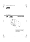
HD NETWORK CAMERA
VN-H37U
VN-H137U
VN-H237U
VN-H237VPU
VN-H57U
VN-H257U
VN-H257VPU
VN-H157WPU
Instructions
(Setting)
LST1244-001C
Getting Started
Contents
Getting Started
Contents ............................................. 2
Camera Setting Requirements
Network .............................................. 4
Images ................................................ 7
Operating protocol .............................. 7
Setting Pages ..................................... 8
Pages Available to Each User .......... 10
Internet Explorer Setting
Settings ............................................. 12
How to Open the Setting Page ...... 12
Basic Setting1 Page ...................... 13
Basic Setting2 Page ...................... 15
Camera Page ................................ 18
Encoding Page .............................. 26
Audio Page .................................... 33
Alarm Page ................................... 35
Alarm Environment Page .............. 40
Storage Page ................................ 42
PTZ Page ...................................... 49
Auto Patrol Page ........................... 50
Privacy Mask Page ....................... 52
Motion Detection Page .................. 54
Audio Detection Page ................... 56
Tampering Detection Pages .......... 58
Network Page ................................ 59
Protocol Page ................................ 61
Register Information ...................... 64
Create Server Certificate Page ..... 65
Multicast Page ............................... 66
Access Restrictions Page ............. 68
Time Page ..................................... 70
Password Page ............................. 72
Focus Page ................................... 74
Maintenance Page ........................ 78
LED State Page ............................ 81
List of Factory Defaults of
Each Page .............................. 82
Miscellaneous Page ...................... 86
Operation Page ............................. 87
Settings Page ................................ 88
Position List Page ......................... 96
Patrol Settings Page ..................... 97
2
Operations
Built-in Viewer Operations ................ 98
Screen Configuration ..................... 99
Picture Quality Setting ................. 101
PTZ Settings ................................ 104
PTZ Control ................................. 106
Unicast Settings ........................... 108
Multicast Settings ........................ 110
On Screen Display Settings ......... 112
Settings related to Audio Monitor ... 118
Other Setting ............................... 120
Exiting the Built-in Viewer ............ 121
Others
Troubleshooting .............................. 122
HTTPS and SNMP Function Update
Procedure ................................. 125
How to read this manual
䡵 Symbols in this manual
Caution
: Operational precautions are
provided.
Note
: Limitations related to functions
and use, and other helpful
information are provided.
A
: Reference pages or reference
items.
䡵 Contents of this manual
● This manual explains the system setup
using Internet Explorer, and the Built-in
Viewer operations.
● Our company holds the copyright of this
manual. This manual may not be reprinted
or reproduced either in part or in whole
without prior consent from the company.
● Windows and Internet Explorer are
registered trademarks of Microsoft
Corporation in the United States and other
countries.
● Product names of other companies
described in this manual are trademarks or
registered trademarks of the respective
companies. Symbols such as 姠, 姞 and 姝
are omitted in this manual.
● Design, specifications and other contents
described in this manual are subject to
change without prior notice for purposes of
improvement.
● The screens and windows shown in this
manual may slightly differ from the actual
ones.
● For the standard camera installation, refer
to "Instructions (Installation)" and the
separate "Safety Precautions" manual.
● The features and settings unique to each
model are identified by the camera model
and series name.
䡵 Copyright
● Please note that broadcasting materials
recorded with this camera for profit or for
the general public to watch may violate the
author's rights protected under copyright
law.
● Use of recorded materials without prior
consent from the author is forbidden under
copyright law except in limited, specific
instances.
3
Camera Setting Requirements
Network
If JPEG file size per piece is 120 KB, the total bit
rate will be:
120 KB x 15 fps = 1800 KB/s
= Approx. 14.4 Mbps
● Ensure that there is sufficient network
bandwidth for the data volume to be sent out
by camera. Also, do not send multicast
stream that exceeds the bandwidth. If the
entire bandwidth is used by the multicast
stream, you may fail to control the camera via
the network.
● Data volume to be sent by camera varies with
the settings and number of distributions.
● The maximum bit rate for transmission is
about 20 Mbps.
For detailed bit rate settings, see the "Encoding"
page. (A Page 26)
If Multi Resolution is selected, the JPEG file size
varies with the channels used.
For example, when 2 fps of 30 KB JPEG file and
3 fps of 10 KB JPEG file are sent, the total frame
rate will be:
30 KB x 2 fps + 10 KB x 3 fps = 90 KB/s
= Approx. 0.72 Mbps
Estimation of Total Bit Rate
The total JPEG bit rate from camera is
determined by the JPEG file size, number of
clients, and number of frames requested by
clients. The total H.264 bit rate from camera is
determined by the number of distributions.
Design the system by considering these points.
Bit Rate of JPEG Stream
The JPEG file size per frame varies with the
encoding settings as well as input video signals.
When AFS (or Average File Size) is selected,
image is encoded so that the average size of
multiple JPEG files becomes the target file size.
If VFS (or Variable File Size) is selected, the
quantization table during JPEG encoding will be
maintained, and the file size will be increased or
decreased according to the input signals.
For JPEG file size details, see the "Encoding"
page. (A Page 26)
The maximum number of distributions varies with
the bit rate settings as well as the client's
requested frame rate. Up to 20 streams can be
distributed (including multicast). The total frame
rate refers to the sum of these frame rates.
For example, when 10 fps is requested by two
clients, and in addition, multicast is transmitted
at a rate of 10 fps, the total frame rate will be:
10+10+10 = 30 fps
For example, when 5 fps is requested by two
clients, and in addition, multicast is transmitted
at a rate of 5 fps, the total frame rate will be:
5 + 5 + 5 = 15 fps
Bit Rate of H.264 and MPEG-4 Streams
You can select either the Variable Bit Rate
(VBR) or Constant Bit Rate (CBR) system for
H.264 and MPEG-4 streams.
When the VBR system is selected, the bit rate
varies according to the condition of input video
signals. The VBR system delivers a stable
picture quality, but it is difficult to forecast the bit
rate.
When the CBR system is selected, data is
encoded at a fixed bit rate regardless of the
condition of input video signals. The picture
quality varies under the CBR system, but the bit
rage can be easily forecasted.
You can specify an estimated bit rate for both
VBR and CBR. (64 kbps to 8192 kbps)
Memo:
● "MPEG-4" is represented on this unit's
screens as "MPEG4".
Audio Data Size (for Audio-Compatible
Models Only)
Up to 2 streams of audio data can be sent. Up to
1 stream of audio data can be received. Each
audio data stream is 64 kbps. The size of audio
data can be calculated via the following formula:
64 kbps x number of streams
The number of streams should be the total of the
number of TCP streams being sent (the number of
clients) plus the number of multicast streams
being sent/received. For example, if the camera is
sending 2 streams of audio and receiving 1
stream of audio, the data size will be the following:
64 kbps x 3 = 192 kbps
4
Restrictions on the Number of
Distributions for Camera
The maximum number of distributions for
camera is determined by the settings as well as
requirements from the client.
For JPEG distribution, you can select either
AFrame Rate PriorityB mode or AClient Number
PriorityB mode. AFrame Rate PriorityB mode
distributes JPEG images according to the frame
rate requested by the client. The maximum
number of distributions is determined based on
the highest bit rate within the distribution
streams. For AClient Number PriorityB mode, if
there are requests from multiple clients, JPEG
images are distributed in a lower frame rate than
that requested to cater to multiple clients. It can
accept 20 distribution requests as the maximum
number of clients.
䡵 When Frame Rate Priority Mode is
Selected
JPEG images are distributed as the frame rate
requested by the client.
When a distribution request that exceeds the
maximum number of distributions is received,
this request is denied.
● When only JPEG images are distributed
For example, if Client A requests for JPEG at
1 Mbps, while Client B requests for JPEG at
5 Mbps, additional 2 stream (total 4 streams) of
distribution are possible for request below 5 Mbps.
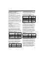
Maximum number of distributions when only
JPEG images are distributed
Distribution at
Maximum
Total
maximum bit rate
number of
maximum
distributions
bit rate
less than 1 Mbps
20
20 Mbps
less than 5 Mbps
4
20 Mbps
less than 10 Mbps
2
20 Mbps
Greater than
Greater than
1
20 Mbps
10 Mbps
● When both JPEG and H.264 data is distributed
When both JPEG and H.264 images are distributed
simultaneously, up to two clients for JPEG and
three clients for H.264 can be distributed,
respectively. However, distribution requests that
exceeds a total bit rate of 20 Mbps will be denied.
Maximum number of distributions when
JPEG and H.264 data is distributed
Maximum
Total maximum
number of
bit rate
distribution
JPEG
2
10 Mbps
H.264
3
10 Mbps
● When distributing only H.264 data
The maximum number of distributions is determined
by the preset bit rate. When a distribution request
that exceeds the maximum number of distributions
is received, this request is denied.
Maximum number of distributions when
H.264 data is only distributed
Maximum bit rate
per distributions
less than 1 Mbps
less than 3 Mbps
less than 6 Mbps
less than 10 Mbps
Greater than
10 Mbps
Maximum
number of
distributions
20
6
3
2
1
Total
maximum
bit rate
20 Mbps
20 Mbps
20 Mbps
20 Mbps
Greater than
20 Mbps
䡵 When Client Number Priority Mode is
Selected
● When only JPEG images are distributed
If the distribution request would be accepted in
the frame rate priority mode, distribution works in
the same way as frame rate priority mode,
where JPEG images are distributed at the frame
rate requested by the client. If the distribution
request would be denied in the frame rate
priority mode, the frame rate is controlled such
that the maximum bit rate is as shown in the
following table, to accept distribution requests
from up to 20 clients. For example, if Clients A
and B request for JPEG at 10 Mbps, the frame
rate will be reduced such that the distribution bit
rate to each client is less than 5 Mbps.
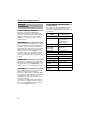
Maximum bit rate when only JPEG data is
distributed
Current number
of distributions
Maximum bit
rate
2 or less
3 to 4
5 to 20
10 Mbps
5 Mbps
1 Mbps
Total
maximum
bit rate
20 Mbps
20 Mbps
20 Mbps
● When both JPEG and H.264 data is distributed
When both JPEG and H.264 images are
distributed, distribution works in the same way as
frame rate priority mode if the distribution request
would be accepted in the frame rate priority
mode. If the distribution request would be denied
in the frame rate priority mode, the frame rate is
controlled such that the maximum bit rate is as
shown in the left table (Maximum number of
distributions when JPEG and H.264 data is
distributed), to accept distribution requests for up
to 20 a total number of 20 JPEG and H.264
distributions. However, distribution requests for
which the total bit rate of the H.264 distribution
stream exceeds 10 Mbps will be denied.
5
Camera Setting Requirements
Network
(continued)
Insufficient Network Bandwidth
When there is insufficient bandwidth, the
number of JPEG frames (frame rate) that the
client can acquire will decrease. Also, the image
distribution will delay. In the case of H.264/
MPEG-4, noise interference may occur and
playback may fail.
List of Protocols and Port Numbers
used by Camera
The camera uses the following protocols and
port numbers. Ensure that these ports are
allowed through the firewall when a firewall is to
be installed.
Protocol/Port
number
Source
TCP/80
JPEG/H.264/MPEG-4
acquisition, Web
Settings page, API,
audio acquisition
TCP/554
RTSP
TCP/10020
TCP/10021
TCP/10023
(Reserved for
adjustment)
TCP/32040
Alarm distribution
TCP/49298
Audio data reception
Network Delay
When the client acquires JPEG via TCP, camera
will send out data while checking the ACK from
the client at the same time. For networks with
considerably delay, data cannot be sent out until
ACK is received, and therefore the frame rate
will drop. In the case of H.264/MPEG-4, noise
interference may occur and playback may fail.
A decrease in the frame rate due to network
delays can be eliminated by receiving data via
multicast.
Network Jitter
When there is considerable network jitter, delay
time may be prolonged and the image frame rate
may drop. In the case of H.264/MPEG-4, noise
interference may occur and playback may fail.
Packet Loss
When acquiring images from camera via TCP,
packet loss may be recovered by TCP
transmission. When there is considerable delay
in the network, however, data may lost and the
image frame rate may drop. In the case of
H.264/MPEG-4, noise interference may occur
and playback may fail.
If a packet is lost during multicast transmission
from camera, the image frame rate may drop. In
the case of H.264/MPEG-4, noise interference
may occur and playback may fail.
6
Purpose of use
Destination
TCP/20, 21
FTP
TCP/25
Mail
TCP/110
POP (Mail delivery)
TCP/User-defined
number
Sending alarm
UDP/123
SNTP
UDP/User-defined
number
Sending alarm
Images
Protocols for discovery of surveillance devices,
acquisition and modification of surveillance
device settings, and audio/video data transfer
are standardized under ONVIF.
The initial user name and password are set as follows:
H.264 Profiles
High profiles can maintain high image quality
with a low bit rate, but as the decoder needs to
support high profiles, the processing load on the
decoder becomes heavier.
Compared to high profiles, baseline profile offers
lower compression performance, but the
processing load on the decoder will be reduced.
Selecting high profiles is recommended if the
decoder has sufficient processing ability.
The camera supports both the H.264 Baseline
Profile and H.264 High Profile standards.
User name: admin
Password: jvc
This camera fulfills the ONVIF test specification
version 1.02.
PTZ (Pan, Tilt, Zoom)
This camera has a digital PTZ function. While
monitoring, the function can cut out an arbitrary area,
move within the range of shooting and enlarge the
image as if you were operating a PTZ camera.
Operating protocol
PSIA
This device conforms with PSIA (Physical
Security Interoperability Alliance) specifications.
PSIA is an organization whose aim is to promote
the interoperability of IP-enabled security devices.
Initial user name and password are set as follows:
User name: psia
Password: jvc
The RTSP of this device complies with
RFC2326. You can set up to 3 encoders. The
RTSP URL for each encoder is as follows:
Encoder No.1
rtsp://192.168.0.2/PSIA/Streaming/channels/0
Encoder No.2
rtsp://192.168.0.2/PSIA/Streaming/channels/1
Encoder No.3
rtsp://192.168.0.2/PSIA/Streaming/channels/2
ONVIF
This camera supports ONVIF (Open Network Video
Interface Forum). ONVIF is a forum that is
standardizing surveillance device network protocols.
7
Camera Setting Requirements
Setting Pages
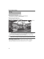
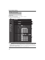
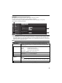
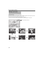
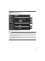
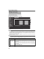
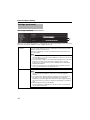
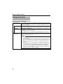
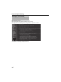
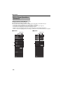
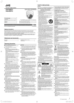
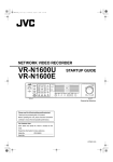
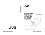
Selection of Languages on Setting Pages
There is a radio button for selecting the language at the right top corner of the setting pages, however
the language will be automatically set according to the OS environment of your computer. If you select
Japanese while using an English-language OS, it may not be correctly displayed because there is no
Japanese environment. Select a language suitable for the OS of your computer on the setting pages.
For how to open the setting pages, see "How to Open the Setting Page". (A Page 12)
Radio button for selecting languages
Memo:
● Your settings are stored in the Cookie folder.
● Once you have set a language, all information is displayed in the selected language after the next
startup.
8
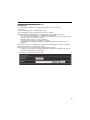
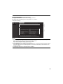
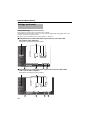
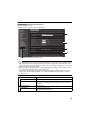
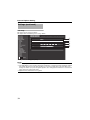
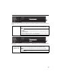
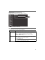
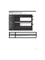
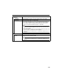
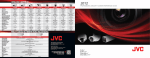
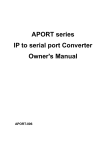
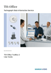
Uploading and downloading of the
Language File
You can change the language on setting pages and built-in viewer of the camera.
● Procedure
(1) Click "Download" button on the Maintenance page.
(2) Save "language.ini" file to the appropriate folder in the computer.
(3) Edit the downloaded "language.ini" file using Notepad or general purpose text editor.
- Current texts are described after "=". Change them to desired text.
- You can write comments after the ";". Comments are annotations for each line and all the text
from the ";" to the end of the line is ignored.
- Maximum number of texts in one line is 126 bytes.
- Save the file after editing. Do not change the file name.
- Western European language (ISO-8859-1) is supported. Double byte character set is not
supported.
(4) Click "Browse" button on the Maintenance page and select "language.ini" file which you edited.
(5) Click "Upload" button on the Maintenance page.
(6) Select "Custom", then click "Apply" button on the Maintenance page.
- Language is replaced after reloading the Maintenance page. When language is not replaced,
please reload the Maintenance page again.
● Following GUI is added to Maintenance page.
9
Camera Setting Requirements
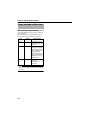
Pages Available to Each User
Enter User Name and Password
User name and password entry will be required
at the beginning.
There are three access authorization levels to
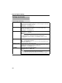
camera. The factory settings are as follows.
User
Name
Default
password
Authorization
levels
admin
jvc
All operations and
setting changes are
allowed.
operator
jvc
The following items
cannot be operated,
and setting changes
are not permitted.
[Basic Setting1]
[Network] [Protocol]
[Access Restrictions]
[Time] [Password]
[Maintenance]
user
jvc
Viewing of images
and some
operations are
permitted.
Memo:
● When accessing to the camera from Internet
Explorer, refer to the "Instructions (IP Address
Settings)."
10
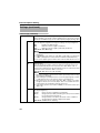
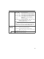
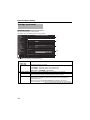
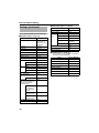
Pages that Users Have Access to
Restrictions are placed on the pages that users
have access to. In addition, links on the setting
pages are also displayed according to the
access privileges of the user.
䢇 operator
Basic Setting2
[Camera]
[Encode]
Details
[Camera]
[Encoding]
[Audio](VN-H57U/H257U/
H257VPU/H157WPU only)
[Alarm]
[Alarm Environment]
[Storage]
[PTZ]
[Auto Patrol]
[Privacy Mask]
[Motion Detection]
[Audio Detection]
(VN-H57U/H257U/
H257VPU/H157WPU only)
[Tampering Detection]
[Multicast]
[Focus](VN-H57U/H257U/
H257VPU/H157WPU only)
[LED Settings]
[Miscellaneous]
[Operation]
[Settings]
[Position List]
[Patrol Settings]
䢇 admin
Basic Setting1
[Network]
[Time]
Basic Setting2
[Camera]
[Encode]
Details
[Camera]
[Encoding]
[Audio](VN-H57U/H257U/
H257VPU/H157WPU only)
[Alarm]
[Alarm Environment]
[Storage]
[PTZ]
[Auto Patrol]
[Privacy Mask]
[Motion Detection]
[Audio Detection]
(VN-H57U/H257U/
H257VPU/H157WPU only)
[Tampering Detection]
[Network]
[Protocol]
[Multicast]
[Access Restriction]
[Time]
[Password]
[Focus](VN-H57U/H257U/
H257VPU/H157WPU only)
[Maintenance]
[LED Settings]
[Miscellaneous]
[Operation]
[Settings]
[Position List]
[Patrol Settings]
䢇 user
Details
[Miscellaneous]
11
Internet Explorer Setting
Settings
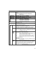
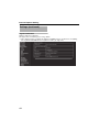
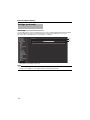
How to Open the Setting Page
1. Enter IP address of camera in the address bar of Internet Explorer.
(for example, the factory default of Ahttp://192.168.0.2B)
2. Enter the user name and password.
(The factory default is AadminB and AjvcB)
3. The Built-in Viewer of the camera is displayed.
Click here.
Memo:
● When IP address entry, see the AInstructions (IP Address Settings).B
● The [Security Information] screen appears before the top page display. Press the [OK] button to
proceed. To suppress this warning screen, correct the Internet Explorer settings as follows.
● Select [Tools] - [Internet Options] - [Security] - [Trusted sites].
● Then, select [Custom Level] and [Miscellaneous] and set [Display mixed content] to AEnableB.
Note:
● Do not reset the camera and do not turn the power supply Off immediately after you have changed
the settings. If done, your settings are lost and the camera may be returned to the factory defaults.
4. Click [Details] of the Built-in Viewer.
● [Basic Setting1] page will be opened if accessed by user name AadminB. (A Page 13)
● [Basic Setting2] page will be opened if accessed by user name AoperatorB. (A Page 15)
● [Miscellaneous] page will be opened if accessed by user name AuserB. (A Page 86)
12
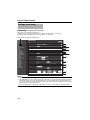
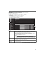
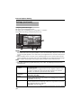
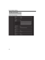
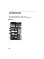
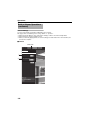
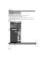
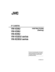
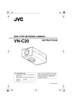
Basic Setting1 Page
This page sets the network basic.
This page can be used during access using AadminB.
Click [Basic Setting1].
A
C
E
G
B
D
F
Memo:
● If you enter the following URL directly into the address bar of Internet Explorer, you can open the
[Basic Setting1] page without going through the Built-in Viewer.
http://192.168.0.2/cgi-bin/display.cgi?basicmenu1.html
● Press the [OK] button to enable the new settings.
● If the [OK] button is pressed upon entering an invalid value, a warning message will appear and the
entry will be denied. Press the [Cancel] button to restore the invalid entry to the value before the
change was made.
13
Internet Explorer Setting
Settings (continued)
Basic Setting1 Page (continued)
Network
A IP Setting
Sets the DHCP client function.
To enable the DHCP, connect the camera to the network environment where
the DHCP server is running.
If you have set IP Setting to DHCP but the DHCP server does not exist, the
camera will start with the IP address of 192.168.0.2 and the subnet mask of
255.255.255.0 approximately 2 minutes after startup.
[Set values: DHCP Disable, DHCP Enable]
B IP Address
Sets the IP address of camera.
[Factory default: 192.168.0.2]
C Subnet
Sets the subnet mask of camera.
[Factory default: 255.255.255.0]
Mask
D Default
Gateway
Sets the default gateway of camera. Enter 0.0.0.0 if you do not want to set a
default gateway.
[Factory default: 0.0.0.0]
Time
E Time (read
only)
Displays the clock time of camera.
The time transmitted by camera is recorded in the JPEG header.
Memo:
● You cannot change the time with this item. For details about the time
settings, see the "Time" page. (A Page 70)
F Time Zone
Sets a time zone.
[Set value: (GMT-12:00) - (GMT) UTC - (GMT+12:45)]
G PC Time to
Click the [Set] button to set the time of computer on the camera.
Camera
Memo:
● Your computer’s time zone cannot be applied. Only the time will be set.
14
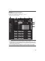
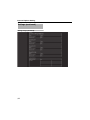
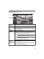
Basic Setting2 Page
This page sets fundamental camera and encoding parameters.
This page can be used during access using AadminB or AoperatorB.
Click [Basic Setting2].
A
B
C
Memo:
● If you enter the following URL directly into the address bar of Internet Explorer, you can open the
[Basic Setting2] page without going through the Built-in Viewer.
http://192.168.0.2/cgi-bin/display.cgi?basicmenu2.html
● Press the [OK] button to enable the new settings.
● If the [OK] button is pressed upon entering an invalid value, a warning message will appear and the
entry will be denied. Press the [Cancel] button to restore the invalid entry to the value before the
change was made.
● "H.264 High" indicates the H.264 High Profile standard.
15
Internet Explorer Setting
Settings (continued)
Basic Setting2 Page (continued)
A Camera ID
Text entered here will be written in the H.264 header and the JPEG comment
segment (item name: camera). It links to the [Camera ID] of the [Camera]
page. (A Page 19)
Memo:
● Refer to the "API Guide" on the file formats of JPEG.
B Scenefile
You can select the setting that is suitable for the shooting scene. You can
select the following eight scenes. You can customize the settings (except
Camera ID) stored in "Scenefile". For details, see the [Camera] page. (A Page
19)
General
: General location
Indoor
: Place with indoor lighting
Outdoor
: For shooting the subject in sunlit conditions
CLVI
: Uses the fog removal function. (A Page 25) This can help
increase visibility in environments where there is a large
difference between lighted and shaded areas, or in environments
where contrast is low due to fog, etc.
Traffic
: For shooting a subject that moves at high speeds, for example,
during road surveillance.
DataSaving: Data can be saved for VBR or VFS coding using noise
suppression. For details, see "Encoding" (A Page 26).
Day (Color): Always shoots in color. This setting is used for shooting in bright
locations such as under in sunlit areas during the day.
Night (B&W): Always shoots in black and white. This setting is used for
shooting in dark locations such as at night or when the object is
illuminated by infrared light.
[Set values: General, Indoor, Outdoor, CLVI, Traffic, DataSaving, Day
(Color), Night (B&W)]
Memo:
● Select "Day (Color) or "Night (B&W)" when you switch the Color or B&W
using an alarm trigger. For details, see the [Alarm] page. (A Page 35)
* The [Set values] in bold letters are factory defaults.
16
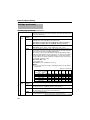
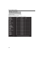
C Encode
Select the frame size for each screen of JPEG and H.264 from the following six
patterns.
䡵 Selectable distribution size
Frame
Size
Frame
Rate
Communication
speed
Bit
rate
I Frame
Interval
1920 x 1080
30 fps
8 Mbps
CBR
30 frames
H.264 High
2 1920x1080 5 fps +
Monitor Output
1920 x 1080
5 fps
2 Mbps
CBR
5 frames
JPEG 1920x1080 +
Monitor Output
1920 x 1080
5 fps
200 KB
AFS
–
4 JPEG 1280x960
1280 x 960
5 fps
120 KB
AFS
–
5 JPEG 640x480
640 x 480
5 fps
30 KB
AFS
–
Set value
1
3
6
H.264 High
1920x1080 30 fps
Set in "Encoding"
Page
Multi-encoding and details can be set on [Encoding]
page.
Memo:
● If [Set in "Encoding" Page] is selected, the details have been set in the [Encode]
of "Encoding" page. (A Page 26)
● Refer to the "API Guide" on the file formats of JPEG.
● The settings of the [PTZ] page (A Page 49) and the [Auto Patrol] page (A Page
50) may not work for some combinations of distribution size in the Encoding
page.
* The [Set values] in bold letters are factory defaults.
17
Internet Explorer Setting
Settings (continued)
Camera Page
This page sets the camera's parameters.
Settings here are linked to the Camera in the "Basic Setting2" page. (A Page 16)
This page can be used during access using AadminB or AoperatorB.
Click [Advanced Settings] and [Camera].
A
B
D
F
G
C
E
H
I
J
K
L
M
N
Memo:
● Press the [OK] button to enable the new settings.
● If the [OK] button is pressed upon entering an invalid value, a warning message will appear and the
entry will be denied. Press the [Cancel] button to restore the invalid entry to the value before the
change was made. If you press the [Cancel] button, other changed items will also be restored to the
values before the change was made.
● Press the [Help] button to display the explanation of functions and settings in a pop-up window.
18
A Camera ID
A character string entered here will be written to the JPEG comment
segment (item name: camera).
Memo:
● You can enter up to 40 characters consisting of alphabets (both upper
case and lower case), numerals, parentheses, commas, periods, spaces
and hyphens. Use the radio button [Japanese / English (Custom)] at the
right top corner of the setting page to select English (Custom).
● All characters entered in the JPEG comment segment will be saved, but
some characters may not be displayed when Camera ID is viewed with
the Built-in Viewer.
● Refer to the "API Guide" on the file formats of JPEG.
B Scenefile
You can select the setting that is suitable for the shooting scene. You can
select the following eight scenes.
You can customize the [Camera] page settings (except Camera ID) stored in
"Scenefile".
General
: General location
Indoor
: Place with indoor lighting
Outdoor
: For shooting the subject in sunlit conditions
CLVI
: Uses the fog removal function. (A Page 25) This can help
increase visibility in environments where there is a large
difference between lighted and shaded areas, or in
environments where contrast is low due to fog, etc.
Traffic
: For shooting a subject that moves at high speeds, for example,
during road surveillance.
DataSaving: Data can be saved for VBR or VFS coding using noise
suppression. For details, see "Encoding" (A Page 26).
Day (Color): Always shoots in color. This setting is used for shooting in bright
locations such as under in sunlit areas during the day.
Night (B&W): Always shoots in black and white. This setting is used for
shooting in dark locations such as at night or when the object is
illuminated by infrared light.
[Set values: General, Indoor, Outdoor, CLVI, Traffic, DataSaving, Day
(Color), Night (B&W)]
Memo:
● Select "Day (Color)" or "Night (B&W)" when you switch the Color or B&W
using an alarm trigger. For details, see the [Alarm] page. (VN-H37U,
VN-H237VPU) (A Page 35)
● If you press the [OK] button, the settings (except Camera ID) of the
[Camera] page will be store in the selected Scenefile.
● Press the [Initialize] button to restore the selected Scenefile to the factory
defaults.
* The [Set values] in bold letters are factory defaults.
19
Internet Explorer Setting
Settings (continued)
Camera Page (continued)
C Brightness
Adjusts the brightness of an image.
Increasing the value brightens dark areas, and decreasing the value makes
bright areas more pleasing to the eye.
[Set values: ⴑ5 to Normal to 5]
D Color Level
Adjusts the color level.
A larger value increases the darkness of color, but a smaller value
decreases the darkness of color.
[Set values: ⴑ5 to Normal to 5]
E Black Level
Adjusts the black level. Setting the value to "Low" darkens the video image.
[Set values: Low, Normal]
Memo:
● If the black level is set to ALowB, this may be too low depending on the
monitoring device, or dark area will become complete black.
● When using the Monitor Output or H.264/MPEG-4 images, set it to
"Normal".
F Gamma
To alter the appearance of dark areas in a video image, adjust the gamma curve.
ON : Perform gamma correction.
OFF : Do not perform gamma correction. The entire image appears dull.
[Set values: ON, OFF]
G Enhance Level
Sets the intensity of edge enhancement.
A larger value increases the intensity of edge enhancement, but a smaller
value decreases the intensity of edge enhancement.
[Set values: ⴑ5 to Normal to 8]
H 3D DNR
The noise on the screen will be reduced.
[Set values: OFF, Low, Mid, High]
Memo:
● With a moving object, the higher the noise reduction (as you select Low Mid - High), the more likely there will be an afterimage.
● You cannot select this when the frame rate is set to 25 fps or higher.
* The [Set values] in bold letters are factory defaults.
20
I White Balance
Adjusts the white balance. White balance can be adjusted for a light source
with a color temperature range of 2300 K to 10000 K.
[Set values: ATW-Wide, ATW-Narrow, AWC]
ATW-Wide
Switches to the Auto-Tracking White Balance (automatic color temperature
tracking) Wide mode. Adjusts the white balance automatically according to
the color temperature of the light. (Color temperature: 2300 K to 10000 K)
ATW-Narrow
Switches to the Auto-Tracking White Balance (automatic color temperature
tracking) Narrow mode. Adjusts the white balance automatically according to
the color temperature of the light. (Color temperature: 3200 K to 8000 K)
AWC
Switches to the Auto-White Balance Control mode. In the AWC mode, values
entered for the [AWC R-Gain] and [AWC B-Gain] items are applied to white balance.
Pressing the [OnePushAWC] button replaces the [AWC R-Gain] and [AWC
B-Gain] values with the values of the AWC execution results.
Memo:
● Execute by filling the screen completely with a white object in a location
with lighting conditions similar to those of the object you are going to shoot.
● Even when white balance is set to "ATW-Wide" or "ATW-Narrow", pressing
the [OnePushAWC] button switches the mode automatically to AWC.
● If you press the [OnePushAWC] button, the changes you made before
pushing the button will be stored and the AWC mode will be executed.
AWC R-Gain
Sets the gain of R (red) when in the AWC mode.
A larger value increases the redness, but a smaller value decreases the redness.
[Set values: 0 to 107 to 255]
AWC B-Gain
Sets the gain of B (blue) when in the AWC mode.
A larger value increases the blueness, but a smaller value decreases the blueness.
[Set values: 0 to 65 to 255]
* The [Set values] in bold letters are factory defaults.
21
Internet Explorer Setting
Settings (continued)
Camera Page (continued)
J ALC
Maintains the video level according to the object brightness. The priority of
motion (by AGC) or the priority of picture quality (by Sense Up) can be selected.
If both are set simultaneously, you can set their priority using the [Priority] option.
AGC
Sets the AGC (automatic gain control) level.
You can adjust the brightness of image according to the object brightness.
OFF
: Disables the AGC function.
Mid
: When the amount of light is insufficient
High
: When the amount of light is particularly insufficient
[Set values: OFF, Mid, High]
Memo:
● If [Easy Day/Night] is set to "Auto", you cannot turn it "OFF". (VN-H137U,
VN-H237U)
● If [Day/Night] is set to "Auto Low", "Auto Mid" or "Auto High", you cannot turn
it "OFF". (This applies to models other than VN-H137U and VN-H237U.)
● The screen appears grainy at dark locations when the AGC function is in use.
Sense
Up
This function is used to raise the sensitivity level by lengthening the
exposure time.
You can specify the number of times by which the sensitivity level is to be
increased automatically when the object becomes dark. When Ax16B is
selected, the sensitivity level will automatically increases continuously until it
is 16 times of the level when AOFFB is selected.
[Set values: OFF, x2, x4, x8, x16, x32, x60]
Memo:
● When the sensitivity is increased, the shutter speed drops and a moving
object appears unnatural.
● Upon raising the sensitivity level, the screen may appear grainy or white,
or white defects may occur. However, this is not a malfunction.
● When Sense Up is set to a value other than AOFFB, flickers occur under
the light of fluorescent or mercury lamps. This is not a malfunction of the
camera, but is due to principles related to Sense Up.
● If the shutter speed is set to 1/50 to 1/10000, you can set the Sense Up to
"OFF" only.
Priority
Sets the priority of ALC (function for maintaining the video level according to
the object brightness).
Combo
: Selects the best combination automatically.
Motion
: Assigns priority to AGC (automatic gain control). This is suitable
for shooting fast-moving objects.
Quality
: Assigns priority to the Sense Up function. This is suitable for
shooting objects requiring a high picture quality.
[Set values: Combo, Motion, Quality]
* The [Set values] in bold letters are factory defaults.
22
K Shutter Speed
Sets the shutter speed.
1/30 to 1/10000
: Fixes the shutter speed.
Auto (1/30 - 1/100)
: Varies the shutter speed automatically between 1/
30 and 1/100 seconds according to the brightness.
Auto (1/30 - 1/1000) : Varies the shutter speed automatically between 1/
30 and 1/1000 seconds according to the brightness.
Auto (1/30 - 1/10000) : Varies the shutter speed automatically between 1/
30 and 1/10000 seconds according to the
brightness.
Flickerless
: Sets a shutter speed to prevent flickering in the
50 Hz power frequency.
[Set values: 1/30, 1/50, 1/60, 1/100, 1/250, 1/500, 1/1000, 1/2000, 1/4000,
1/10000, Auto (1/30-1/100), Auto (1/30-1/1000),
Auto (1/30-1/10000), Flickerless]
Memo:
● AAuto (1/30-1/10000)B is only recommended when using a manual iris
lens.
● Flickers may occur when this is set to a value other than "Flickerless".
● When Sense Up is set to a value other than AOFFB, the shutter speed
cannot be set to a value between 1/250 and 1/10000 seconds.
L Easy Day/Night
(VN-H137U/
H237U only)
Sets the Day and Night mode.
Color
: Keeps color mode activated at all times.
Black & White: Keeps Black & White mode activated at all times.
Auto
: Switches to Black & White mode when the luminance level is
low.
[Set values: Color, Black and White, Auto]
Average: Peak
Exposure detection is set as a ratio of the AVERAGE value to the PEAK value.
[Set values: 10:0, 9:1, 8:2, 7:3, 6:4, 5:5]
* The [Set values] in bold letters are factory defaults.
23
Internet Explorer Setting
Settings (continued)
Camera Page (continued)
L Day/Night
(VN-H37U/H57U/
H257U/H237VPU/
H257VPU/
H157WPU only)
Sets video to Black & White mode. Also allows you to select from among 3
levels for automatically activating Black & White mode in low-light
conditions.
[Set values: Color, Black & White, Auto Low, Auto Mid, Auto High]
If you select AF performance in conjunction with switching modes, AF is
performed when you switch between modes. (VN-H57 only)
Memo:
● The mechanical sound of the infrared filter insertion/removal can be
heard when the mode switches.
● While the mechanical sound can be heard, audio streamed from the
camera is muted. (VN-H257U, VN-H257VPU only)
● If you set "Auto Low", "Auto Mid", or "Auto High", the camera immediately
switches modes when the set amount of illumination is detected.
Color
Color
Average: Peak
Black & White
Black & White
Average: Peak
Keeps color mode activated at all times.
The color mode peak photometry rate is set as a ratio of the AVERAGE
value to the PEAK value.
[Set values: 10:0, 9:1, 8:2, 7:3, 6:4, 5:5]
Keeps Black & White mode activated at all times.
The Black & White mode peak photometry rate is set as a ratio of the
AVERAGE value to the PEAK value.
[Set values: 10:0, 9:1, 8:2, 7:3, 6:4, 5:5]
Auto Low
Switches to Black & White mode when the subject's signal level has a low
level of brightness.
Auto Mid
Switches to Black & White mode when the subject's signal level has a
medium level brightness.
Auto High
Switches to Black & White mode when the subject's signal level has a high
level of brightness.
* The [Set values] in bold letters are factory defaults.
24
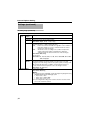
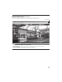
M Back Light
Compensation
Selects the backlight compensation function. Enables unwanted light
sources to be excluded from the photometry area.
OFF
: Disables backlight compensation.
Areas 1 to 4
: Select a photometry area from the four areas.
[Set values: OFF, Area 1, Area 2, Area 3, Area 4]
Photometry area Photometry area Photometry area Photometry area Photometry area
OFF
Area 1
Area 2
Area 3
Area 4
Memo:
● The backlight compensation area is not linked to digital PTZ (Pan, Tilt,
Zoom).
N CLVI
Select the fog removal function.
It is effective in reducing image blur which occurs when zooming in on an
object located at a distance or when shooting in foggy or dusty
environments.
Depending on the shooting conditions, it may be less effective or a noise
may appear in the image, but this is not a camera malfunction.
[Set values: ON, OFF]
Memo:
● CLVI is an abbreviation for Clear Logic Video Intelligence.
* The [Set values] in bold letters are factory defaults.
25
Internet Explorer Setting
Settings (continued)
Encoding Page
This page sets JPEG/H.264/MPEG-4 encoding parameters.
This entry links to the [Encode] item of "Basic Setting2" page. (A Page 17)
This page can be used during access using AadminB or AoperatorB.
Click [Advanced Settings] and [Encoding].
A
B
C
D
Memo:
● Press the [OK] button to enable the new settings.
● If the [OK] button is pressed upon entering an invalid value, a warning message will appear and the
entry will be denied. Press the [Cancel] button to restore the invalid entry to the value before the
change was made. If you press the [Cancel] button, other changed items will also be restored to the
values before the change was made.
● Encoding settings cannot be changed during multicast distribution. (A Page 66)
● If settings on this page are altered during playback using the Built-in Viewer, reboot the viewer.
● There is upper limit to transmission bit rate from the camera. If a bit rate that exceeds upper limit is
specified, this new setting will not be applied. For details on the maximum transmission limit, refer to
the section on "Network". (A Page 4)
● H.264 High indicates High Profile, and H.264 Baseline indicates Baseline Profile.
● The contents displayed in C changes depending on the type of encoding and the item selected.
● If the distribution bit rate exceeds 24 Mbps, the specified frame rate distribution fails.
26
A Encode
Select the encoding from [Single Encode], [Multi Resolution] or [MultiEncode].
C options vary depending on the selected encoding system.
[Set values: Single-Encode, Multi-Resolution, Multi-Encode1,
Multi-Encode2]
Single-Encode
[Set values: JPEG, H.264 Baseline, H.264 High]
Multi-Resolution
[Set values: JPEG, H.264 Baseline, H.264 High]
Multi-Encode1
[Set values: JPEG + H.264 Baseline, JPEG + H.264 High]
Multi-Encode2
[Set values: JPEG(1280x960) + MPEG4(640x480)
JPEG(1280x960) + MPEG4(320x240)
JPEG(640x480) + MPEG4(640x480)
JPEG(320x240) + MPEG4(320x240)]
B Aspect Ratio
Selects the width:height ratio of the image.
[Set values: 16:9, 4:3]
C Single-Encode
Enables Encoder No.1 only out of three channels of encoders. You can
set a frame rate that exceeds 5 fps.
Encoder
No.1
Framesize
Select the frame size of each JPEG or H.264 screen.
Available sizes vary depending on the aspect ratio.
[Set values for aspect ratio 16:9: 1920x1080, 1280x720, 640x360]
[Set values for aspect ratio 4:3: 1280x960, 640x480, 320x240]
Framerate
Select a frame rate.
[Set values: 30 fps (this cannot be set for JPEG if the frame size is 1920
x 1080), 25 fps (JPEG is not supported), 15 fps, 10 fps, 7.5
fps, 5 fps, 3 fps, 2 fps, 1 fps]
Bitrate
(Rate
control
mode)
Select whether to set the control rate mode for single encoding to CBR
(Constant Bit Rate) or VBR (Variable Bit Rate).
CBR
: Data is encoded at a fixed bit rate regardless of the
condition of input video signals. It is easy to estimate the bit
rate. Select from the list of bit rate ranges.
VBR
: The bit rate varies according to the condition of input video
signals. The picture quality is stabled but it is difficult to
estimate the bit rate. Select from the list of bit rate ranges.
[Set values: CBR, VBR]
Bit rate range
[Set values: 64, 128, 256, 384, 512, 768, 1024, 1536, 2048, 3072, 3584,
4096, 8192] kbps
I Frame
Interval
Select the I-frame interval. Encoding starts from the I-frame. Shortening
the interval stabilizes the picture quality even when there area rapid
changes in the video image. However, the picture quality for images with
little change will deteriorate. In addition, when multicast packet loss
occurs, the time interval required to restore the image is shorter.
[Set values: 5, 10, 15, 30, 60, 90, 120] Frame
* The [Set values] in bold letters are factory defaults.
27
Internet Explorer Setting
Settings (continued)
Encoding Page (continued)
C Multi-Resolution
Encoder
No.1
From H.264 High, H.264 Baseline and JPEG, you can select one and set
different frame sizes to up to three channels. The frame rate that can be
set is lower than 5 fps.
Encoding
Display
Displays the encoding system selected in Multi-Resolution.
Framesize
Select the frame size of each JPEG or H.264 screen.
Available sizes vary depending on the aspect ratio.
[Set values for aspect ratio 16:9: 1920x1080, 1280x720, 640x360]
[Set values for aspect ratio 4:3: 1280x960, 640x480, 320x240]
Framerate
Select the frame rate of multi resolution.
[Set values: 15 fps, 10 fps, 7.5 fps, 5 fps, 3 fps, 2 fps, 1 fps]
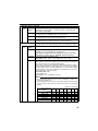
Quality
Select the JPEG picture quality (rate control mode) and picture quality level.
When "AFS" is selected, encoding is performed such that the target file
size is the average size of multiple JPEG images.
When "VFS" is selected, the quantization table during JPEG encoding
will be maintained and the file size will increase or decrease according to
the input signals. When recording JPEG data to a recorder with a limited
storage capacity, note that the maximum recording time may vary as the file
size fluctuates under this setting.
[Set values: AFS, VFS]
Picture quality level
[Set values: Level 1 to Level 3 to Level 7]
Memo:
● You can specify the file size by combining the frame size the picture
quality level.
(Values for reference)
Encoder
No.2
28
Picture quality level
file size (KB)
Frame Size
1
2
3
4
5
6
7
1920 x 1080
1280 x 720
640 x 360
1280 x 960
640 x 480
320 x 240
320
180
80
180
80
27
280
160
60
160
60
20
240
140
40
140
40
13
200
120
30
120
30
10
160
100
25
100
25
8
120
80
20
80
20
7
80
60
15
60
15
5
Encoding
Display
Displays the encoding system selected in Multi-Resolution.
Framesize
Same as for Encoder No.1.
The default value is "1280x720" pixels for Encoder No.2.
Framerate
Same as for Encoder No.1.
The default value is "5 fps" pixels for Encoder No.2.
Quality
Same as for Encoder No.1.
The default values are "AFS" and "Level 3" for Encoder No.2.
* The [Set values] in bold letters are factory defaults.
C Multi-Resolution (continued)
Encoder
No.3
Encoding
Display
When you use Encoder No.3, turn ON the encoding that you selected in multi
resolution. If you select AOFFB, you will not be able to set Encoder No.3.
[Set values: JPEG, OFF]
Framesize
Same as for Encoder No.1.
The default value is "640x360" pixels for Encoder No.3.
Framerate
Same as for Encoder No.1.
The default value is "5 fps" pixels for Encoder No.3.
Quality
Same as for Encoder No.1.
The default values are "AFS" and "Level 3" for Encoder No.3.
C Multi-Encode1
Encoder
No.1
You can specify JPEG for Encode No.1,and H.264 High or H.264
Baseline for No.2. The frame rate that can be set is lower than 15 fps.
Encoding
Display
Displays the AJPEGB encoding system selected in Multi-Encode1.
Framesize
Select the frame size of each JPEG or H.264 screen.
Available sizes vary depending on the aspect ratio.
[Set values for aspect ratio 16:9: 1920x1080, 1280x720, 640x360]
[Set values for aspect ratio 4:3: 1280x960, 640x480, 320x240]
Framerate
Select the frame rate of Multi-Encode1.
[Set values: 15 fps, 10 fps, 7.5 fps, 5 fps, 3 fps, 2 fps, 1 fps]
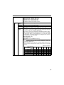
Quality
Select the JPEG picture quality (rate control mode) and picture quality level.
When "AFS" is selected, encoding is performed such that the target file
size is the average size of multiple JPEG images.
When "VFS" is selected, the quantization table during JPEG encoding
will be maintained and the file size will increase or decrease according to
the input signals. When recording JPEG data to a recorder with a limited
storage capacity, note that the maximum recording time may vary as the
file size fluctuates under this setting.
[Set values: AFS, VFS]
Picture quality level
[Set values: Level 1 to Level 3 to Level 7]
Memo:
● The chart below shows file sizes for each combination of frame size
and picture quality level.
● Select between level 1 and level 7. The picture quality increases when
the level value is small. However, the file size increases (see the table
below).
(Values for reference)
Picture quality level
file size (KB)
Frame Size
1
2
3
4
5
6
7
1920 x 1080
1280 x 720
640 x 360
1280 x 960
640 x 480
320 x 240
320
180
80
180
80
27
280
160
60
160
60
20
240
140
40
140
40
13
200
120
30
120
30
10
160
100
25
100
25
8
120
80
20
80
20
7
80
60
15
60
15
5
* The [Set values] in bold letters are factory defaults.
29
Internet Explorer Setting
Settings (continued)
Encoding Page (continued)
C Multi-Encode1 (continued)
Encoder
No.2
Encoding
Display
Displays the encoding system selected in Multi-Encode1.
[For JPEG+H.264 Baseline
: H.264 Baseline]
[For JPEG+H.264 High
: H.264 High]
Framesize
Select the frame size of each JPEG or H.264 screen.
Available sizes vary depending on the aspect ratio.
[Set values for aspect ratio 16:9: 1920x1080, 1280x720, 640x360]
[Set values for aspect ratio 4:3: 1280x960, 640x480, 320x240]
Framerate
Select the frame rate of Multi-Encode1.
[Set values: 15 fps, 10 fps, 7.5 fps, 5 fps, 3 fps, 2 fps, 1 fps]
Bitrate
Select whether to set the control rate mode for full size 30 fps encoding to
CBR (Constant Bit Rate) or VBR (Variable Bit Rate).
CBR : Data is encoded at a fixed bit rate regardless of the condition of
input video signals. It is easy to estimate the bit rate. Select
from the list of bit rate ranges.
VBR : The bit rate varies according to the condition of input video
signals. The picture quality is stabled but it is difficult to
estimate the bit rate. Select from the list of bit rate ranges.
[Set values: CBR, VBR]
Bit rate range
[Set values: 64, 128, 256, 384, 512, 768, 1024, 1536, 2048, 3072, 3584,
4096, 8192] kbps
I Frame
Interval
Select the I-frame interval. Encoding starts from the I-frame. Shortening
the interval stabilizes the picture quality even when there area rapid
changes in the video image. However, the picture quality for images with
little change will deteriorate. In addition, when multicast packet loss
occurs, the time interval required to restore the image is shorter.
[Set values: 5, 10, 15, 30, 60, 90, 120] Frame
* The [Set values] in bold letters are factory defaults.
30
C Multi-Encode2
Encoder
No.1
The following can be set for Encoder No.1 and Encoder No.2.
JPEG(1280 x 960) + MPEG4 (640 x 480)
JPEG(1280 x 960) + MPEG4 (320 x 240)
JPEG(640 x 480) + MPEG4 (640 x 480)
JPEG(320 x 240) + MPEG4 (320 x 240)
The frame rate can be set to 15 fps or lower.
Encoding
Display
Displays the “JPEG” encoding selected for Multi-Encode2.
Framesize
Displays the frame size selected for Multi-Encode2.
Framerate
Specify the frame rate for Multi-Encode2.
[Set values: 15 fps, 10 fps, 7.5 fps, 5 fps, 3 fps, 2 fps, 1 fps]
Picture
Quality
Select the JPEG picture quality (rate control mode) and picture quality level.
When "AFS" is selected, encoding is performed such that the target file
size is the average size of multiple JPEG images.
When "VFS" is selected, the quantization table during JPEG encoding
will be maintained and the file size will increase or decrease according to
the input signals. When recording JPEG data to a recorder with a limited
storage capacity, note that the maximum recording time may vary as the
file size fluctuates under this setting.
[Set values: AFS, VFS]
Picture quality level
[Set values: Level 1 to Level 3 to Level 7]
Memo:
● The chart below shows file sizes for each combination of frame size
and picture quality level.
● Select between level 1 and level 7. The picture quality increases when
the level value is small. However, the file size increases (see the table
below).
(Values for reference)
Picture quality level
file size (KB)
Frame Size
1
2
3
4
5
6
7
1920 x 1080
1280 x 720
640 x 360
1280 x 960
640 x 480
320 x 240
320
180
80
180
80
27
280
160
60
160
60
20
240
140
40
140
40
13
200
120
30
120
30
10
160
100
25
100
25
8
120
80
20
80
20
7
80
60
15
60
15
5
* The [Set values] in bold letters are factory defaults.
31
Internet Explorer Setting
Settings (continued)
Encoding Page (continued)
C Multi-Encode2 (continued)
Encoder
No.2
Encoding
Display
Displays the "MPEG4" encoding selected for Multi-Encode2.
Framesize
Displays the frame size selected for Multi-Encode2.
Framerate
Specify the frame rate for Multi-Encode2.
[Set values: 15 fps, 10 fps, 7.5 fps, 1 fps]
Bitrate
Select whether to set the control rate mode for encoding to CBR
(Constant Bit Rate) or VBR (Variable Bit Rate).
CBR : Data is encoded at a fixed bit rate regardless of the condition of
input video signals. It is easy to estimate the bit rate. Select
from the list of bit rate ranges.
VBR : The bit rate varies according to the condition of input video
signals. The picture quality is stabled but it is difficult to
estimate the bit rate. Select from the list of bit rate ranges.
[Set values: CBR, VBR]
Bit rate range
[Set values: 64, 128, 256, 384, 512, 768, 1024, 1536, 2048, 3072, 3584,
4096, 8192] kbps
I Frame
Interval
Select the I-frame interval. Encoding starts from the I-frame. Shortening
the interval stabilizes the picture quality even when there are rapid
changes in the video image; however, the picture quality for images with
little change will deteriorate. In addition, when multicast packet loss
occurs, the time interval required to restore the image is shorter.
[Set values: 15, 30] Frame
D Monitor Output
Sets monitor output.
[Set values: ON, OFF]
Memo:
● To turn the monitor output ON, set the following in the [Single-Encode]
(JPEG/H.264 Baseline/H.264 High) option:
• Aspect ratio = 16:9
• Frame size = 1920 x 1080
• Frame rate = 5 fps or less
● If you changed the setting of the camera’s monitor selection switch,
you need to restart the camera.
* The [Set values] in bold letters are factory defaults.
32
Audio Page
(These features are not available on VN-H37U/H137U/H237U/H237VPU.)
This page sets audio parameters.
This page can be used during access using AadminB or AoperatorB.
● Click [Advanced Settings] to display the setting menu.
● Click [Audio].
● Press the [OK] button to enable the new settings.
Click [Advanced Settings] and [Audio].
A
B
C
D
䢇 Audio
A Communicate
Sets the audio communication protocol.
When set to Half Duplex, audio sent from the camera to a computer is muted
while audio is being sent from the computer to the camera.
When set to Full Duplex, audio can be sent from a computer to the camera
while audio is also being sent from the camera to the computer.
[Set values: Half Duplex, Full Duplex]
Memo:
● When set to Full Duplex, audio sent from a computer to the camera with an
external microphone attached may return to the computer via the
microphone, resulting in an echo. In this case, use the Half Duplex setting.
B Mike Gain
Sets the gain for an external microphone connected to the camera.
[Set values: 0 dB, 20 dB, 26 dB, 32 dB, AGC]
C Mike Power
Sets the power supply for an external microphone connected to the camera.
[Set values: ON, OFF]
Supply
* The [Set values] in bold letters are factory defaults.
33
Internet Explorer Setting
Settings (continued)
Audio Page (continued)
䢇 Upload
D Audio File
No.1 - No.5
Registers an audio file of the output from the camera's audio output cable or
connector when the alarm is activated.
䡵 To output the registered audio
● Create a file on a computer with the following specifications, and
register it to the camera.
⽧File format WAV file format
⽧Encoding method Linear PCM
⽧Sampling frequency 8 kHz
⽧Quantization bit 16 bit
⽧Monaural
⽧Maximum size 10 seconds (cumulative, for playback files 1 to 5)
● Set [Action] on the Alarm Page to "Play Audio" (A Page 36)
Note:
● If you activate the Speech functions of the Built-in Viewer during audio
file playback, playback of the audio file will stop.
● Playback of an audio file cannot be performed while the Built-in
Viewer's Speech functions are active.
Click the [Browse] button to display the file selection screen, and select the
audio file that you created.
Click the [Upload] button to register the selected audio file to the camera.
Click the [Delete] button to delete the audio file registered to the camera.
Click the [Play] button to play the audio file registered to the camera, and output
it from the camera's audio output cable or connector.
Press the [Stop] button to stop playback of the audio file.
Memo:
● WAV files can be recorded and edited using Sound Recorder in Windows or
other compatible audio processing tool.
34
Alarm Page
This page sets actions to be taken if an alarm occurs.
You can set up to five actions (No. 1 to No. 5).
This page can be used during access using AadminB or AoperatorB.
Click [Advanced Settings] and [Alarm].
A
B
C
D
E
F
G
Memo:
● Press the [OK] button to enable the new settings. Only the items that are valid under the selected
action will be saved. If you set an [Action] to ADisableB, its settings are initialized.
● If the [OK] button is pressed upon entering an invalid value, a warning message will appear and the
entry will be denied. Press the [Cancel] button to restore the invalid entry to the value before the
change was made. If you press the [Cancel] button, other changed items will also be restored to the
values before the change was made.
● The contents displayed changes depending on the selected action and the item of 1st Trigger.
● Press the [Help] button to display the explanation of functions and settings in a pop-up window.
35
Internet Explorer Setting
Settings (continued)
Alarm Page (continued)
A Action
Selects the action performed when the alarm is activated.
Disable
: Performs no action.
Mail
: Sends an email. Specify the recipient's mail address. The mail
subject will be "Alarm from {model name}" (e.g., for VNH257VPU: "Alarm from VN-H257VPU"), and the sender will be
the value for [Camera ID].
Input the message body to be sent in [Mail Text]. Up to 127
alphanumeric characters can be sent. Up to 63 Japanese
characters can be sent.
Set JPEG Attachment to "ON" to attach the latest image to the
mail.
TCP
: Sends the text string input in the [TCP Data] field via TCP to the
recipients specified in [TCP IP Address] and [TCP Port
Number].
UDP
: Sends the text string input in the [UDP Data] field via UDP to
the recipients specified in [UDP IP Address] and [UDP Port
Number].
Position
: Move to the position set at [Action Position Number]
item F (A Page 39).
Play Audio : Plays the audio file registered to the camera.
Refer to [Audio File] on the [Audio] page.
(A Page 34) (VN-H57U/H257U/H257VPU/H157WPU only)
Pin Output1 Make:Changes Pin Output1 to Make.
Pin Output1 Break:Changes Pin Output1 to Break.
Pin Output2 Make:Changes Pin Output2 to Make.
Pin Output2 Break:Changes Pin Output2 to Break.
Pin Output1 Make, Pin Output1 Break, Output2 Make, and
Pin Output2 Break are available on VN-H57U/H257VPU/
H157WPU/H257U only.
Set the time in the [Alarm Output Duration] field.
Switch Scene File:Specifies the scene of filming.
[Set values: Disable, Mail, TCP, UDP, Position, Play Audio, Pin Output1
Make, Pin Output1 Break, Pin Output2 Make, Pin Output2
Break]
* The [Set values] in bold letters are factory defaults.
36
B 1st Trigger
Select the 1st trigger to perform an action.
[Set values: Pin Input1 Make, Pin Input1 Break, Pin Input2 Make, Pin
Input2 Break, Position, Audio Detection1, Audio Detection2
(VN-H57U/H257U/H257VPU/H157WPU only), Motion
Detection, Tampering Detection, Black & White, Day/Night,
Time]
Memo:
● If you set the [2nd Trigger] to "Disable", an action will be performed when
only [1st Trigger] is triggered. (VN-H57U/H257U/H257VPU/H157WPU
only)
● When "Motion Detection" or "Position" is selected for the [1st Trigger]
trigger, [Max. Interval] and [2nd Trigger] cannot be selected. (VN-H57U/
H257U/H257VPU/H157WPU only)
● "Time" can be specified only when the action is "Switch Scene File".
C Max. Interval
(VN-H57U/
H257U/H257VPU/
H157WPU only)
D 2nd Trigger
(VN-H57U/
H257U/H257VPU/
H157WPU only)
E Mail
This is available when both [1st Trigger] and [2nd Trigger] are set.
Specify the maximum interval between each trigger for [1st Trigger] and [2nd
Trigger].
An action will be performed if [2nd Trigger] occurs within the maximum time
interval after [1st Trigger] occurs.
[Set values: 1 - 3600] sec
Select the 2nd trigger to perform an action.
[Set values: Disable, Pin Input1 Make, Pin Input1 Break, Pin Input2 Make,
Pin Input2 Break]
Mail Settings
: If you have set the [SMTP Server], [Port Number], and
[Sender Mail Address] on the [Alarm Environment]
page, the AConfiguredB message is shown. If not set,
the ANot configuredB message is shown. For details
about the mail setup, refer to "Alarm Environment
Page". (A Page 40)
Mail Address
: Enter the recipient's mail address.
Mail Text
: Enter the mail text. You can enter text consisting of up
to 127 alphanumeric characters. Or a text of up to 63
dual-byte characters can be entered.
JPEG Attachment : Specify whether or not to attach an image file to the
mail. To attach JPEG images, check the Attach box and
select the transmission channel.
Encoder
: Specifies an Encoder No. for encoding of attached
JPEG files.
Memo:
● You cannot select [Attach JPEG] if there is no channel with Encode set to
JPEG.
* The [Set values] in bold letters are factory defaults.
37
Internet Explorer Setting
Settings (continued)
Alarm Page (continued)
E TCP
TCP IP Address
: Enter the IP address or FQDN of the destination of TCP
notification.
TCP Port Number : Enter the port number of the destination of TCP
notification. (1 to 65535)
TCP Data
: Enter a character string to be sent for TCP notification.
You can enter text consisting of up to 127 alphanumeric
characters. Or a text of up to 63 dual-byte characters
can be entered.
JPEG Attachment : Specify whether or not to attach an image file. To attach
JPEG images, check the Attach box and select the
transmission channel.
Encoder
: Specifies an Encoder No. for encoding of attached
JPEG files.
Memo:
● You cannot select [Attach JPEG] if there is no channel with Encode set to
JPEG.
E UDP
UDP IP Address
E Switch Scene
Scene File
File
: Enter the IP address or FQDN of the destination of UDP
notification.
UDP Port Number : Enter the port number of the destination of UDP
notification. (1 to 65535)
UDP Data
: Enter a character string to be sent for UDP notification.
You can enter text consisting of up to 127 alphanumeric
characters. Or a text of up to 64 dual-byte characters
can be entered.
: Select the scene file to change.
For details of the scene file, see the [Camera] page. (A Page 19)
[Set values: General, Indoor, Outdoor, CLVI, Traffic, DataSaving, Day
(Color), Night (B&W)]
E Position
Action Position Number:Sets a position number to move.
[Set values: 0 to 19]
E Play Audio
Audio File : For selecting the file number to play when the [Action] item is
set to "Play Audio".
(VN-H57U/
H257U/H257VPU/
H157WPU only)
E Pin Output1 Make,
Pin Output1 Break,
Pin Output2 Make,
Pin Output2 Break
(VN-H57U/H257U/
H257VPU/
H157WPU only)
[Set values: 1 to 5]
Alarm Output Duration: For specifying the output time when the [Action] item
is set to "Pin Output1 Make", "Pin Output1 Break",
"Pin Output2 Make", or "Pin Output2 Break".
[Set values: 0 / 100 to 5000] msec
* The [Set values] in bold letters are factory defaults.
38
F Action Position
Number
For setting the position number to move to when [Action] item A is set to
"Position".
[Set values: 0 to 19]
F Audio File
For selecting the file number to play when [Action] item A is set to "Play
Audio".
[Set values: 1 to 5]
F Trigger Position
For setting the position number to move to when [1st Trigger] item B is set to
"Position".
[Set values: 0 to 19]
Number
F Time
Time : Executes an action at the time you have entered.
[Set values: 00H00M-23H59M]
F Day/Night
Color
(VN-H37U/
H237VPU/H57U/
H257U/H257VPU/
H157WPU only)
: Executes an action when the image changes from Black and White
to color.
Black and White: Executes an action when the image changes from color to
Black and White.
Memo:
● This function is valid only for models with Day and Night.
G Time Filter
Sets the alarm action in each day of week, and sets the corresponding time
of the day.
Applicable day of week: Sunday, Monday, Tuesday, Wednesday, Thursday,
Friday, Saturday
Alarm action
: Unmask All
Mask All
Unmask Span
Mask Span
Applicable time period: Specify the alarm start and end times.
* The [Set values] in bold letters are factory defaults.
39
Internet Explorer Setting
Settings (continued)
Alarm Environment Page
This page sets up the alarm environment.
This page can be used during access using AadminB or AoperatorB.
Click [Advanced Settings] and [Alarm Environment].
A
B
Memo:
● Press the [OK] button to enable the new settings.
● If the [OK] button is pressed upon entering an invalid value, a warning message will appear and the
entry will be denied. Press the [Cancel] button to restore the invalid entry to the value before the
change was made. If you press the [Cancel] button, other changed items will also be restored to the
values before the change was made.
40
A Mail Settings
(VN-H57U/H257U/
H257VPU/H157WPU
only)
SMTP Server
For setting the mail options when [Mail] is selected as the action on the
Alarm page. If an SMTP server, a port number or a sender's mail
address has been set, "Preset" will be displayed.
Sets the IP address or FQDN of the SMTP server.
Memo:
FQDN (Fully Qualified Domain Name)
This refers to a domain name that has been completely specified, without
abbreviation of the host or domain names on a TCP/IP network.
For example, with a host name of www and a domain name of
victor.co.jp, the FQDN representation is "www.victor.co.jp".
Japanese cannot be used in a FQDN. If you have configured an FQDN,
configure a DNS server on the Network Basic page as well. (A Page 59)
Port Number
Enter the port number.
[Set values: 0 - 110 - 65535]
Send Mail Address
Set the sender's mail address.
POP
before
SMTP
To enable [POP before SMTP], select "Enable" and set up the POP server.
POP
Server
Sets the IP address or FQDN of the POP server.
Port
Number
Enter the port number.
[Set values: 0 - 110 - 65535]
User
Name
Enters a user name.
Password
B Alarm output
Enters a password.
Configure settings related to alarm output from an alarm output cable or
connector.
Duration
Sets the output duration for [Manual Output].
[Set values: 0/ 100 - 1000 - 5000] msec
Manual Output
Manually operate alarm output.
The current output status is displayed on the right side. When [Duration]
is set to "0", pressing the [Make] button sets the alarm to make output,
and pressing the [Break] button sets the alarm to break output.
When [Duration] is set to other than "0", pressing the [Make] button sets
the alarm to make output only for the output duration time, and then
changes it to break output.
When [Duration] is set to other than "0", pressing the [Break] button sets
the alarm to break output only for the output duration time, and then
changes it to make output.
* The [Set values] in bold letters are factory defaults.
41
Internet Explorer Setting
Settings (continued)
Storage Page
This page sets up data recording.
This page can be used during access using AadminB or AoperatorB.
Click [Advanced Settings] and [Storage].
A
B
C
D
E
F
G
H
Memo:
● Press the [OK] button to enable the new settings.
● If the [OK] button is pressed upon entering an invalid value, a warning message will appear and the
entry will be denied. Press the [Cancel] button to restore the invalid entry to the value before the
change was made. If you press the [Cancel] button, other changed items will also be restored to the
values before the change was made.
● Displayed options will change, depending on the selected Storage mode.
42
A Storage Mode
Selects a storage mode. Depending on the selected storage
mode, B options vary.
[Set values: OFF, FTP Record]
If A Storage Mode is set to "FTP Record", FTP Record options will be displayed.
B FTP Server
C Path
Sets an IP address of FTP server or FQDN.
Sets a path name. If the [Path] is left blank, the FTP transfer is
made to the home directory of FTP server.
Memo:
● To make an FTP transfer to a directory locating under the
home directory:
Sets the directory name in the [Path] field.
Separate directories by delimiter A/B from each other.
Example: subdir1/subdir2
● If A/B is set at the beginning of directory name, the destination
directory of FTP transfer depends on the FTP server.
D User Name
E Password
Enters a user name.
F FTP Record Mode
Sets an FTP recording mode.
Depending on the selected FTP record mode, G options vary.
Constant : Transfers JPEG images to the FTP server at each
specified time.
Enters a password. When a user name is specified, A******B will
be displayed.
Alarm : Transfers JPEG images around the time when the specified
conditions are met to the FTP server.
Constant+Alarm : Enables both Constant and Alarm.
[Set values: Constant, Alarm, Constant+Alarm]
* The [Set values] in bold letters are factory defaults.
43
Internet Explorer Setting
Settings (continued)
Storage Page (continued)
G Constant
Encoder
Sets the continuous recording.
Selects an Encoder for continuous recording.
Memo:
● You can select an Encoder No. for JPEG file encoding.
Interval
Sets a recording interval by seconds.
[Set values: 1 to 65535] sec
File Naming
You can select any of three (3) formats of recording file names.
If you select AAutoB, a file name is created based on the year,
month, day, hours, minutes, seconds, and a number.
Example: 20111114161032-001-2.jpg
If you select AManual1B, a file name is created based on the UserDefined-String which is added by year, month, day, hours,
minutes and seconds.
Example: Camera1_20111114161032001.jpg
If you select AManual2B, a file name is created based on the UserDefined-String only.
Example: Camera1.jpg
[Set values: Auto, Manual1, Manual2]
Sunday to Saturday
Sets the start and end time of recording for each day of week.
[Set values: Unmask All, Mask All, Unmask Span, Mask Span]
If you have selected ASpecify the time period for invoking the actionB
or ASpecify to stop the actionB, you must set the time period.
[Set values: 00H00M-24H00M]
H Alarm
Encoder
Sets alarm recording.
Sets an encoder for alarm recording and a JPEG frame rate.
[Set values: 5 fps, 3 fps, 2 fps, 1 fps]
Memo:
● You can select an Encoder No. for JPEG.
● The frame rates that can be set vary depending on the
encoding settings.
* The [Set values] in bold letters are factory defaults.
44
H Alarm (continued)
Trigger1, Interval,
Trigger2
For the VN-H137U/H237U
Trigger 1 : Sets a condition to record an alarm.
[Set values: Position, Motion Detection, Tampering Detection, time]
Interval: Unavailable.
Trigger 2 : Unavailable.
For the VN-H37U/H237VPU
Trigger 1 : Sets a condition to record an alarm.
[Set values:Position, Motion Detection, Tampering Detection,
Day/Night, time]
Interval: Unavailable.
Trigger 2 : Unavailable.
For the VN-H57U/H257U/H257VPU/H157WPU
Trigger 1 : Sets a condition to record an alarm.
[Set values: Pin Input1 Make, Pin Input1 Break, Pin Input2
Make, Pin Input2 Break, Position, Audio Detection1,
Audio Detection2, Motion Detection, Tampering
Detection, Day/Night, Time]
Interval: [Set values: 1 to 3600]
Trigger 2 : [Set values: Pin Input 1 Make, Pin Input 1 Break,
Pin Input 2 Make, Pin Input 2 Break]
Position Number
Position Number is displayed if Trigger1 is set to APositionB.
This function executes an action if the trigger is moved to the
position entered.
[Set values: 0 to 19]
Day/Night (VN-H37U and
VN-H237VPU only)
Day/Night is displayed if Trigger1 is set to ADay/NightB.
Color : Executes an action when the image changes from Black
and White to color.
Black and White: Executes an action when the image changes
from color to Black and White.
[Set values: Color, Black and White]
Memo:
● This function is valid only for models with Day and Night.
Time
Time is displayed if Trigger1 is set to ATimeB.
This function executes an action at the time you have entered.
[Set values: 00H00M-24H00M]
Pre-Trigger
Sets a trigger time before FTP recording (a recording time before
alarm input) in seconds.
[Set values: 0 to 5 to 60] sec
Post-Trigger
Sets a trigger time after FTP recording (a recording time after
alarm input) in seconds.
[Set values: 0 to 5 to 60] sec
Sunday to Saturday
Sets the start and end time of recording for each day of week.
[Set values: Unmask All, Mask All, Unmask Span, Mask Span]
If you have selected ASpecify the time period for invoking the actionB
or ASpecify to stop the actionB, you must set the time period.
[Set values: 00H00M-24H00M]
* The [Set values] in bold letters are factory defaults.
45
Internet Explorer Setting
memo
46
memo
47
Internet Explorer Setting
memo
48
PTZ Page
This page sets the movement speed for Auto Return and Preset Position.
This page can be used during access using AadminB or AoperatorB.
● First, set the frame size to 640 x 360 or 640 x 480 in the [Encode] page. (A Page 26)
Click [Advanced Settings] and [PTZ].
A
B
Memo:
● Press the [OK] button to enable the new settings.
● If the [OK] button is pressed upon entering an invalid value, a warning message will appear and the
entry will be denied. Press the [Cancel] button to restore the invalid entry to the value before the
change was made. If you press the [Cancel] button, other changed items will also be restored to the
values before the change was made.
Note:
● You can use the Digital PTZ for frame sizes 640 x 360 and 640 x 480 only. (A Page 17)
A Auto Return
Mode
Restores automatically to the state being specified under [Mode] if the
manually operated camera is not operated for the time period specified by
[Return Time].
Sets an action taken after Auto Return.
Disable
: Disables the auto return.
Home
: Returns to the home position.
Auto Patrol
: Restores the auto patrol action.
[Set values: Disable, Home, Auto Patrol]
Return Time
Test
B Preset Position
Speed
Sets a time before restoring the action by Auto Return.
[Set values: 1, 2, 3, 5, 10, 20, 30, 60] min
Click [Execute] to test the Auto Return action.
Specifies the speed to move to the preset position.
Memo:
● The speed to move the preset position of Auto Patrol is not specified in this
setting as the setting of the speed to move the Auto Patrol page is applied.
Speed
[Set values: Moment, Low, Mid, High]
* The [Set values] in bold letters are factory defaults.
49
Internet Explorer Setting
Settings (continued)
Auto Patrol Page
This page sets the Auto Patrol operation to switch and display multiple position images at preset time
interval. Set this page to view registered positions in order.
This page can be used during access using AadminB or AoperatorB.
● First, set the frame size to 640 x 360 or 640 x 480 in the [Encode] page. (A Page 26)
Whole shooting No.0 (Home)
Position1
No.1
Position2
No.5
Position3
No.2
Position4
No.4
Position5
No.3
No.0 (Home)
No.1 (Position1)
No.2 (Position3)
No.5 (Position2)
No.4 (Position4)
No.3 (Position5)
50
Click [Advanced Settings] and [Auto Patrol].
A B
C
D
E
Memo:
● Register the position in [PTZ Settings] of Built-in Viewer. (A Page 105)
● Press the [OK] button to enable the new settings.
● If the [OK] button is pressed upon entering an invalid value, a warning message will appear and the
entry will be denied. Press the [Cancel] button to restore the invalid entry to the value before the
change was made. If you press the [Cancel] button, other changed items will also be restored to the
values before the change was made.
Note:
● You can use the Digital PTZ for frame sizes 640 x 360 and 640 x 480 only. (A Page 17)
A No.
B Title
C Position
Switches camera images in sequence from No.0 to No.19.
D Stay Time
Sets a time interval to display the image of the respective position. (in seconds)
Select "Skip" for positions that you do not want to display by Auto Patrol.
[Set values: Skip, 10, 20, 30, 45, 60, 120] sec
Shows the title of position.
Sets a sequence of position numbers where the camera moves.
[Set values: 0 to 19]
E Moving Speed Set a movement speed to the target position.
[Set values: Moment, Low, Mid, High]
* The [Set values] in bold letters are factory defaults.
51
Internet Explorer Setting
Settings (continued)
Privacy Mask Page
Privacy Mask is a function that can mask a portion of image.
Rectangular privacy mask areas can be set for the camera. Drag the blue rectangular areas on the
screen to set the privacy mask for them.
This page can be used during access using AadminB or AoperatorB.
䡵 46 horizontal by 34 vertical block (For aspect ratio 4:3 or for 1280 x 960,
640 x 480, or 320 x 240 pixels)
Click [Advanced Settings] and [Privacy Mask].
䡵 60 horizontal by 34 vertical block (For aspect ratio 16:9 or for 1920 x 1080,
1280 x 720, or 640 x 360 pixels)
Click [Advanced Settings] and [Privacy Mask].
52
Memo:
● Press the [OK] button to enable the new settings.
● When camera images are acquired by the Built-in Viewer or another client and if this acquisition
exceeds the distribution capability of camera, the video images may not appear on the Privacy Mask
page. When you use the Privacy Mask page, turn the Built-in Viewer and another client Off.
● If the [OK] button is pressed upon entering an invalid value, a warning message will appear and the
entry will be denied. Press the [Cancel] button to restore the invalid entry to the value before the
change was made. If you press the [Cancel] button, other changed items will also be restored to the
values before the change was made.
● The privacy mask that you set also works for the monitor output.
Note:
● Masks cannot be set in a zoomed screen.
● When you open the Privacy Mask settings page, it is displayed in the fixed (full-screen) size. The
size of the mask you have set changes when you zoom.
A Mask
The screen is divided into 46 (horizontal) by 34 (vertical) blocks (for aspect
ratio 4:3) or into 60 (horizontal) by 34 (vertical) blocks (for aspect ratio
16:9). You can specify the positions to be masked in each block.
B Privacy Mask
Turns the Privacy Mask function ON or OFF.
[Set values: ON, OFF]
C Brightness
Sets a brightness of Privacy Mask areas.
When a large value is set, the brightness level increases (becomes white).
When a small value is set, the brightness level decreases (becomes dark).
This setting is common to all blocks.
[Set values: 0 to 4 to 8]
D All Mask
Enables all the privacy masks. Press the [OK] button to enable this setting.
E Clear Mask
Releases all the privacy masks.
* The [Set values] in bold letters are factory defaults.
53
Internet Explorer Setting
Settings (continued)
Motion Detection Page
This page sets the motion detection.
This page can be used during access using AadminB or AoperatorB.
䡵 13 horizontal by 9 vertical block (For aspect ratio 4:3)
Click [Advanced Settings] and [Motion Detection].
䡵 15 horizontal by 9 vertical block (For aspect ratio 16:9)
Click [Advanced Settings] and [Motion Detection].
54
Memo:
● If the [OK] button is pressed upon entering an invalid value, a warning message will appear and the
entry will be denied. Press the [Cancel] button to restore the invalid entry to the value before the
change was made. If you press the [Cancel] button, other changed items will also be restored to the
values before the change was made.
● When camera images are acquired by the Built-in Viewer or another client and if this acquisition
exceeds the distribution capability of camera, the video images may not appear on the Motion Detection
page. When you use the Motion Detection page, turn the Built-in Viewer and another client Off.
● The area valid for motion detection is displayed in blue.
● When motion is detected, the area around the screen is highlighted in red.
A Motion Detection
Area
B Motion Detection
The display screen showing the motion detection area is divided into 13
(horizontal) by 9 (vertical) blocks (for aspect ratio 4:3) or into 15 (horizontal)
by 9 (vertical) blocks (for aspect ratio 16:9). You can specify whether to
enable motion detection in each block.
When you click a block for motion detection. the block turns blue and it
becomes a target of detection. When you click the right-hand mouse button
on the blue block, the blue display is cancelled and detection will not be
applied to this block. If you move the mouse while pressing the right- or lefthand button, you can set up multiple blocks at once.
When you set all blocks and press the [OK] button, the motion detection is
made valid for each block.
Turns the motion detection ON or OFF.
[Set values: ON, OFF]
Memo:
● You cannot set this to [ON] when the frame rate is set to 25 fps.
C Level
Sets a sensitivity of motion detection.
Increasing the number raises the detection sensitivity level and the
detection becomes more sensitive.
[Set values: 0 to 4 to 10]
D All Mask
Deactivates detection regions.
E Clear Mask
Performs motion detection on all blocks.
* The [Set values] in bold letters are factory defaults.
Memo:
● The area display position servers as a reference. Always check its operation.
● A single screen is divided into 135 blocks (13 horizontal by 9 vertical blocks) (for aspect ratio 4:3) or
into 108 blocks (12 horizontal by 9 vertical blocks) (for aspect ratio 16:9). Set the angle of view so
that the size of object for motion detection is larger than the size of multiple blocks.
● Masks cannot be set in a zoomed screen.
● When you open the setting page for motion detection, it is displayed in the fixed (full-screen) size.
Note:
● Flickers of fluorescent lamps may cause motion detection.
● A brightness change due to the light source may be detected as motion.
● The motion detection function is not intended to prevent theft or fire. Also, this function may not
function properly under certain conditions of object and settings.
Our company is not liable for any accident or damage that occurs.
● When [Tampering Detection] or [Audio Detection] is set to AONB, the motion detection function
cannot be used.
55
Internet Explorer Setting
Settings (continued)
Audio Detection Page
(VN-H57U/H257U/H257VPU/H157WPU only)
This page sets the audio detection.
This page can be used during access using "admin" or "operator".
Peak
meter
A
B
C
Click [Advanced Settings] and [Audio Detection].
Memo:
● The meter turns green when below the detection level threshold, and turns red when above the
detection level threshold.
● Press the [OK] button to enable the new settings. settings (except for the selection for A)
● If the [OK] button is pressed upon entering an invalid value, a warning message will appear and the entry
will be denied. Press the [Cancel] button to restore the invalid entry to its previous value. When you press
the [Cancel] button, other entries that you changed will also be restored to their previous values.
● After audio has been detected, if the audio level is below the detection level threshold for 5 seconds
or more, the camera returns to non-detection status.
Note:
● If the audio driver is not installed on your computer, audio detection does not function.
● When [Tampering Detection] or [Motion Detection] is set to AONB, the audio detection function
cannot be used.
56
A No.1, (No.2)
Select the item to use with the peak meter for detection confirmation.
[Set values: No.1, No.2]
B No.1
Audio Detection
Enables/disables detection of No.1.
[Set values: ON, OFF]
Level
Sets the detection level.
[Set values: 0 to 4 to 10]
Detection Time
Detects audio that continues longer than the set time.
[Set values: 0 to 1000 to 3000] msec
C No.2
Sets No.2. This is the same as No.1.
* The [Set values] in bold letters are factory defaults.
57
Internet Explorer Setting
Settings (continued)
Tampering Detection Pages
This page sets the tampering detection.
This page can be used during access using "admin" or "operator".
Click [Advanced Settings] and [Tampering Detection].
Memo:
● If the [OK] button is pressed upon entering an invalid value, a warning message will appear and the
entry will be denied. Press the [Cancel] button to restore the invalid entry to its previous value. When
you press the [Cancel] button, other entries that you changed will also be restored to their previous
values.
● When the Built-in Viewer or another client is acquiring images from the camera and the camera's
transfer capabilities are exceeded, video may not be displayed on the [Tampering Detection] page.
When using the [Tampering Detection] page, disable the Built-in Viewer and other clients.
Note:
● Detection may not be possible due to the installation conditions of the camera or the subject being shot.
● When [Motion Detection] or [Audio Detection] is set to AONB, the tampering detection function
cannot be used.
A Inspection
screen
B Tampering
Detection
When tampering is detected, the area around the viewer becomes
accentuated in red.
Tampering detection is triggered when the video brightness data becomes
focused on a single value. This may take place when the lens has been
blocked, or an obstacle is placed in front of the camera.
Turns tampering detection ON or OFF.
[Set values: ON, OFF]
C Level
Sets the tampering detection level.
Larger numbers will increase the detection level, making it more sensitive.
[Set values: 0 to 4 to 10]
D Detection Time
Sets the minimum time for detecting tampering.
If video determined to be tampering continues for longer than the specified
time, tampering detection is triggered.
[Set values: 5 to 50 to 100] sec
* The [Set values] in bold letters are factory defaults.
58
Network Page
This page sets the network settings.
This page can be used during access using AadminB.
B
D
F
H
K
M
A
C
E
G
I
J
L
N
Click [Advanced Settings] and [Network].
Memo:
● Press the [OK] button to enable the new settings.
● If you change the settings, the camera will restart. The camera takes about 90 seconds to restart.
● If the [OK] button is pressed upon entering an invalid value, a warning message will appear and the
entry will be denied. Press the [Cancel] button to restore the invalid entry to the value before the
change was made. If you press the [Cancel] button, other changed items will also be restored to the
values before the change was made.
● If you change the settings other than host name and DNS server on the [Network] page, all of the
currently operating services are terminated. For example, if you change a setting on the [Network]
page during JPEG, H.264 or MPEG-4 file distribution, the file distributions are stopped and the TCP
connection is disconnected.
59
Internet Explorer Setting
Settings (continued)
Network Page (continued)
IP Setting
A IP Setting
Sets the DHCP client function.
To enable the DHCP, connect the camera to the network
environment where the DHCP server is running.
If you have AenabledB the DHCP but the DHCP server does not exist,
the camera will start with the IP address of 192.168.0.2 and the subnet
mask of 255.255.255.0 approximately 2 minutes after startup. For the
IP address details, see the "Instructions (IP Address Settings)."
[Set values: DHCP Disable, DHCP Enable]
B IP Address
Sets the IP address of camera.
[Factory default: 192.168.0.2]
C Subnet Mask
Sets the subnet mask of camera.
[Factory default: 255.255.255.0]
D Default Gateway
Sets the default gateway of camera.
Enter "0.0.0.0" if you do not want to set a default gateway.
[Factory default: 0.0.0.0]
E Host Name
Sets a host name of camera.
It can consist of alphanumeric characters, hyphen (-), and period (.).
Underscore (_) character is not allowed to use.
F DNS Server
Sets an address of DNS server.
[Factory default: 0.0.0.0]
G MAC Address
H IP Protocol
I IPv6 Address
The MAC address of camera is shown as a hexadecimal number.
Turns the IP Version 6 setting On or Off. (IP Version 4 is usually set to On.)
When you enable the IP Version 6 setting, two address types are
displayed. They are: Alink localB and AglobalB. However, if the IPv6 is
not supported by the connected network, the AglobalB address bar is
shown as ADisabledB.
Other
J Negotiation
Sets the network negotiation.
If you have selected a value other than AAutoB, do not set the connected
network device to AAutoB. Be sure to set it to the same value as the camera.
[Set values: Auto, 100M Full, 100M Half, 10M Full, 10M Half]
Memo:
● The camera and another connecting device on the network may
connect automatically when the other than "Auto" is selected for
the camera and "Auto" is set for the other connecting device.
K TOS(DS field)
Sets a TOS value of IP packets which contain visual data.
[Set values: 0 to 252]
L TTL(unicast)
Sets a TTL value of TCP packets which contain visual data.
[Set values: 1 to 64 to 255]
M TTL(multicast)
Sets a TTL value of UDP packets which contain visual data.
[Set values: 1 to 32 to 255]
N MTU
Sets the maximum size of packets which contain visual data.
[Set values: 1280 to 1500]
* The [Set values] in bold letters are factory defaults.
60
Protocol Page
This page sets the protocol.
This page can be used during access using AadminB.
A
B
C
D
Click [Advanced Settings] and [Protocol].
Memo:
● Press the [OK] button to enable the new settings.
● If the [OK] button is pressed upon entering an invalid value, a warning message will appear and the
entry will be denied. Press the [Cancel] button to restore the invalid entry to the value before the
change was made. If you press the [Cancel] button, other changed items will also be restored to the
values before the change was made.
● When you connect via Internet Explorer after changing protocol settings, enter the address using
the new server port and port number in the address bar.
● The camera's default settings do not support using the HTTPS and SNMP functions. For protocol
settings when using HTTPS with SNMP, see "HTTPS and SNMP Function Update Procedure".
(A Page 125)
A Server Certificate
Specifies settings related to server certificates.
Register Information
Displays valid server certificates.
Local Certification
When you press the [Create Server Certificate] button, displays
the screen for entering information required to create a server
certificate.
B Protocol Settings
HTTP/HTTPS
Sets protocols.
Select the protocol to use.
[Set values: HTTP, HTTPS]
* The [Set values] in bold letters are factory defaults.
61
Internet Explorer Setting
Settings (continued)
Protocol Page (continued)
B Protocol Settings (continued)
HTTP Server Port
You can change the port number for the built-in HTTP server of
the camera.
[Set values: 1 to 80 to 65535]
Memo:
● To access the camera from Internet Explorer, enter the
following in the Internet Explorer address bar when the camera
is set to its default settings.
http://192.168.0.2
If the port number has been changed to 8080, enter it after the
IP address as follows.
http://192.168.0.2:8080
Enter [:] and the port number
● If you change the HTTP server port, the port for the video
stream deliver request also changes.
HTTPS Server Port
You can change the port number for the built-in HTTPS server of
the camera.
[Set values: 1 to 443 to 65535]
Memo:
● To access the camera from Internet Explorer, enter the
following in the Internet Explorer address bar when the camera
is set to its default settings.
https://192.168.0.2
If the port number has been changed to 8080, enter it after the
IP address as follows.
https://192.168.0.2:8080
Enter [:] and the port number
● If you change the HTTPS server port, the port for the video
stream deliver request also changes.
SNMP
Sets SNMP.
[Set values: ON, OFF]
AMX Device Discovery
Protocol
You can change the AMX device discovery protocol. Set this to
"ON" when using the camera with an AMX system.
[Set values: ON, OFF]
* The [Set values] in bold letters are factory defaults.
62
C Standard Surveillance
Sets standard surveillance protocols.
Protocol
PSIA/ONVIF
D JPEG Streaming
Priority
You can change the standard surveillance protocols.
[Set values: PSIA, ONVIF, OFF]
Selects the JPEG image streaming priority.
Selects whether to give priority to the client number for JPEG
image streaming or the frame rate.
Client Number : Gives priority to the streaming client number.
Lowers the JPEG frame rate as delivery
requests increase, allowing delivery to a
maximum of 20 clients.
Framerate
: Gives priority to the frame rate.
Set this to maintain the frame rate for JPEG
images requested by clients. Delivery requests
that exceed the maximum number will be
denied.
[Set values: Client Number, Framerate]
* The [Set values] in bold letters are factory defaults.
63
Internet Explorer Setting
Settings (continued)
Register Information
Displays valid server certificates.
This page can be used during access using AadminB.
● This is displayed when you update the HTTPS and SNMP functions. For directions on updating,
refer to [HTTPS and SNMP Function Update Procedure]. (A Page 125)
64
Create Server Certificate Page
This page is for creating a new server certificate for local certification.
This page can be used during access using "admin".
● This is displayed when you update the HTTPS and SNMP functions. For directions on updating,
refer to [HTTPS and SNMP Function Update Procedure]. (A Page 125)
A
B
C
D
E
F
G
A Country Code
Enter the country code of the local certificate authority.
Use the 2-letter alphabetical country code defined in ISO3166-1 alpha 2.
B State
Enter the state of the local certificate authority.
C City
Enter the city of the local certificate authority.
D Organization
Enter the organization name of the local certificate authority.
E Organization unit
Enter the organization unit name of the local certificate authority.
F Common name
Enter the administrator name or server host name of the local certificate
authority.
G Mail Address
Enter the administrator's mail address.
● Characters that can be input vary by item.
A
A-Z
B ~ E a-zA-Z0-9_ .,+/()F
a-zA-Z0-9 .G
a-zA-Z0-9_@.+"#$-
65
Internet Explorer Setting
Settings (continued)
Multicast Page
(Audio-related functions are only available on the VN-H57U/H257U/H257VPU/H157WPU.)
This page specifies manual multicast streaming.
This page can be used during access using AadminB or AoperatorB.
A
B
C
D
F
E
G
I
H
Click [Advanced Settings] and [Multicast].
Memo:
● To save the changes made to the entire page, press the [OK] button.
● If the [OK] button is pressed upon entering an invalid value, a warning message will appear and the
entry will be denied. Press the [Cancel] button to restore the invalid entry to the value before the
change was made. If you press the [Cancel] button, other changed items will also be restored to the
values before the change was made.
66
Encoder No.1 to No.3
Sets the manual streaming of Encoder No.1 to Encoder No.3.
A Encoding
Displays the AEncodeB being set for each encoder.(A Page 27)
[Display values: JPEG, H.264 Baseline, H.264 High, MPEG4)]
B FrameSize
Displays the "FrameSize" being set for each encoder. (A Page 26)
C FrameRate
Displays the AFrameRateB being set for each encoder. (A Page 26)
You can change it if the encoding is AJPEGB.
[Set values: 30 fps to 5 fps to 1/30 fps]
Memo:
● You can change the frame rate if it is below the limit specified on the
[Basic Setting2] page or on the [Encode] page.
D Destination
Address
E Destination
Port
F Start
Sets a destination address for encoded data streaming.
Set a multicast address. If you have another device for multicast streaming,
set a different multicast address.
[Factory default: Encoder No.1: 225.0.1.1, Encoder No.2: 225.0.2.1,
Encoder No.3: 225.0.4.1]
Sets a destination port number for encoded data streaming. Enter an even
number to meet the RTP. If you have another device for multicast streaming,
you should set a different port number.
If a port number is duplicated, you cannot receive multiple number of
multicast data using a single computer.
[Factory default: Encoder No.1: 49152, Encoder No.2: 59152,
Encoder No.3: 29152]
Saves the encoder settings, and starts manual streaming. The [Stop] button
is displayed during manual streaming.
You cannot change the frame rate, destination address, and destination port
during data distribution.
Memo:
● To save the settings made to the entire page, press the [OK] button.
Audio (VN-H57U/H257U/H257VPU/H157WPU only)
G Destination
Address
H Destination
Port
I Start
Specifies the destination address for audio streaming.
Specify a multicast address. When used with other multicast transmitting
devices, set a separate multicast address for each device.
[Factory default: 225.0.3.1]
Specifies the destination port number for audio streaming.
Specify an even number in accordance with RTP.
When used with other multicast transmitting devices, it is recommended that
you set a separate port number for each device.
If the same port numbers are used, multiple multicasts will not be receivable
on a single computer.
[Factory default: 39152]
For starting and stopping manual distribution.
* The [Set values] in bold letters are factory defaults.
Memo:
● If the camera power supply is turned Off during multicast streaming, the camera will restart multicast
streaming automatically after the camera is restarted.
● Settings A~I are not displayed when the encoder is set to "OFF".
67
Internet Explorer Setting
Settings (continued)
Access Restrictions Page
This page sets the client restrictions.
This page can be used during access using AadminB.
A
B
Click [Advanced Settings] and [Access Restrictions].
Memo:
● Press the [OK] button to enable the new settings.
● If the [OK] button is pressed upon entering an invalid value, a warning message will appear and the
entry will be denied. Press the [Cancel] button to restore the invalid entry to the value before the
change was made. If you press the [Cancel] button, other changed items will also be restored to the
values before the change was made.
● This function applies to H.264, JPEG or MPEG-4. This function does not restrict the access via the
Web browser and the use of API.
Note:
● The Access Restriction function determines the restrictions when TCP connection is made by the
client. If the TCP connection is already established to the client, this TCP connection is not released
even when you sets the access restrictions after the connection.
Client Address
A Address
Restriction
B IP Address
68
You can restrict a client to allow access to the camera using its IP address.
If "Deny" is selected, retrieving H.264, JPEG or MPEG-4 by the IP address
set in [IP Address] option will be denied. An access to the Settings page is
not restricted.
If "Allow" is selected, retrieving H.264, JPEG or MPEG-4 by the IP address
set in [IP Address] option will be permitted. An access to the Settings page is
not restricted.
[Set values: Deny, Allow]
Up to 10 blocked or permitted client IP addresses can be registered.
Note:
● If "Allow" is selected, but all IP address fields are left blank, retrieving H.264, JPEG or MPEG-4 by
all IP addresses will be denied.
An access to the Settings page is not restricted.
Additionally, the camera also denies transmission to an IP address if it is specified via API.
Memo:
● When you set a specific IP address range, enter a combination of IP address and subnet mask in
the [IP Address] field.
● Define the subnet mask using a length between 8 and 30 bits.
For example, when you set the IP address range between "192.168.0.0" and "192.168.0.255", enter
"192.168.0.0/24" (IP-address/Subnet-mask-bit-length).
69
Internet Explorer Setting
Settings (continued)
Time Page
This page sets the current clock time.
This page can be used during access using AadminB.
A
B
C
D
E
F
Click [Advanced Settings] and [Time].
Memo:
● Press the [OK] button to enable the new settings.
● If the [OK] button is pressed upon entering an invalid value, a warning message will appear and the
entry will be denied. Press the [Cancel] button to restore the invalid entry to the value before the
change was made. If you press the [Cancel] button, other changed items will also be restored to the
values before the change was made.
● Adjust the time and the time zone together.
70
A SNTP
Sets the SNTP client function.
OFF :Does not access to NTP server.
ON :Gets the time by periodical accessing to the specified NTP server.
[Set values: OFF, ON]
Memo:
● The time is recorded in the JPEG header when distributed by the camera.
The time recorded in the JPEG header may not continue immediately
before and after the acquisition of time from NTP server.
B SNTP Server
Sets an IP address of NTP server.
[Factory default: 0.0.0.0]
C Interval
Sets a unit and values of measurement for the time interval at which to
access the NTP server.
[Set values: Min (1 - 60), Hour (1 - 24), Day (1 - 31)]
D Time
Displays the clock time of camera.
You can correct the time by entering a value (without seconds).
Memo:
● The time is recorded in the JPEG header when distributed by the camera.
Discontinuity may occur in the JPEG header's time immediately before
and after changing the time.
E Time Zone
Sets a time zone.
[Set value: (GMT-12:00) to (GMT)UTC to (GMT+12:45)]
F PC Time to Camera Click [Set] to set the computer's time on the camera.
* The [Set values] in bold letters are factory defaults.
71
Internet Explorer Setting
Settings (continued)
Password Page
This page sets a password.
This page can be used during access using AadminB.
A
B
C
D
Click [Advanced Settings] and [Password].
A User Name
You must set passwords for the "admin", "operator" and "user".
Memo:
● You can set up to four users each for "admin", "operator" and "user".
● You cannot specify a user name other than the character strings
displayed.
B Password
Enters a password.
A password can be one to 16 alphanumeric characters. Password characters
are case-sensitive.
C Password
Enter the new password again for confirmation.
Re-Input
72
D Action
Enables password settings or deletes them. When you press a button, its
confirmation screen appears.
Set
: Sets the password you have entered.
Delete : Deletes the default password.
Memo:
● Remember that you cannot delete the "admin", "operator", and "user"
factory default passwords.
Note:
● Always handle the password carefully so that you do not forget it.
● If you have forgotten the password, please consult your nearest JVC dealer.
73
Internet Explorer Setting
Settings (continued)
Focus Page
You can adjust the focus from a computer (electric focus) for VN-H57U/H257U/H257VPU/H157WPU.
Select the adjustment mode from the pull-down menu and perform adjustment as necessary.
This page can be used during access using "admin" or "operator".
A
B
Click [Advanced Settings] and [Focus].
Note:
● Before making adjustments via the Focus page, roughly adjust the camera's lens. If the rough focus
is widely out of alignment, focus adjustment may be performed incorrectly.
74
A Focus Status
Focus adjustment operation status.
Ready : Preparing to move.
Stop : Not moving.
Moving : Currently moving.
Error : A moving error occurred.
B Adjust Mode
Sets the adjustment mode.
When using an adjustment mode other than "Select" and you do not perform
any operation for 3 minutes or more, the mode automatically returns to
"Select".
Select : This is the default mode.
Day Focus Adjust : Provides a finer level of adjustment than can be
achieved by performing rough focus adjustment of the
camera lens.
Night Focus Offset : You can mitigate the amount of focus blurring (bokeh)
from infrared exposure.
Back Focus Position Initialize : Perform initialization if you have changed
the lens or if you want to readjust this
camera's lens focus after performing Day
Focus Adjust. (VN-H57U only)
[Set values: Select, Day Focus Adjust, Night Focus Offset, Back Focus
Position Initialize]
Note:
● When adjusting the focus, turn off slow shutter and alarm.
● Do not perform focus adjustment from multiple users.
● If the focus does not move, check if the camera lens's focus adjustment
gear has returned to its original position. (VN-H257U/H257VPU/H157WPU)
● When the electric focus is being used, the motor emits noise.
● When using the electric focus, the field angle may slightly shift. This is not
a malfunction.
● If you select "Day Focus Adjust", "Night Focus Adjust", or "Back Focus
Position Initialize", the camera enters Focus Assist mode and the lens iris
opens. The status LED color also alternates between green and orange.
Focus Assist mode is not automatically disabled after you finish adjusting
the focus. The LED turns green when you select "Select", and the camera
exits Focus Assist mode.
* The [Set values] in bold letters are factory defaults.
75
Internet Explorer Setting
Settings (continued)
Focus Page (continued)
C
D
When you select "Day Focus Adjust" in [B Adjust Mode], the camera automatically enters color mode
and Focus Assist mode. Adjust the focus in a bright environment.
C One Push Auto
Focus
Click the [Execute] button to automatically adjust the focus. This may take
several seconds. When the process is finished, the status becomes "Stop".
Use the viewer to check the focus.
If an error is displayed, check the shooting environment, and execute the
procedure again.
Note:
● Depending on the shooting environment (low contrast, low illumination, a
moving subject, etc.), an error may be displayed, or the focus may not be
set to the optimal position.
● If you perform shooting of a close subject by zooming the lens to the wide
position or shooting of a far subject by zooming the lens to the tele
position, the focus may not be set to the optimal position. (VN-H257U/
H257VPU/H157WPU)
● If the focus cannot be set to the optimal position using One Push Auto
Focus, perform adjustments using manual focus.
D Manual Focus
Moves the focus amount according to the value for each button.
Note:
● If you exceed the range of movement for the focus, nothing happens
even if you push these buttons. In this case, move in the opposite
direction.
● If you move in the opposite direction and there is no point at which you
can achieve focus, perform back focus initialization. Perform fine
adjustment of the focus again with manual focus after roughly adjusting
the camera's lens focus (refer to "Instructions (Installation)"). (VN-H57U
only)
● When using the zoom lens with VN-H57
Perform manual focus adjustment so that the zoom is focused for both
the tele and wide positions.
76
E
When you select "Night Focus Offset" in [B Adjust Mode], the camera automatically enters Black
&White mode and Focus Assist mode. Adjust the offset value in a B&W mode environment to achieve
focus.
E Offset
When using this function and the offset is set to other than "0", the focus is
automatically moved by the offset amount when you enter B&W mode.
Note:
● Before performing Night Focus Offset, make sure to perform Day Focus
Adjust.
● Depending on the shooting environment, the focus may not be set to the
optimal position.
● When the night focus offset is set to other than "0", the motor emits noise
when you switch between color and black/white.
F
When you select "Back Focus Position Initialize" in [B Adjust Mode], the camera automatically enters
color mode.
F Back Focus
Position Initialize
(VN-H57U only)
Click the [Execute] button to initialize the back focus position.
Wait for several seconds until the status becomes "Execute". After
initializing, perform rough adjustment of the camera's lens focus again.
Note:
● During initialization, a large gear sound may be emitted. This is not a
malfunction.
77
Internet Explorer Setting
Settings (continued)
Maintenance Page
This page maintains the camera system.
This page can be used during access using AadminB.
A
B
C
D
E
Click [Advanced Settings] and [Maintenance].
A Lens (VN-H37U/
Selects the lens type and adjusts the lens.
H57U only)
Lens Type
B Restart, Initialize
78
Select the lens type of camera.
If you press the [Apply] button after selecting a lens type, the setting will be saved.
1 (TAMRON) : Select this type to use a Tamron lens.
2 (FUJINON) : Select this type to use a Fujinon lens.
[Set values: 1 (TAMRON), 2 (FUJINON)]
Restarts the camera and initializes the set values of the camera.
Restart
Restarts the camera.
The camera takes about 1 minutes and 30 seconds to restart.
All Settings
Clicking [Initialize] restores all settings to the factory defaults, and restarts the camera.
All passwords are initialized as well. However, the time of the clock built in the
camera is not reset.
Current services such as JPEG/H.264/MPEG-4 streaming are all stopped.
For factory defaults, see the "List of Factory Defaults of Each Page". (A Page 82)
* The [Set values] in bold letters are factory defaults.
C Firmware
Update
Displays the update, the version and the program number of the firmware.
Updates the camera firmware and restarts the camera.
Your camera settings are saved. Copy the new firmware file to the computer
where you use the Internet Explorer, and open the file by pressing the
[Browse...] button. Press the [Update] button to start firmware updating.
Current services such as JPEG/H.264/MPEG-4 streaming are all stopped.
The firmware updating may take several minutes.
When the firmware is successfully updated, the message is displayed in
Internet Explorer.
Note:
● Do not shut down the system and computer power supplies when the
firmware is being updated and when the camera is restarting immediately
after firmware updating. If the power is shut down, it may cause a
malfunction of camera.
● Before starting firmware updating, terminate any access to the camera (by
the viewer or others), except for the access from the Maintenance Page. If
an access to the camera from anything other than the Maintenance Page
is valid, and if you start to update the firmware, the access from this
Maintenance Page may be disconnected. If it occurs, terminate the
access from anything other than the Maintenance Page. Then, access to
this Maintenance Page again and restart firmware updating.
Version
Displays the version of the firmware.
Program ID
Displays the program ID of the firmware.
79
Internet Explorer Setting
Settings (continued)
Maintenance Page (continued)
D Language File
The Language File (the file of languages) can be uploaded or downloaded
only when the "English (Custom)" is selected by the language selection radio
button. (A Page 8)
Download
Downloads the Language File.
Click [Download] button to download the "language.ini" file to computer.
Upload
Uploads the Language File.
Click [Browse...] button to display the file selection screen. Please select the
"language.ini" file which you edited.
Click [Upload] button to upload the selected "language.ini" file to camera.
E White Spot
Corrects the white spots shown in the image.
Make the screen black by covering it with the lens cap, press the [Execute]
button and perform correction.
Correction
Memo:
● When you correct white spots, block the light completely using a lens cap
before you start.
● If you perform adjustment in an environment where you cannot block the
light from reaching the lens, adjustment may fail. If adjustment fails, try
again in an environment where the light is completely blocked using a
lens cap.
● If checking for newer versions of pages stored by Internet Explorer is not
set to "Every time I visit the webpage", you cannot perform white spot
correction. In that case, follow the procedure below to set checking for
newer versions of stored pages to "Every time I visit the webpage".
Select [Tools] - [Internet Options] - [General] - [Temporary Internet Files] [Settings] - [Every time I visit the webpage].
80
LED State Page
This page sets the [STATUS] LED indication of the camera.
This page can be used during access using AadminB or AoperatorB.
A
B
Click [Advanced Settings] and [LED State].
Memo:
● Press the [OK] button to enable the new settings. If you press the [Cancel] button, your changes are
canceled and the current camera settings are displayed.
Status LED
A LED State
Allow to check and set the [STATUS] LED indication of the camera.
Turns the [STATUS] indicator On or Off when the camera is operating.
Enable
: Continues to light when the camera is operating.
Disable
: Turns the indicator Off after the camera has started.
[Set values: Enable, Disable]
B Identify Unit
If you wish to blink the [STATUS] indicator of the camera, set this option to
ABlinkB. This may occur if you wish to visually check the camera operation
when configuring the camera from the computer.
[Set values: Enable, Blink]
Memo:
● If you have set the [LED State] to ADisableB, the indicator does not light
even when you set the [Identify Unit] to ABlinkB.
* The [Set values] in bold letters are factory defaults.
81
Internet Explorer Setting
Settings (continued)
䡵 Encoding Page (A Page 26)
Item
Encode
Aspect Ratio
List of Factory Defaults of Each Page
䡵 Camera Page (A Page 18)
Item
Camera ID
1920x1080
Factory Defaults
5 fps
Model name
(An example of
VN-H137 for the
VN-H137U)
Bit Rate
CBR
2048 kbps
General
Normal
Color Level
Normal
Black Level
Normal
Gamma
ON
Enhance Level
Normal
3D DNR
Mid
ATW-Wide
AWC R-Gain
107
AWC B-Gain
65
AGC
Mid
Sense Up
x2
Priority
Combo
Shutter Speed
1/30
Easy Day/Night
(VN-H137U/H237U only)
Color
Average: Peak
Day/Night
(VN-H37U/H57U/H257U/
H237VPU/H257VPU/
H157WPU only)
8:2
Color
AF is performed
in conjunction
with switching
modes.
ON
Color
Average:Peak
5:5
Black & White
Average:Peak
Back Light Compensation
OFF
CLVI
OFF
82
16:9
H.264 High
Framerate
Brightness
ALC
Encode
Framesize
Scenefile
White Balance
Encoder
No.1
Factory Defaults
Single-Encode
I Frame Interval
5 frames
Encoder No.2
OFF
Encoder No.3
OFF
Monitor Output
ON
䡵 Audio Page (A Page 33)
(This function is only available on VN-H57U/
H257U/H257VPU/H157WPU)
Item
Communicate
Factory Defaults
Half Duplex
Mike Gain
32 dB
Mike Power Supply
ON
Audio File No.1
–
Audio File No.2
–
Audio File No.3
–
Audio File No.4
–
Audio File No.5
–
䡵 Alarm Page (A Page 35)
Item
Factory Defaults
Action
Disable
1st Trigger
Pin Input1 Make
Max. Interval
(VN-H57U/H257U/
H257VPU/H157WPU only)
–
2nd Trigger
(VN-H57U/H257U/
H257VPU/H157WPU only)
Disable
Action Position Number *1
–
Mail Settings
*2
Unset
Mail Address *2
–
Mail Text *2
–
Attachment JPEG *2
–
*2
–
Encoder
TCP IP Address *3
–
TCP Port Number *3
–
TCP Data *3
–
Attachment JPEG
*3
–
Encoder *3
–
UDP IP Address *4
–
UDP Port Number *4
–
UDP Data *4
–
Audio File *5
(VN-H57U/H257U/
H257VPU/H157WPU only)
–
Duration *6
(VN-H57U/H257U/
H257VPU/H157WPU only)
–
Switch Scene File *7
General
Trigger Position Number *8
–
Easy Day/Night
(VN-H137U/H237U only)
Color
Time *9
–
Day/Night *10
(VN-H37U/H57U/H257U/
H237VPU/H257VPU/
H157WPU only)
Color
Time Filter Unmask
All
*5: If Action is set to "Audio Playback"
*6: If Action is set to "Pin Output1 Make", "Pin
Output1 Break", "Pin Output2 Make" or "Pin
Output2 Break"
*7: If Action is set to "Switch Scene File"
*8: If 1st Trigger is set to "Position"
*9: If 1st Trigger is set to "Time"
*10:If 1st Trigger is set to Black & White mode
䡵 Alarm Environment Page (A Page 40)
Item
SMTP Server
Port Number
Send Mail Address
POP before SMTP
POP Server
Port Number
User Name
Password
Duration Output 1
(VN-H57U/H257U/
H257VPU/H157WPU only)
Duration Output 2
(VN-H57U/H257U/
H257VPU/H157WPU only)
Manual Output Output 1
(VN-H57U/H257U/
H257VPU/H157WPU only)
Manual Output Output 2
(VN-H57U/H257U/
H257VPU/H157WPU only)
Factory Defaults
0.0.0.0
25
–
Disable
0.0.0.0
110
–
–
1000 msec
1000 msec
Make, Break
Make, Break
*1: If Action is set to "Position"
*2: If Action is set to "Mail Settings"
*3: If Action is set to "TCP Data"
*4: If Action is set to "UDP Data"
83
Internet Explorer Setting
Settings (continued)
List of Factory Defaults of Each Page
(continued)
䡵 Privacy Mask Page (A Page 52)
Item
OFF
Brightness
4
䡵 Motion Detection Page (A Page 54)
䡵 Storage Page (A Page 42)
Item
Storage Mode
FTP Server *1
Path *1
User Name *1
Password *1
FTP Record Mode *1
Constant *1 Encoder
Interval
File Naming
Sunday to
Saturday
Encoder
Alarm *1
Trigger1
Interval
Trigger2
Pre-Trigger
Post-Trigger
Sunday to
Saturday
Factory Defaults
OFF
0.0.0.0
–
–
–
Constant + Alarm
–
–
Auto
Unmask All
–
5 fps
Pin Input1 Make
–
Disable
5 sec
5 sec
Unmask All
Item
Item
Mode
Factory Defaults
Disable
Return Time
1 min
Speed
Moment
䡵 Auto Patrol Page (A Page 50)
Item
Position
Factory Defaults
0 to 19
Stay Time
Skip
Moving Speed
Moment
84
Factory Defaults
Motion Detection
OFF
Level
4
䡵 Audio Detection Page (A Page 56)
(This function is only available on VN-H57U/
H257U/H257VPU/H157WPU)
Item
No.1, 2
No.1
No.2
Factory Defaults
No.1
Audio
Detection
OFF
Level
4
Detection
Time
1000 msec
Audio
Detection
OFF
Level
4
Detection
Time
1000 msec
䡵 Tampering Detection Page (A Page 58)
Item
*1: If Recording Mode is set to "FTP Record"
䡵 PTZ Page (A Page 49)
Factory Defaults
Privacy Mask
Factory Defaults
Tampering Detection
OFF
Level
4
Detection Time
50 sec
䡵 Network Page (A Page 59)
Item
Factory Defaults
IP Setting
DHCP Disable
IP Address
192.168.0.2
Subnet Mask
255.255.255.0
Default Gateway
0.0.0.0
Encoder
No.4
Destination
Address
225.0.3.1
Destination Port
39152
䡵 Access Restrictions Page (A Page 68)
Item
Host Name
–
Access Restriction
DNS Server
0.0.0.0
IP Address
IP Protocol
IP Version 4: ON
IP Version 6: OFF
Negotiation
Auto
Factory Defaults
Deny
–
䡵 Time Page (A Page 70)
Item
Factory Defaults
TOS(DS field)
0
SNTP
OFF
TTL(unicast)
64
SNTP Server
0.0.0.0
TTL(multicast)
32
Interval
Hour (1 - 24)
MTU
1500
Time Zone
(GMT) UTC
䡵 Protocol Page (A Page 61)
Item
Factory Defaults
䡵 Password Page (A Page 72)
Item
Factory Defaults
HTTP/HTTPS
HTTP
HTTP Server Port
80
HTTPS Server Port
443
Displayed as ***
Default passwords
are:
SNMP
OFF
AadminB
OFF
AoperatorB : jvc
AMX Device Discovery
Protocol
PSIA/ONVIF
OFF
JPEG Streaming
Client Number
䡵 Multicast Page (A Page 66)
Item
Encoder
No.1
Encoder
No.2
Encoder
No.3
Factory Defaults
Framesize
5 fps
Destination
Address
225.0.1.1
Destination Port
49152
Framesize
5 fps
Destination
Address
225.0.2.1
Destination Port
59152
Framesize
5 fps
Destination
Address
225.0.4.1
Destination Port
29152
Password
AuserB
Password Re-Input
: jvc
: jvc
–
䡵 LED State Page (A Page 81)
Item
Factory Defaults
LED State
Enable
Identify Unit
Enable
85
Internet Explorer Setting
Settings (continued)
Miscellaneous Page
This page displays the software information of the camera.
This page can be used during access using AadminB, AoperatorB or AuserB.
Click [Advanced Settings] and [Miscellaneous].
86
Operation Page
This page displays the operation status of camera.
This page can be used during access using AadminB or AoperatorB.
A
B
C
Click [Advanced Settings] and [Operation].
A Total Sending
Bitrate
Displays the total TCP/UDP bit rate sent by the camera, and individual bit
rates.
B Destination
Displays the number of streams the camera is sending.
C System Log
Displays the following information.
● Number of seconds after startup of camera
● Alarm information
87
Internet Explorer Setting
Settings (continued)
Settings Page
Displays the firmware version and the current settings of the camera.
This page can be used during access using AadminB or AoperatorB.
The following screen is an example of one possible configuration.
Click [Advanced Settings] and [Settings].
88
89
Internet Explorer Setting
Settings (continued)
Settings Page (continued)
90
91
Internet Explorer Setting
Settings (continued)
Settings Page (continued)
92
93
Internet Explorer Setting
Settings (continued)
Settings Page (continued)
94
95
Internet Explorer Setting
Settings (continued)
Position List Page
Displays the preset position information.
This page can be used during access using AadminB or AoperatorB.
Click [Advanced Settings] and [Position List].
96
Patrol Settings Page
Displays the Auto Patrol information and its settings.
This page can be used during access using AadminB or AoperatorB.
Click [Advanced Settings] and [Patrol Settings].
97
Operations
Built-in Viewer Operations
The camera has the Built-in Viewer.
Enter the IP address of camera in the address bar of Internet Explorer. The Built-in Viewer allows
H.264/JPEG/MPEG-4 data monitoring and digital PTZ operations.
䡵 When you are using the JPEG data compression, you can display a series of still images and record
still images.
䡵 Audio can be sent and received via the Built-in Viewer. (This function is only available on VN-H57U/
H257U/H257VPU/H157WPU.)
䡵 You can operate PTZ (Pan, Tilt, Zoom) function using a mouse.
● If you click the mouse on the screen, the clicked spot will be the center of the display area.
● You can manipulate zooming by rotating the mouse wheel.
Memo:
● The first time you display the Built-in Viewer in Internet Explorer, the viewer will be installed on the
computer.
⽧Screen Configuration (APage 99)
⽧Picture Quality Setting (APage 101)
⽧PTZ Settings (APage 104)
⽧PTZ Control (APage 106)
⽧Unicast Settings (APage 108)
⽧Multicast Settings (APage 110)
⽧On Screen Display Settings (APage 112)
⽧Settings related to Audio Monitor
(APage 118)
⽧Other Setting (APage 120)
⽧Exiting the Built-in Viewer (APage 121)
If the display or configuration of the open window appears strange, check the computer
settings as follows:
A Select [Start] - [Control Panel] - [Appearance and Personalization]
B Select [Display] - [Adjust screen resolution]
C Check that [Resolution] is set to [Monitor size (recommended)].
D Otherwise, change the setting to [Monitor size (recommended)] and press the [OK] button.
E In [Display Settings], press the [Keep changes] button.
98
Screen Configuration
A
D E
F
H
I
J
K
L
B
C
Operation
menu
A MENU OFF/
MENU ON
Displays or hides the operation menu.
Click [MENU ON], and the operation menu will appear at the left of the page.
B Control
Switches the Operation Menu to the Control Menu. Click the [Control] button to adjust
the [Image Settings], [PTZ Settings] or [PTZ Control] settings. (A Page 101, 104, 106)
C Viewer Setup
Switches the Operation Menu to the Viewer Setup Menu.
Click this when you specify [Unicast], [Multicast], [On Screen Display],
[Audio Monitor] or [Other].
(A Page 108, 110, 112, 118, 120)
D Stop/Play
E Capture
Pauses or plays back images.
Captures the currently displayed image in your computer. The image is recorded as
a JPEG file in the folder that is created under the [Document] folder of the
computer. This folder is named to have the Amodel nameB during factory shipment.
(For example, AVN-H237B is named for the VN-H237.)
The file name shows the year, month, days, hours, minutes, seconds, and milliseconds.
Memo:
● You can rename the folder if desired. (A Page 120)
Note:
● The clock time of this file name is the clock time of the computer. Note
that it is not the AtimeB of the camera.
● You cannot capture images as motion images.
● Also, you cannot capture H.264/MPEG-4 images.
F Speech
(VN-H57U/
H257U/H257VPU/
H157WPU only)
When you click this, audio from the microphone connected to your computer
is sent to the camera.
The audio is output from the camera's LINE OUT.
If you do not click this, audio from the camera's audio signal input cable or
connector and audio from the microphone connected to the audio cable is
output from your computer speakers.
When transmitting audio, this button turns orange.
99
Operations
Built-in Viewer Operations
(continued)
Screen Configuration (continued)
H Protocol
Selects a protocol to be used when the viewer captures images from the camera.
HTTP (Unicast): Allows monitoring the camera with a single viewer. If a
packet is lost, the packet data is transmitted again and recovered.
RTP (Multicast): Allows multiple viewers to monitor the camera.
[Set values: HTTP (Unicast), RTP (Multicast)]
To play back multicast streams, you must start multicast transmission from
the [Multicast] page. (A Page 66)
Note:
● If you select ARTP (Multicast)B and start the Built-in Viewer, you may be
alarmed by the Windows Firewall. In that case, select ADo not blockB and
proceed to the next step.
● If you select ABlockB, the multicast stream will be blocked by the
Windows Firewall. The viewer cannot play back multicast data.
I Encoder
Select the stream when the protocol is "HTTP (Unicast)".
[Set values: No.1, No. 2, No. 3]
J Compression type
Displays the stream type and the resolution.
and frame size
K Display Size
Sets a display size of image area.
Fixed : Sets the image display size to the same as the preset frame size.
For frame size setting, see "Encoding" page of [Advanced Settings].
Variable: Displays images according to the Web browser's window size.
[Set values: Fixed, Variable]
Memo:
● The window size of the Web browser does not change even if you select
the AFixedB or AVariableB display size.
L Details
Opens the Settings page.
The display page varies depending on the access privilege of the user.
Administrator (admin) : [Basic Setting1] page is opened.
Operator (operator) : [Basic Setting2] page is opened.
User (user)
: [Miscellaneous] page is opened.
For details, see "How to Open the Setting Page." (A Page 12)
* The [Set values] in bold letters are factory defaults.
Memo:
● The Built-in Viewer settings are stored in the Cookies text file.
● From this Settings screen, you can set up the Built-in Viewer as the software on the computer. You
cannot set up camera operations from this screen.
Searching and Deleting Cookies File
● Select [Tools] - [Internet Options] - [General] of Internet Explorer, and click the [Settings] button
under [Browsing history]. The [Temporary Internet Files and History Setting] window is displayed.
Press the [View files] button. The [Temporary Internet Files] window opens and the files will be
listed. The "cgi-bin/" file on the list is the Cookie for the Built-in Viewer.
● If you delete this Cookies file, the current viewer settings are deleted. When you start the Built-in
Viewer in the next time, the viewer will be initialized and started.
100
Picture Quality Setting
Adjusts the picture quality.
This page can be used during access using AadminB or AoperatorB.
● While the Viewer Setup Menu is open, click [Control] to switch to the Control Menu.
● Click [Image Settings] to open the Settings screen.
䡵 Image Settings
Click here.
A
B
C
D
101
Operations
Built-in Viewer Operations
(continued)
Picture Quality Setting (continued)
A White Balance
Mode
Selects the white balance control function.
ATW-Wide
: Selects the Auto-Tracking White Balance (automatic color
temperature tracking) Wide mode. Adjusts the white
balance automatically according to the color temperature
of the light. (Color temperature: 2300 K to 10000 K)
AWC-Narrow
: Selects the Auto-Tracking White Balance (automatic color
temperature tracking) Narrow mode. Adjusts the white
balance automatically according to the color temperature
of the light. (Color temperature: 3200 K to 8000 K)
[Set value: ATW-Wide, ATW-Narrow, AWC]
[OnePushAWC]
button
Executes AWC (automatic white balance control).
Memo:
● Execute by filling the screen completely with a white object in a location
with lighting conditions similar to those of the object you are going to
shoot. When you set the white balance to "ATW-Wide" or "ATW-Narrow"
and when you press the [OnePushAWC] button, the camera switches to
AWC mode.
B Back Light
Compensation
Mode
Selects the backlight compensation function. Use this compensation to
exclude unwanted light sources from the photometry area.
OFF
: Disables backlight compensation.
Areas 1 to 4
: Select a photometry area from the four areas.
[Set values: OFF, Area 1, Area 2, Area 3, Area 4]
Photometry area Photometry area Photometry area Photometry area Photometry area
OFF
Area 1
Area 2
Area 3
Area 4
Memo:
● The backlight compensation area is not linked to digital PTZ.
C Easy Day/Night
(VN-H137U/H237U
only)
Mode
Sets the Day and Night mode.
Color
: Keeps color mode activated at all times.
Black & White : Keeps Black & White mode activated at all times.
Auto : Switches to Black & White when the luminance level is low.
[Set values: Color, Black & White, Auto]
* The [Set values] in bold letters are factory defaults.
102
C Day/Night
(VN-H37U/H57U/
H257U/H237VPU/
H257VPU/H157WPU
only)
Mode
Sets video to Black & White mode. Also allows you to select from among 3
levels for automatically activating Black & White mode in low-light
conditions.
Color
: Keeps color mode activated at all times.
Black & White : Keeps Black & White mode activated at all times.
Auto Low : Switches to Black & White mode when the subject's signal
level has a low level of brightness.
Auto Mid
: Switches to Black & White mode when the subject's signal
level has a medium level brightness.
Auto High : Switches to Black & White mode when the subject's signal
level has a medium level brightness.
[Set values: Color, Black & White, Auto Low, Auto Mid, Auto High]
Memo:
● The mechanical sound of the infrared filter insertion/removal can be
heard when the mode switches.
● If you set "Auto Low", "Auto Mid", or "Auto High", the camera
immediately switches modes when the set amount of illumination is
detected.
D Focus Assist Mode Switches to the Focus Assist mode.
Press the [Execute] button, and the [Current State] will be changed to
[Focus Assist] and the Focus Assist mode will be selected. The [Stop]
button is displayed during Focus Assist mode.
Press the [Stop] button, and the [Current State] will return to [Normal] and
the Focus Assist mode will be released.
Memo:
● The camera enters the Focus Assist mode and the [STATUS] indicator
blinks green and orange alternately. When the Focus Assist mode is
released, the [Status] indicator lights up in green.
● The Focus Assist mode is released after three minutes if it is not used.
* The [Set values] in bold letters are factory defaults.
103
Operations
Built-in Viewer Operations
(continued)
PTZ Settings
Sets the camera preset position.
● This page can be used during access using AadminB or AoperatorB.
● While the Viewer Setup Menu is open, click [Control] to switch to the Control Menu.
● Click [PTZ Settings] to open the Settings screen.
Note:
● You can use the Digital PTZ for frame sizes 640x360 and 640x480 only.
䡵 PTZ Settings
Click here.
A
B
C
104
A Preset Position
Sets the camera preset position.
Position
Selects a Position.
[Set values: HOME, 1 to 19]
Title
Displays the current title.
To register or change the title, enter a title here.
(The title can be entered using up to 32 alphanumeric characters or up to
16 dual-byte characters.)
Press the [Register] button, and the new position will be registered.
Memo:
● Press the [Unregister] button to delete the current position information.
Note that you cannot delete the [Home] position.
● The home position is displayed in the full-screen area by factory
default.
B Pan / Tilt / Zoom
䡵 Pan/Tilt operation
Press any arrow button to move the display area in its direction. When you
release the button, the movement stops.
Press the [H] button to return to the "Home position".
Memo:
● When the zoom is x1, Pan and Tilt cannot be operated.
䡵 Zooming
Increases or decreases the display area by digital zooming.
Zoom can be operated from x1 to x8.
[+]:Zooms in and enlarges an object.
[–]:Zooms out and reduces an object.
䡵 Scale display
Displays the current magnification.
C Speed
Sets an operation speed.
Pan / Tilt: Controls the panning or tilting speed. A larger value increases the
panning/tilting speed.
[Set values: 1 to 4 to 8]
Zoom : Controls the zooming speed. A larger value increases the
zooming speed.
[Set values: 1 to 2 to 4]
* The [Set values] in bold letters are factory defaults.
105
Operations
Built-in Viewer Operations
(continued)
PTZ Control
Controls the PTZ function. You can set up the PTZ from the [PTZ Settings] page. (A Page 104)
● This page can be used during access using AadminB or AoperatorB.
● While the Viewer Setup Menu is open, click [Control] to switch to the Control Menu.
● Click [PTZ Settings] to open the Settings screen.
䡵 PTZ Control
Click here.
A
B
C
D
106
A Auto
Function
B Preset
Position
C Pan / Tilt /
Zoom
Starts or stops automatic patrol.
Press the [Start] button to start automatic patrol. The [Stop] button is displayed
during Auto Patrol.
Press the [Stop] button to stop automatic patrol.
You can select a preset position and click the [GoTo] button to move to it. If the
selected position is already registered, the camera moves to the selected
position.
[Set values: HOME, 1 to 19]
䡵 Pan/Tilt operation
Press any arrow button to move the display area in its direction. When you
release the button, the movement stops.
Press the [H] button to return to the "Home position".
Memo:
● When the zoom is x1, Pan and Tilt cannot be operated.
䡵 Zooming
Increases or decreases the display area by digital zooming.
Zoom can be operated from x1 to x8.
[+]:Zooms in and enlarges an object.
[–]:Zooms out and reduces an object.
䡵 Scale display
Displays the current magnification.
D Speed
Sets an operation speed.
Pan / Tilt: Controls the panning or tilting speed. A larger value increases the
zooming speed.
[Set values: 1 to 4 to 8]
Zoom : Controls the zooming speed. A larger value increases the zooming
speed.
[Set values: 1 to 2 to 4]
* The [Set values] in bold letters are factory defaults.
107
Operations
Built-in Viewer Operations
(continued)
Unicast Settings
You can set the HTTP port and the JPEG frame rate in Unicast.
This page can be used during access using AadminB or AoperatorB.
● When the Control Menu is open, click [Viewer Setup] to switch to the Viewer Setup Menu.
● Click [Unicast] to open the Settings screen.
● When you click the [Apply] button, the current settings are made valid on the viewer and they are
stored in the computer.
䡵 Unicast
Click here.
A
B
108
A HTTP Port
You can change the port number to be used when the client computer accesses
to the camera via HTTP.
Specify the same value as the parameter being set on the camera's Protocol
Page. (A Page 61)
[Factory default: 80]
B JPEG Frame
Sets a frame rate for image acquisition by the viewer.
A high frame rate increases the amount of data processed by the computer
where the viewer is running.
[Set values: 30fps, 15fps, 10fps, 7.5fps, 6fps, 5fps, 3fps, 2fps, 1fps,
1/2fps, 1/3fps, 1/5fps, 1/10fps, 1/15fps,1/20fps, 1/30fps, 1/60fps]
Rate
Memo:
● Set the JPEG frame rate so that the CPU load of the computer does not
exceed 80%. If the CPU load is too high, the computer may not operate
normally.
● The highest frame rate for images is the camera's encoding setting (A Page
26, Framerate value).
109
Operations
Built-in Viewer Operations
(continued)
Multicast Settings
You can set up an IP addresses for images and audio received in multicast, and set up the multicast
ports.
This page can be used during access using AadminB or AoperatorB.
● When the Control Menu is open, click [Viewer Setup] to switch to the Viewer Setup Menu.
● Click [Video] or [Audio] in [Multicast] to open the Settings screen.
● When you click the [Apply] button, the current settings are made valid on the viewer and they are
stored in the computer.
● Only VN-H57U/H257U/H257VPU/H157WPU can perform audio multicasting.
䡵 Video
A
B
110
䡵 Audio
A
B
䡵 Video settings
A Multicast IP
Address
B Multicast Port
You can change the multicast IP address.
[Factory default: 225.0.1.1]
You can change the multicast port number.
[Factory default: 49152]
䡵 Audio settings (VN-H57U/H257U/H257VPU/H157WPU only)
A Multicast IP
Address
B Multicast Port
You can change the multicast IP address.
[Factory default: 225.0.3.1]
You can change the multicast port number.
[Factory default: 39152]
Memo:
● For Multicast IP Address and Multicast Port specify the same value as the one set on the [Multicast]
page (A Page 66) for Destination Address and Destination Port respectively.
111
Operations
Built-in Viewer Operations
(continued)
On Screen Display Settings
Sets a display item on the viewer screen.
An image is overlaid by characters on the Built-in Viewer.
This page can be used during access using AadminB or AoperatorB.
● When the Control Menu is open, click [Viewer Setup] to switch to the Viewer Setup Menu.
● Click [On Screen Display] to open the Settings screen.
● When you click the [Apply] button, the current settings are made valid on the viewer and they are
stored in the computer.
䡵 On Screen Display
A
B
C
D
E
A Camera ID
When turned ON, the [Camera ID] is displayed at the top of the screen.
You can set the [Camera ID] from the camera's [Basic Setting2] or [Camera]
Page. (A Page 15, 18)
[Set values: ON, OFF]
B Position Title
When turned ON, the position title is displayed in the lower right of the screen.
[Set values: ON, OFF]
C Disp MD /
When you turn the Motion or Tampering Detection AONB, the image display
frame is shown in red.
[Set values: ON, OFF]
Tampering
D Time
Turn the [Time] AONB to display the time.
The time is displayed at the right bottom position of the screen.
The clock time contained in the JPEG data or stream data is displayed.
* Stream data: Stream data encoded with H.264 Baseline, H.264 High, or MPEG-4.
[Set values: ON, OFF]
E Format
Selects a time display format. YYYY, MM and DD denote the year, month and
days. HH, MM and SS are hours, minutes and seconds. "mm" is 1/100 seconds.
[Set values: YYYY/MM/DD HH:MM:SS.mm, YYYY/MM/DD HH:MM:SS,
DD/MM/YYYY HH:MM:SS, MM/DD/YYYY HH:MM:SS, MM/DD
HH:MM:SS, HH:MM:SS, HH:MM]
* The [Set values] in bold letters are factory defaults.
112
memo
113
Operations
memo
114
memo
115
Operations
memo
116
memo
117
Operations
Built-in Viewer Operations
(continued)
Settings related to Audio Monitor
(VN-H57U/H257U/H257VPU/H157WPU only)
This is used to make settings related to sending and receiving audio via the Built-in Viewer.
● This page can be used during access using "admin" or "operator".
● To use this, the password for the user name "operator" must be set. (A Page 72)
● If another menu is displayed, click [Viewer Settings] to switch.
● Click on each menu bar at the left of the screen to open the corresponding setting menu.
● When you press the [Apply] button, the setting is enabled in the viewer and saved to your computer.
䡵 Receive
䡵 Speech
Click here.
A
B
118
Click here.
A
䡵 Receiving
settings
Specifies settings for receiving audio streamed from the camera.
A Receive
Enables/disables reception. To receive audio streams, select "ON".
B Protocol
Selects the stream type for receiving audio.
Select "HTTP (Unicast)" to recover by retransmission when packet loss
occurs. Select "RTP (Multicast)" to monitor camera audio from multiple
client computers. When receiving via RTP (Multicast), start multicast
sending via the [Manual distribution] page. (A Page 66)
Note:
● When you set "RTP(Multicast)" and restart the Built-in Viewer,
Windows Firewall may display an alert. In this case, select "Do not
block" and continue.
● If you select "Block", Windows Firewall will block multicast streams, and
audio cannot be received on the client computer.
● Audio cannot be received if there is no audio driver installed on your
computer.
䡵 Speech settings
A Destination
port
Specifies settings for sending audio from the computer to the camera.
Changes the destination port for sending audio from the computer to the
camera. The factory default is 49298.
Note:
● Audio cannot be received if there is no audio driver installed on your
computer.
119
Operations
Built-in Viewer Operations
(continued)
Other Setting
When you are using the JPEG data compression, you can display still images.
You can rename the folder which stores a captured file.
This page can be used during access using AadminB or AoperatorB.
● When the Control Menu is open, click [Viewer Setup] to switch to the Viewer Setup Menu.
● Click [Other] to open the Settings screen.
● When you click the [Apply] button, the current settings are made valid on the viewer and they are
stored in the computer.
䡵 Other
A
A Folder Name
120
You can rename the folder which stores a captured file.
Exiting the Built-in Viewer
Click the [⳯] button at the right top corner of the window to exit the viewer.
Click here.
Memo:
● When you start the Built-in Viewer in the next time, start the Internet Explorer and enter the URL of
Built-in Viewer in the address bar of the explorer.
For example, if the camera has IP address "192.168.0.2", enter the URL as follows:
http://192.168.0.2/
● If a "Security Alarm" window appears, click [Yes] to proceed.
121
Others
Troubleshooting
Symptom
Possible Causes and Actions Taken
I do not know the IP address
of the camera.
● IP address "192.168.0.2" and subnet mask
"255.255.255.0" are set by default during factory
shipment.
● If you have set the [IP Setting] to ADHCP EnableB
and if you start the camera on the LAN where no
DHCP server exists, you can start the camera
with the factory default IP address.
● If you have a computer connected to the same
LAN, you can search for the IP address using
the search tool from the computer.
Reference
Page
A Page 14
Instructions
(IP Address
Settings)
I cannot display the Settings
page of the camera.
Check the current settings of Internet Explorer.
Also, if you are using a proxy server, set the proxy
server of the Internet Explorer.
I cannot install the Built-in
Viewer.
Check the current settings of Internet Explorer.
The Built-in Viewer consists of the ActiveX software
components.
When you use the Built-in Viewer in the first time,
the ActiveX software is installed. However, this
installation may be rejected by the Anti-virus
software settings. If it occurs, change the Anti-virus
software settings first, and then install the Built-in
Viewer.
–
The Built-in Viewer has an electronic signature for
authentication by Verisign.
If computers are connected to the Internet in the
network environment, the digital certificate of the
Built-in Viewer can be checked by VeriSign
authentication.
–
A warning message appears
when I start the Built-in
Viewer.
When I install the Built-in
Viewer, the authentication by
VeriSign appears.
Videos sent via TCP do not
play.
122
● The camera can transmit a maximum of 20
videos via TCP, and a maximum of 20 Built-in
Viewers can be connected to 1 camera. If you
need to monitor cameras in more places, use the
multicast streaming. Multicast streaming of
MPEG-4, JPEG, and H.264 is possible with this
camera. The number of streams depends on the
encoder setting.
● If you set the JPEG Streaming to AFrame RateB,
the frame rate requested by clients are kept but
the maximum number of streams is reduced.
Instructions
(IP Address
Settings)
–
A Page 4
A Page 26
A Page 66
A Page 63
Reference
Page
Symptom
Possible Causes and Actions Taken
Multicast images do not play.
● Start manual multicast streaming from the
[Multicast] page of the camera.
● When you receive multicast streaming using the
Built-in Viewer, check to see that multicast address
and port number matches between the [Multicast]
page of camera and the Built-in Viewer settings.
Also, use the multicast streaming on the network
supporting the IGMPv2.
● Multicast streaming may be blocked by the
Windows 7 Firewalls. In that case, you can go
through the firewalls as follows.
A Select [Start] - [Control Panel] - [System and
Security].
B Open [Check firewall status] under [Windows
Firewall].
C Open the [Advanced] menu and select
[Inbound Rules] - [New Rule].
D In [New Inbound Rule Wizard], select AportB
in [Rule type].
E In [Protocols and Ports], enter the port
number for ASpecific local portsB.
F Selects AAllow the connectionB in [Actions].
G Selects applicable conditions in [Profile].
H Register an arbitrary character string for the
ANameB in [Name].
A Page 66
● When you are using the Built-in Viewer, check
the viewer settings.
● If the network has a narrow bandwidth, the frame
rate will be limited.
● If you set the video distribution setting to AClient
NumberB and if the number of streaming
requests increases, the images are distributed at
a frame rate lower than the preset rate.
● If the distribution capability (A Page 5) is
exceeded, images are distributed at the lower
frame rate so that the upper quantity limit of
distribution data is not exceeded.
A Page 98
The frame rate of displayed
videos is low.
A white zone appears in the
Built-in Viewer.
When 3D DNR is used, an
afterimage appears.
● If you set up Internet Explorer as follows, some
Internet Explorer graphics may not appear and will
be left white on some computers. In such a case,
you can display Internet Explorer graphics
normally by selecting as follows.
If you select [Start] - [Control Panel] - [Appearance
and Personalization] - [Display] - [Make text and
other items larger or smaller] and select "100%
(default)", the normal drawing will start.
When you use 3-dimensional noise reduction, in
principle, an afterimage can appear if you shoot a
moving object, however it is not a camera
malfunction.
A Page 110
A Page 99
A Page 109
A Page 63
–
A Page 20
123
Others
Troubleshooting (continued)
Reference
Page
Symptom
Possible Causes and Actions Taken
I cannot receive an alarm via
TCP/UDP.
● Multicast streaming may be blocked by the
Windows 7 Firewalls. In that case, you can go
through the firewalls as follows.
A Select [Start] - [Control Panel] - [System and
Security].
B Open [Check firewall status] under [Windows
Firewall].
C Open the [Advanced] menu and select
[Inbound Rules] - [New Rule].
D In [New Inbound Rule Wizard], select AportB
in [Rule type].
E In [Protocols and Ports], enter the port
number for ASpecific local portsB.
F Selects AAllow the connectionB in [Actions].
G Selects applicable conditions in [Profile].
H Register an arbitrary character string for the
ANameB in [Name].
A Page 100
Multicast videos do not play.
If your computer has multiple network cards, disable
the network cards to which the camera is not
connected.
You can perform this as follows.
A Select [Start] - [Network Connections].
B Right-click on the connection(s) not used for
the camera, and select "Disable".
A Page 100
Videos set to be exported are
not saved to my computer.
When using Windows 7 or Windows Vista for your
OS, run Internet Explorer as an administrator.
You can perform this as follows.
A Right-click Internet Explorer.
B Select [Run as administrator].
124
HTTPS and SNMP Function
Update Procedure
The camera's default settings do not support using the HTTPS and SNMP functions. To use the HTTPS
and SNMP functions, use the firmware update function via the Maintenance Page, and update to the
firmware version designated below. (A Page 79)
Acquire firmware for updating via the site below.
http://www3.jvckenwood.com/english/pro/vnetworks/index.html
The file names of the firmware files used for updating are as follows.
h137u_v2.00.214forSupport.img
Model name
Version number
or
h137u_v2.00.214woActiveX.img
Model name
Version number
To use the HTTPS and SNMP functions, update using the firmware with the following file name
characteristics.
h***_v*.**..www.woActiveX.img
Note:
● ActiveX for the Built-in Viewer is not included; with the camera at its factory default settings, install
the Built-in Viewer's ActiveX to your computer via Internet Explorer while set to the factory default
settings, and update the camera's firmware.
To revert to the original firmware for which the HTTPS and SNMP functions cannot be used, return the
camera settings to factory defaults, and update using the firmware with the following file name
characteristics.
h***_v*.**.***forSupport.img
You can install ActiveX to your computer by accessing the Built-in Viewer URL via Internet Explorer.
125
Others
memo
126
memo
127
HD NETWORK CAMERA
© 2012
LST1244-001C