1
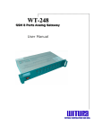
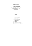
APORT series
IP to serial port Converter
Owner's Manual
APORT-006
CONTENTS
========
Chapter 1.
Introduction ............................................1
1-1 An Introduction to the APORT Converter ......................1
1-2 Hardware specifications .....................................1
1-3 Software specifications .....................................1
1-4 Serial port interface and order information .................2
Chapter 2. Configuring Hardware .....................................5
2-1 System Components ...........................................5
2-2 DIP switch setting ..........................................5
2-3 Installation Procedures .....................................5
Chapter 3. Operating mode setup in APORT ............................6
Chapter 4. Windows NT Installation (APORT mode only)................12
Chapter 5. Windows 2000/XP/2003/Vista Installation (APORT mode).....15
Chapter 6. Windows 7 System Installation (APORT mode)...............17
Chapter 7. Windows 2000/XP/2003/Vista Installation (TPORT mode).....19
Chapter 8. Windows 7 System Installation (TPORT mode)...............21
Chapter 9. UNIX/Linux system fix TTY GVMODEM driver Installation ...24
Chapter 10. SCO OpenServer real TTY RTTY driver Installation .......25
Chapter 11. Utility program to search APORT box ....................26
APPENDIX. A.
Pin Assignments and Cable Wiring ...................27
APPENDIX. B.
How to set APORT004 and APORT008 interface .........28
APPENDIX. C.
How to upgrade firmware in APORT ...................29
APPENDIX. D.
Troubleshooting procedure for APORT .................30
APPENDIX. E.
RAYON REPAIR PROCEDURE .............................31
-----Chapter 1----Introduction
1-1. An introduction to APORT Converter
APORT series Converter is one box to support 2/4/8 serial ports
to be accessed via one IP. We can have different operating mode
for each serial port to be accessed. It can be "virtual COM" port in
PC server. It can be TCP/IP or UDP/IP device in network environment.
For different model we can have RS232/RS422/RS485 interface with ground
isolated feature or not in serial port.
1-2. Hardware specification
*CPU: 100MHz 32bit MIPS CPU.
*Flash: 8MByte.
*SDRAM: 16MByte.
*Serial port: 1/2/4/8
with DB9 male connector.
*Ethernet port: 10/100Mbps.
*Console port: RS232 share with serial port 1.
*Power input: 5VDC power adaptor (UP110/UP220)
1-3 Software specification:
*Virtual COM driver for WIN NT/2000/XP/2003/Vista & WIN 7 system.
*real TTY RTTY driver for SCO Openserver system.
*fix TTY GVMODEM driver for Linux, SCO UNIX and other UNIX system.
*support TCP server mode to be connected.
*support RFC2217 function in TCP server TELNET mode.
*support TCP client mode to dedicated server.
*support UDP send mode to upto four dedicated server.
*support UDP receive mode to get from multiple host.
*support WEB setup mode.
*support TELNET setup mode.
*support CONSOLE setup mode.
–1–
1-4 Serial port interface and order information:
For different model we may have RS232, Ground isolated RS232 and Ground
isolated RS422/RS485 interface.
We may have following model name to specify different interface.
APORTxyz
x is port number of RS232 interface.
y is port number of Ground isolated RS232 interface.
z is port number of Ground isolated RS422/RS485 interface.
****Following model is for APORT100 box*****
APORT100P is 1 RS232 serial port with one pass-through RS232 port.
APORT010P is 1 Ground isolated RS232 serial port with one pass-through
RS232 port.
****Following model is for APORT200 box*****
APORT200 is 2 RS232 serial port.
APORT020 is 2 Ground isolated RS232 serial port.
APORT101 is 1 RS232(serial port) and 1 Ground isolated RS422/RS485
serial port(serial port 2).
iLOG101 is RS232(serial port 1) to Ground isolated RS422/RS485
(serial port 2) converter with two virtual COM port to monitor.
APORT201 is 1 Ground isolated RS422/RS485(port 2) with 1 pass-through
RS232 (port 1) and two remote IP access RS485 port.
–2–
****Following model is for APORT400 box*****
APORT400 is 4 RS232 serial port.
APORT040 is 4 Ground isolated RS232 serial port.
APORT202 is 2 RS232(serial port 1 & 2) and 2 Ground isolated RS422/RS485
serial port(serial port 3 & 4).
APORT301 is 3 RS232(serial port 1 & 2 & 3) and 1 Ground isolated RS422/RS485
serial port(serial port 4).
APORT031 is 3 Ground isolated RS232(serial port 1 & 2 & 3) and 1 Ground
isolated RS422/RS485 serial port(serial port 4).
APORT022 is 2 Ground isolated RS232(serial port 1 & 2) and 2 Ground isolated
RS422/RS485 serial port(serial port 3 & 4).
APORT004 is 4 Ground isolated RS422/RS485 serial port.
HMI
MODBUS
IP Network
IP
HMI
MODBUS
S2
S1
APORT100P
–3–
MODBUS
Device
****Following model is for APORT800 box*****
APORT800 is 8 RS232 serial port.
APORT602 is 6 RS232(serial port 1--6) and 2 Ground isolated RS422/RS485
serial port(serial port 7 & 8).
APORT620 is 6 RS232(serial port 1--6) and 2 Ground isolated RS232
serial port(serial port 7 & 8).
APORT080 is 8 Ground isolated RS232 serial port.
APORT044 is 4 Ground isolated RS232(serial port 1--4) and 4 Ground isolated
RS422/RS485 serial port(serial port 5--8).
APORT008 is 8 Ground isolated RS422/RS485 serial port.
NOTE: user can use DIP switch to set in RS422 or RS485 mode.
IP Network
IP
Remote PC
RS232
S1
S2
RS422/485
RS485 Device
Local PC
iLOG101
–4–
Chapter 2.
Configuring Hardware
2-1 System components
An APORT Converter includes following components:
*One APORT box.
*One UP110/UP220 power adaptor for APORT box.
*User manual and software CD.
2-2 DIP switch setting
We have one 4 bit DIP switch in APORT box.
*bit 1 is used to set serial port 1 connector as console port (ON location)
or normal serial port 1 application (OFF location).
*bit 2 is used to set APORT box in firmware upgrade mode (ON location)
or normal operating mode (OFF location).
*bit 3 is used to set serial port 3(APORT400 box) or 7(APORT800 box)
with RS422 interface (ON location)
or RS485 interface (OFF location).
NOTE:there are other special usage for this bit in APORT004 and
APORT008 box. Please check appendix B for more information.
*bit 4 is used to set serial port 2(APORT200 box),4(APORT400 box) or
8(APORT800 box) with RS422 interface (ON location)
or RS485 interface (OFF location).
NOTE:there are other special usage for this bit in APORT004 and
APORT008 box. Please check appendix B for more information.
NOTE: In normal operation condition bit 1 & 2 may set in OFF location.
2-3 Installation Procedures
One APORT box needs one LAN cable to connect with HUB.
The installation procedures are as follows:
(1) remove the power adaptor of your APORT box.
(2) Plug the LAN cable between APORT and HUB. In normal power on condition
the LED in LAN connector will light to indicate 10Mbps mode or 100Mbps
mode in use.
(3) Connect console cable between APORT and one terminal. The default
condition for console port will be 115200bps,no parity,8 data bit.
Console port is shared in serial port 1. If you did not need console
port, then you have serial port 1 in normal application. We have DIP
switch bit 1 in ON location for console application and OFF location
for normal serial port application for serial port 1 connector.
(4) Connect serial port cable between APORT and RS232/422/485 equipment.
(5) Set DIP switch bit 3 and bit 4 for RS422/RS485 interface in serial port
3/7 and serial port 2/4/8. ON is RS422 interface and OFF is RS485
interface. (APORT004 and APORT008 need to check appendix B).
(6) insert the power adaptor of APORT box.
(7) We can see the console out message in console terminal and the status
LED flash in APORT.
NOTE: user can only use UP110/UP220 power adaptor for 5VDC power supply.
If user used wrong power adaptor for higher voltage power supply
will destroy APORT.
–5–
Chapter 3
Operating mode setup in APORT
Because each serial port in APORT box can be used in different operating
mode to meet application environment. So we need to setup operating mode
in each serial port firstly.
3-1 Enter setup window
APORT support three types of method to setup the operating mode of each
serial port in APORT. We can use WEB to setup. We can use Telnet method
to setup. We can use console terminal to setup. We will have detail
description in following paragraph for WEB setup. The procedure for other
setup method is similar.
When you open your browser and type in the IP address of APORT (the
default IP address in factory is 192.168.1.254). Then you can see the
"Enter Network Password" dialogue box appeared. You can ignore the user
name and input the password directly (the default password in factory
is five one 11111).
3-2 Main setup window
When the password is entered and correct, the main setup window will
appear. In the left side of window you can see the function bar there.
Please click the function bar to enter function setup.
–6–
3-3 Connect setup window
Generally the first one we need to setup is "Connect setup". Because
we need to setup the dedicated IP address in APORT.
APORT support two types of IP address. One is Dynamic IP mode to get
IP address from DHCP server upon power on. We don't suggest this one.
Because you may have different IP address for different condition. And
it is not easy for you to maintain this condition for your application
software.
The other is static IP mode. We can setup the IP address, Netmask and
Gateway for dedicated value. Then it is easy for us to maintain in
application software.
3-4 Mode setup window
There are six operating mode for each serial port in APORT. Different
application environment may use suitable mode to meet their requirement.
APORT support GVMODEM Real TTY mode, COM Real TTY mode, TCP Server mode,
TCP Client mode, UDP Send/Receive and UDP Multi-Serial mode.
–7–
3-4-1 Real TTY mode
There are two types of Real TTY mode.
The first one is "COM Real TTY mode". In this mode we will use UDP packet
to communicate between PC and APORT box.In this mode you need to install
APORT mode virtual COM driver in Windows system or RTTY driver in SCO
Openserver UNIX system. The serial port in APORT to be set in this mode will
as be standard COM port in Windows system and standard TTY device in SCO UNIX
system. The serial port operation parameter(baud rate,data bit and stop bit
,parity bit, flow control mode) will be set in application program as
normal serial port in PC server. The application software in Windows system
and SCO Openserver system will be used in serial port of APORT box without
modification.
******NOTE: Our driver will use UDP port number 519 for "COM Real TTY mode".
User need to allow this UDP port number packet to transmit in firewall
setting.
The second one is "GVMODEM Real TTY mode". In this mode we will use TCP
packet to communicate between PC and APORT box. In this mode you need to
install driver in UNIX and LINUX system to have fixed virtual terminal
port (ttyp?). Because we can not modify the serial port parameter in
virtual terminal port. So user need to set the serial port parameter
in APORT firstly.
******NOTE: Our driver will use TCP port number 516 for "GVMODEM Real TTY
mode". User need to allow this TCP port number packet to transmit in
firewall setting.
3-4-2 TCP Server mode
TCP server mode will let the serial port in APORT box to be accessed
via Telnet or Socket connecting program. We must assign unique TCP port
number for each serial port. If user need to use standard TELNET
negotiation in connection procedure, we need to set "Telnet" mode in
setup. If user don't need the TELNET negotiation procedure in connection,
we need to set "TCP" mode in setup. Normally we will use "TCP" mode for
simple TCP connection application program.
We also support TPORT mode virtual com driver in Windows system to work
with "TCP Server mode" and "TCP mode". Then each serial port in APORT box
will be same as standard COM port in PC.
From firmware version 080318.hg later we can support RFC2217 function
in TCP server TELNET mode. User can set serial port configuration (baud
rate, flow control) based on RFC2217. We had tested in Tactical Software
COM redirector and CKermit 8.0 .
–8–
3-4-3 TCP Client mode
TCP Client mode will let APORT to connect with dedicated server with
assigned TCP port number. So we need to setup the Destination IP address
to connect and the target TCP port number. If user need to use standard
TELNET negotiation procedure in connection, we need to set "Telnet" mode
in setup. If user don't need the TELNET negotiation procedure in
connection, we need to set "TCP" mode in setup. Normally we will use "TCP"
mode for simple TCP connection application program.
Due to APORT need to connect with dedicated server and different
application program may have different requirement. So the timing for
APORT to connect with dedicated server is important. We can select
"startup" mode to let APORT will try to connect with dedicated server
upon power on. It means that we can transmit and receive data in serial
port upon APORT power on and connected. Sometimes we may need to know
the equipment connected in APORT's serial port ready to receive data or
not. In this requirement we can set "Receiving serial data" mode for
this serial port. It means that we need to wait the equipment connected
in serial port send data firstly. Then we start to connect with dedicated
server. After connection dedicated server will send data to APORT's serial
port. In this condition we can promise the equipment in serial port is
ready to receive data from remote server.
3-4-4 UDP mode
We need to set the UDP port number to receive UDP packet. We can also
setup the dedicated server to send serial port's data. Upon receiving the
data from serial port we can send UDP packet to upto four dedicated
server. So we can get data from multiple host and send to serial port.
But we can only get serial port data and send to upto four dedicated host.
User can assign the dedicated server's IP upto four host and left blank
for unused server.
3-4-5 UDP Multi-Serial mode
In traditional UDP mode we need to set unique UDP port number for each
serial port. We can not have different serial port in APORT box to have
same UDP port number. Because each serial port may have dedicated process
to handle the UDP packet. If we had same UDP port number in different
serial port, then we can not confirm which serial port's process will get
such packet. When we set in "UDP Multi-serial" mode, we can let multiple
serial port to have same UDP port number. The data from host can be
transmitted in multiple serial port simultaneously. In this mode we will
set HOST IP address and UDP port number in "connect setup window".
–9–
3-5 Serial port parameter setup
We can assign the serial port parameter in serial setup window. This
setup value will be used in GVMODEM Real TTY mode, TCP Server mode, TCP
Client mode and UDP mode.
3-6 Serial port connection status
We can check the connection status for each serial port. We only show
the connected serial port status. The disconnected port will be shown *
only. We will show the parameter of serial port with transmit data count
(TX Char) and receive data count (RX Char). But the data count is not
updated in real time basis. User need to click "status" again to update
the new data count.
3-7 Status of APORT system
We can check the status of APORT system. The displayed information
includes version of Firmware, Server name of APORT box, MAC address,
IP address, IP netmask and default Gateway address.
–10–
3-8 Reset and restart APORT
When we setup and modify some parameter in APORT, we will restart APORT
to let such value available. Sometimes we need to let APORT with factory
default parameter setting, we will click "Reset Default".
There are one special command in this field. We can reset TCP server mode
process. Due to some user may connect APORT in TCP server mode and there are
some problem in application environment. So we don't need to reset whole
APORT box (Because the boot procedure in Linux for APORT box is too long)
and just need to kill process to restart.
3-9 Change user name and password
In factory default condition we do not have user name setting and
password is five one 11111. We can setup the user name and password for
APORT. Next time you will need to use such value to enter setup screen.
3-10 Check network connection
When we need to check the LAN connection in APORT, we will use "ping"
command to known IP server for diagnosis. When such IP server is reachable
we will show "ping success". Or we may have "ping failure" to show.
–11–
Chapter 4
Windows NT Installation
4-1 Driver Installation
There are two components in Windows system virtual COM driver
installation. One is the driver. The other is the configuration file for
APORT.
In our CD you can find following files under NT4 driver directory.
a)APORTP.SYS
b)APORT_AP.EXE
c)APORTRUI.RAY
d)OEMSETUP.INF
====>
====>
====>
====>
APORTIOP driver for APORT400 box.
parameter setting file.
setup file for APORTIOP driver.
installation file for APORTIOP driver.
Please run "aport_ap.exe" file firstly. We can set the target total
port number of serial port need to be installed in this system.
Currently we can set 1 upto 64 serial ports. Then we need to set the
target IP address of APORT box and serial port number in this APORT
for each serial port. We can use "search" function to find the IP
address of each APORT box available in your network.
NOTE: aport_ap.exe will use multicast UDP packet to serach APORT box in
same IP sub-network. So we can not find the APORT box in different IP
sub-network. We need to use "aport_search.exe" to find all reachable APORT
box (Because we use broadcast UDP packet.
Now we can start to install our driver in "control panel". We will
choose "Network" and "add adaptor" (Please don't choose "add Software").
Then we can put our driver diskette or CD to install our APORTIOP
driver. Please use "<other> requires disk from manufacture" and specify
correct path for our driver.
Follow the normal procedure we can install the driver successfully.
Now you can find extra COM port in your system. But you must reboot
your system to let such COM port available.
******Please keep in mind that you must remove old version driver
firstly. Then you can install our new version driver.****************
–12–
4-2 How to set APORT as COM port.
When we need to set APORT as COM port in Windows system, we need to
run "aport_ap.exe".
When we run "aport_ap.exe", we will see the setup screen for serial
port. In the left side of screen is "Info" display for all APORT box
connected to LAN. We can double click "Search" to find all APORT box
connected to LAN. We will show all APORT box connected to LAN with IP
address and Server name. If we selected one IP address and double click,
we will see the "RTTY COM" mode in this APORT box. The serial port in
APORT box to be set in "RTTY COM" mode will be displayed as serial1
--serial16 (corresponding to serial port 1--4 in APORT400 box).
If you need to setup this APORT box, you can click "Setting" to connect
with APORT box via HTTP.
–13–
In the right side of screen is "Setting" display for virtual COM port
in Windows system. Here we can set serial1--serial64 to map in APORT
box. Because we can only have 16 serial port information displayed in
screen. We can use "<<" or ">>" column to set other serial port. In each
virtual COM port for Windows system we need to set the map value of
target APORT box's IP address and serial port number (1--16) in APORT. The
"PORT #" column in display will be assigned the serial port number in
APORT box.
When we had set the information of APORT for each serial port, we need
to save. In next boot procedure we can have virtual COM port available.
NOTE: In Windows NT system we can only work with "COM Real TTY mode" mode
in APORT box. For other WIN2000/XP/Visa and WIN7 system we may have APORT
mode virtual COM driver to work with " COM Real TTY mode" mode and TPORT
mode virtual COM driver to work with " TCP server mode" "TCP" mode in APORT
box.
–14–
Chapter 5
Windows 2000/XP/2003/Vista Installation (APORT mode)
5-1 Driver Installation
There are two components in APORT mode Windows system virtual COM driver
installation. One is the driver. The other is the configuration file for
APORT box.
In our CD you can find following files under WIN2000 driver directory.
a)APORT_AP.EXE ====> parameter setting file.
b)APORTB.SYS
====> APORTIOP box driver
c)APORTP.SYS
====> APORTIOP serial port driver
d)APORTRUI.DLL ====> setup file for APORTIOP driver.
e)A2KPORT1.INF ====> installation file for APORTIOP box driver.
f)A2KPORT2.INF ====> installation file for APORTIOP serial port driver.
g)APORT_Search.EXE ====> APORT box broadcast serach utility.
h)Ainstall.EXE ====> APORT box driver installation utility.
Please run "aport_ap.exe" file firstly. We can set the target port
number of serial ports to be installed in this system totally.
Currently we can set 1 upto 64 serial ports. Then we need to set the
target IP address of APORT box and serial port number in this APORT box
for each serial port. We can use "search" function to find the IP
address of each APORT box available in your network.
NOTE: aport_ap.exe will use multicast UDP packet to search APORT box. So
we can only find the APORT box with same IP sub-network. If we need to find
all reachable APORT box, then we need to use "aport_search.exe" utility.
We will use broadcast UDP packet to find all reachable APORT box.
Now we can start to install our driver in "control panel".
******Please keep in mind that you must remove old version driver
firstly. Then you can install our new version driver.****************
5-2 How to set APORT as COM port.
When we need to set APORT box's serial port as COM port in Windows system
, we need to run "aport_ap.exe" firstly.
When we run "aport_ap.exe", we will see the setup screen for serial
port. In the left side of screen is "Info" display for all APORT box
connected to LAN. We can double click "Search" to find all APORT box
connected to LAN. We will show all APORT box connected to LAN with IP
address and Server name. If we selected one IP address and double click,
we will see the "RTTY COM" mode in this APORT box. The serial port in
APORT box to be set in "RTTY COM" mode will be displayed as COM1--COM16
(corresponding to serial port 1--16 in APORT box). If you need to setup
this APORT box, you can click "Setting" to connect with APORT box via
HTTP. Then we can modify the serial port mode of each serial port.
–15–
In the right side of screen is "Setting" display for virtual COM port
in Windows system. Here we can set serial1--serial64 to map in APORT
box. Because we can only have 16 serial port information displayed in
screen. We can use "<<" or ">>" column to set other serial port. In each
virtual COM port for Windows system we need to set the map value of
target APORT box's IP address and serial port number (1--16). The
"PORT #" column in display will be assigned the serial port number in
APORT box(In each APORT box we have serial port 1--16).
When we had set the information of APORT for each serial port, we need
to save. In next boot procedure we can have virtual COM port available.
5-3.Installation procedure in WIN2000/Vista system
a)We just need to run "ainstall.exe" to install our driver.
b)After card driver installed, each COM port's driver will be installed
automatically.
c)After the driver installation procedure is finished, we can check
"Device Manager" to find the COM port number for each serial port
in APORT. It will be no confliction with other device. Because
P&P manager can handle such condition. If the COM port number
assigned value did not meet our target, we can also modify such
value in "RAYON APORT IOP Driver" setup.
5-4.Installation procedure in WIN XP system
a)We just need to run "ainstall.exe" to install our driver.
I have already connected the hardware".
b)After card driver installed, each COM port's driver will be asked to
install one by one.
c)After the driver installation procedure is finished, we can check
"Device Manager" to find the COM port number for each serial port
in APORT. It will be no confliction with other device. Because
P&P manager can handle such condition. If the COM port number
assigned value did not meet our target, we can also modify such
value in "RAYON APORT IOP Driver" setup.
5-5.Special consideration in Windows Vista system
a)Because Vista system may have "firewall" to block IP access to
APORT box. We can use the "search" function in "aport_ap.exe"
to find APORT box. The "firewall" will ask us to enable APORT
IP address access or not. We must enable APORT IP access. Then
our APORTIOP driver will be run without problem.
–16–
Chapter 6
Windows 7 System Installation (APORT mode)
6-1 Driver Installation
There are two components in APORT mode Windows system virtual COM driver
installation. One is the driver. The other is the configuration file for
APORT box.
In our CD you can find following files under WIN2000 driver directory.
a)APORT_AP.EXE ====> parameter setting file.
b)APORTB.SYS
====> APORTIOP box driver
c)APORTP.SYS
====> APORTIOP serial port driver
d)APORTRUI.DLL ====> setup file for APORTIOP driver.
e)A2KPORT1.INF ====> installation file for APORTIOP box driver.
f)A2KPORT2.INF ====> installation file for APORTIOP serial port driver.
g)APORT_Search.EXE ====> APORT box broadcast serach utility.
h)Ainstall.EXE ====> APORT box driver installation utility.
Please run "aport_ap.exe" file firstly. We can set the target port
number of serial ports to be installed in this system totally.
Currently we can set 1 upto 64 serial ports. Then we need to set the
target IP address of APORT box and serial port number in this APORT box
for each serial port. We can use "search" function to find the IP
address of each APORT box available in your network.
NOTE: aport_ap.exe will use multicast UDP packet to search APORT box. So
we can only find the APORT box with same IP sub-network. If we need to find
all reachable APORT box, then we need to use "aport_search.exe" utility.
We will use broadcast UDP packet to find all reachable APORT box.
NOTE: We must use "Run As Administrator" to run "aport_ap.exe".
6-2 How to set APORT as COM port.
When we need to set APORT box's serial port as COM port in Windows system
, we need to run "aport_ap.exe" (with "Run as Administrator" right)firstly.
When we run "aport_ap.exe", we will see the setup screen for serial
port. In the left side of screen is "Info" display for all APORT box
connected to LAN. We can double click "Search" to find all APORT box
connected to LAN. We will show all APORT box connected to LAN with IP
address and Server name. If we selected one IP address and double click,
we will see the "RTTY COM" mode in this APORT box. The serial port in
APORT box to be set in "RTTY COM" mode will be displayed as COM1--COM16
(corresponding to serial port 1--16 in APORT box). If you need to setup
this APORT box, you can click "Setting" to connect with APORT box via
HTTP. Then we can modify the serial port mode of each serial port.
–17–
In the right side of screen is "Setting" display for virtual COM port
in Windows system. Here we can set serial1--serial64 to map in APORT
box. Because we can only have 16 serial port information displayed in
screen. We can use "<<" or ">>" column to set other serial port. In each
virtual COM port for Windows system we need to set the map value of
target APORT box's IP address and serial port number (1--16). The
"PORT #" column in display will be assigned the serial port number in
APORT box(In each APORT box we have serial port 1--16).
When we had set the information of APORT for each serial port, we need
to save. In next boot procedure we can have virtual COM port available.
NOTE: We must run "aport_ap.exe" with "Run As Administaror" right. So we can
save our configuration file to be used in driver installation procedure. If
we did not run with "Run As Administrator" right, then we will have wrong
configuration file to be used.
6-3.Installation procedure in Windows 7 system
a)We just need to run "ainstall.exe" to install our driver.
b)After card driver installed, each COM port's driver will be installed
automatically.
c)After the driver installation procedure is finished, we can check
"Device Manager" to find the COM port number for each serial port
in APORT. It will be no confliction with other device. Because
P&P manager can handle such condition.
d)But we may find the COM port number for each serial port do not have
correct relationship with physical location. For example, we may have
4 serial ports to be specified in aport_ap.exe. In WIN2000, XP, Vista
we may have correct relationship for COM3--COM6 in serial port 1--4.
In WIN7 system we may have random COM port number for serial port 1--4.
It is not easy for user to know which COM port number is which
serial port. Fortunately, we have SETUP in APORT IOP's driver to
set COM port start number for serial port 1--4. In "control panel"
"device manager" you can select APORT IOP in "multi-port serial adapters"
and double strike mouse to enter "Properties" "SETUP" screen. Then you can
modify COM port start number to other value. So we can have serial
port 1--4 with corresponding COM port sequentially.
You can have extra COM port with correct COM port number in next boot.
–18–
Chapter 7
Windows 2000/XP/2003/Vista Installation (TPORT mode)
7-1 Driver Installation
There are two components in TPORT mode Windows system virtual COM driver
installation. One is the driver. The other is the configuration file for
APORT box.
In our CD you can find following files under TPORT driver directory.
a)TPORT_AP.EXE ====> parameter setting file.
b)TPORTB.SYS
====> TPORTIOP box driver
c)TPORTP.SYS
====> TPORTIOP serial port driver
d)TPORTRUI.DLL ====> setup file for TPORTIOP driver.
e)T2KPORT1.INF ====> installation file for TPORTIOP box driver.
f)T2KPORT2.INF ====> installation file for TPORTIOP serial port driver.
g)TPORT_Search.EXE ====> APORT box broadcast serach utility.
h)Tinstall.EXE ====> TPORT driver installation utility.
Please run "tport_ap.exe" file firstly. We can set the target port
number of serial ports to be installed in this system totally.
Currently we can set 1 upto 64 serial ports. Then we need to set the
target IP address of APORT box and TCP port number of this serial port
for each serial port. We can use "search" function to find the IP
address of each APORT box available in your network.
NOTE: tport_ap.exe will use multicast UDP packet to search APORT box. So
we can only find the APORT box with same IP sub-network. If we need to find
all reachable APORT box, then we need to use "tport_search.exe" utility.
We will use broadcast UDP packet to find all reachable APORT box.
******Please keep in mind that you must remove old version driver
firstly. Then you can install our new version driver.****************
7-2 How to set APORT as COM port.
When we need to use TPORT driver to set APORT box's serial port as
COM port in Windows system , we need to run "tport_ap.exe" firstly.
When we run "tport_ap.exe", we will see the setup screen for serial
port. In the left side of screen is "Info" display for all APORT box
connected to LAN. We can double click "Search" to find all APORT box
connected to LAN. We will show all APORT box connected to LAN with IP
address and Server name. If we selected one IP address and double click,
we will see the "RTTY COM" mode in this APORT box. The serial port in
APORT box to be set in "RTTY COM" mode will be displayed as COM1--COM16
(corresponding to serial port 1--16 in APORT box). If you need to setup
this APORT box, you can click "Setting" to connect with APORT box via
HTTP. Then we can modify the serial port mode of each serial port. When
we need to use TPORT mode virtual COM driver, we need to set in "TCP server
mode" and "TCP mode". Please remember the TCP port number assigned for this
serial port.
–19–
In the right side of screen is "Setting" display for virtual COM port
in Windows system. Here we can set serial1--serial64 to map in APORT
box. Because we can only have 16 serial port information displayed in
screen. We can use "<<" or ">>" column to set other serial port. In each
virtual COM port for Windows system we need to set the map value of
target APORT box's IP address and TCP port number assigned for this serial
port. The "PORT #" column in display will be assigned the TCP port number
assigned in APORT box.
NOTE: When we need to use TPORT mode virtual COM driver in Windows. We must
set serial port mode in APORT box as "TCP Server mode" and "TCP mode". And
we must assign one TCP port number for this serial port. (The default value
is 10001--10016 for serial port 1--16).
When we had set the information of APORT for each serial port, we need
to save. In next boot procedure we can have virtual COM port available.
7-3.Installation procedure in WIN2000/Vista system
a)We just need to run "tinstall.exe" to install our driver.
b)After card driver installed, each COM port's driver will be installed
automatically.
c)After the driver installation procedure is finished, we can check
"Device Manager" to find the COM port number for each serial port
in APORT. It will be no confliction with other device. Because
P&P manager can handle such condition. If the COM port number
assigned value did not meet our target, we can also modify such
value in "RAYON TPORT IOP Driver" setup.
7-4.Installation procedure in WIN XP system
a)We just need to run "tinstall.exe" to install our driver.
I have already connected the hardware".
b)After card driver installed, each COM port's driver will be asked to
install one by one.
c)After the driver installation procedure is finished, we can check
"Device Manager" to find the COM port number for each serial port
in APORT. It will be no confliction with other device. Because
P&P manager can handle such condition. If the COM port number
assigned value did not meet our target, we can also modify such
value in "RAYON TPORT IOP Driver" setup.
7-5.Special consideration in Windows Vista system
a)Because Vista system may have "firewall" to block IP access to
APORT box. We can use the "search" function in "tport_ap.exe"
to find APORT box. The "firewall" will ask us to enable APORT
IP address access or not. We must enable APORT IP access. Then
our TPORTIOP driver will be run without problem.
–20–
Chapter 8
Windows 7 System Installation (TPORT mode)
8-1 Driver Installation
There are two components in TPORT mode Windows system virtual COM driver
installation. One is the driver. The other is the configuration file for
APORT box.
In our CD you can find following files under TPORT driver directory.
a)TPORT_AP.EXE ====> parameter setting file.
b)TPORTB.SYS
====> TPORTIOP box driver
c)TPORTP.SYS
====> TPORTIOP serial port driver
d)TPORTRUI.DLL ====> setup file for TPORTIOP driver.
e)T2KPORT1.INF ====> installation file for TPORTIOP box driver.
f)T2KPORT2.INF ====> installation file for TPORTIOP serial port driver.
g)TPORT_Search.EXE ====> APORT box broadcast serach utility.
h)Tinstall.EXE ====> TPORT driver installation utility.
Please run "tport_ap.exe" file firstly. We can set the target port
number of serial ports to be installed in this system totally.
Currently we can set 1 upto 64 serial ports. Then we need to set the
target IP address of APORT box and serial port number in this APORT box
for each serial port. We can use "search" function to find the IP
address of each APORT box available in your network.
NOTE: tport_ap.exe will use multicast UDP packet to search APORT box. So
we can only find the APORT box with same IP sub-network. If we need to find
all reachable APORT box, then we need to use "tport_search.exe" utility.
We will use broadcast UDP packet to find all reachable APORT box.
NOTE: We must use "Run As Administrator" to run "tport_ap.exe".
8-2 How to set APORT as COM port.
When we need to set APORT box's serial port as COM port in Windows system
, we need to run "tport_ap.exe" (with "Run as Administrator" right)firstly.
When we run "tport_ap.exe", we will see the setup screen for serial
port. In the left side of screen is "Info" display for all APORT box
connected to LAN. We can double click "Search" to find all APORT box
connected to LAN. We will show all APORT box connected to LAN with IP
address and Server name. If we selected one IP address and double click,
we will see the "RTTY COM" mode in this APORT box. The serial port in
APORT box to be set in "RTTY COM" mode will be displayed as COM1--COM16
(corresponding to serial port 1--16 in APORT box). If you need to setup
this APORT box, you can click "Setting" to connect with APORT box via
HTTP. Then we can modify the serial port mode of each serial port. When
we need to use TPORT mode virtual COM driver in Windows 7 system we need
to set APORT's serial port mode in "TCP server mode" and "TCP mode". Then
we will assign one TCP port number for this serial port.
–21–
In the right side of screen is "Setting" display for virtual COM port
in Windows system. Here we can set serial1--serial64 to map in APORT
box. Because we can only have 16 serial port information displayed in
screen. We can use "<<" or ">>" column to set other serial port. In each
virtual COM port for Windows system we need to set the map value of
target APORT box's IP address and TCP port number assigned for this serial
port. The "PORT #" column in display will be assigned the TCP port number in
APORT box.
When we had set the information of APORT for each serial port, we need
to save. In next boot procedure we can have virtual COM port available.
NOTE: We must run "tport_ap.exe" with "Run As Administaror" right. So we can
save our configuration file to be used in driver installation procedure. If
we did not run with "Run As Administrator" right, then we will have wrong
configuration file to be used.
–22–
8-3.Installation procedure in Windows 7 system
a)We just need to run "tinstall.exe" to install our driver.
b)After card driver installed, each COM port's driver will be installed
automatically.
c)After the driver installation procedure is finished, we can check
"Device Manager" to find the COM port number for each serial port
in TPORT. It will be no confliction with other device. Because
P&P manager can handle such condition.
d)But we may find the COM port number for each serial port do not have
correct relationship with physical location. For example, we may have
4 serial ports to be specified in tport_ap.exe. In WIN2000, XP, Vista
we may have correct relationship for COM3--COM6 in serial port 1--4.
In WIN7 system we may have random COM port number for serial port 1--4.
It is not easy for user to know which COM port number is which
serial port. Fortunately, we have SETUP in TPORT IOP's driver to
set COM port start number for serial port 1--4. In "control panel"
"device manager" you can select TPORT IOP in "multi-port serial adapters"
and double strike mouse to enter "Properties" "SETUP" screen. Then you can
modify COM port start number to other value. So we can have serial
port 1--4 with corresponding COM port sequentially.
You can have extra COM port with correct COM port number in next boot.
–23–
Chapter 9
UNIX/Linux system fix TTY GVMODEM driver Installation
9-1. Procedure in APORT box
a) we need to set serial port in REALTTY mode and set in "GVMODEM".
b) we need to set serial port protocol for application.
9-2. Procedure in UNIX & LINUX system
a) you may get "gvmodem_???.tar" driver package from CD.
It is gvmodem_linux.tar for Linux system directory.
It is gvmodem_sco.tar for SCO UNIX system directory.
b) Please create one directory "/etc/gtstcpd" for this driver.
c) please extract "gvmodem_???.tar" in this directory
tar xvf gvmodem_???.tar
(it may be gvmodem_linux.tar for LINUX)
d) Now, we need to modify "gtstcpd.cf" file. This is the most important
thing in driver. Because we need to fix every pseudo TTY device to
its IP address and serial port number for APORT box.
e) You need to input all data as following format.
R
/dev/ttyp??
GPORT_IP
GPORT_SERIAL_PORT_NUMBER
For example, you need to set the serial port number 1--4 as device
name /dev/ttyp[1--4] and your APORT with IP 192.168.1.3. So you
may have following text line in "gtstcpd.cf" file.
R
R
R
R
/dev/ttyp1
/dev/ttyp2
/dev/ttyp3
/dev/ttyp4
192.168.1.3
192.168.1.3
192.168.1.3
192.168.1.3
1
2
3
4
f) Now you can run following command to enable "gvmodem" daemon to fix
the pseudo TTY for each serial port.
./gtstcpd.rc
start
g) Then you can use following command to confirm every process enabled.
ps -ef | grep gvmodem
h) So you can modify "/etc/inittab" to add "ttyp??" device and enable.
i) If you did not need to run such driver, you can run following command
to stop it.
./gtstcpd.rc
stop
j) You can also let "gtstcpd" to be run in boot procedure.
In Linux system it may be put in /etc/rc.d/rc.sysinit
In SCO system it may be put in /etc/rc2.d
###########################################################################
For more information or problem you can send mail to [email protected]
###########################################################################
–24–
Chapter 10
SCO OpenServer real TTY RTTY driver Installation
10-1. Procedure in APORT
a) we need to set serial port in REALTTY mode and set in "COM".
10-2. Procedure in SCO UNIX system
a) you may get "rtty100.tar" driver package from CD.
b) Please create one directory for this driver.
ex., /etc/gport
c) please extract "rtty100.tar" in this directory
tar xvf rtty100.tar
d) you will have "rtty100" directory in this directory.
e) please goto "rtty100" directory and run "install" to install driver.
f) you will be asked to modify "nasd.rc" file. In this file you need to
specify IP address for each APORT. You will have box number for
each APORT. We can accept 1--16. It means that we can have upto
16 APORT in this SCO UNIX system.
g) after driver installation we will have "S99nasd" process in directory
/etc/rc2.d and it will be run automatically in boot procedure.
h) if you did not need to enable REALTTY driver now, you can remove above
process. When you need to enable REALTTY driver later, you can run
/etc/nasd.rc to activate.
10-3. The device name for APORT
a) the device name for each serial port in APORT is
/dev/tty[01--16][a--p]
b) [01--16] is the box number defined in nasd.rc file
c) [a--b]
[a--d]
[a--h]
[a--p]
is
is
is
is
the
the
the
the
serial
serial
serial
serial
port
port
port
port
1--2 in APORT200.
1--4 in APORT400.
1--8 in APORT800.
1--16 in GPORT116.
d) ex., we have one APORT with IP address 192.168.1.3 to be defined
in "nasd.rc" file as "1" box number. So we have following device
name for each serial port in APORT.
serial port 1 is /dev/tty01a
serial port 2 is /dev/tty01b
serial port 3 is /dev/tty01c
serial port 4 is /dev/tty01d
We may have following command line in "nasd.rc" file.
/etc/nasd 192.168.1.3 1 &
###########################################################################
For more information or problem you can send mail to [email protected]
###########################################################################
–25–
Chapter 11
Utility program to search APORT box
11-1. aport_ap.exe usage
a) "aport_ap.exe" will be used to setup the configuration of virtual
COM port in Windows system.
b) We can also use this utility to find the APORT available in the same
IP sub-network. Because we use multicast UDP packet to search APORT box, so
we can find the APORT box with same IP segment.
11-2. aport_search.exe usage
a) Because "aport_ap.exe" can only find the APORT box with same IP
sub-network. When we have one APORT box with unknown IP address. Then we
may not find such APORT box in "aport_ap.exe". So we will use "aport_search"
to find all reachable APORT box. Because we use broadcast UDP packet to serach
APORT box, so we can find all reachable APORT box.
b) Then we can modify IP address of such APORT box with same IP segment
as this PC. So we can use this APORT box in our application.
11-3. tport_ap.exe usage
a) "tport_ap.exe" will be used to setup the configuration of virtual
COM port in Windows system.
b) We can also use this utility to find the APORT available in the same
IP sub-network. Because we use multicast UDP packet to search APORT box, so
we can find the APORT box with same IP segment.
11-4. tport_search.exe usage
a) Because "tport_ap.exe" can only find the APORT box with same IP
sub-network. When we have one APORT box with unknown IP address. Then we
may not find such APORT box in "tport_ap.exe". So we will use "tport_search"
to find all reachable APORT box. Because we use broadcast UDP packet to serach
APORT box, so we can find all reachable APORT box.
b) Then we can modify IP address of such APORT box with same IP segment
as this PC. So we can use this APORT box in our application.
–26–
Appendix A
Pin assignements and Cable Wiring
A-1:
APORT serial port DB9 male connector Pin Assignment
=============================================================
Pin #
| RS232 mode
| RS422/485 mode
------------------------------------------------------------1
|
DCD (input)
| PULL------------------------------------------------------------2
|
RXD (input)
| RXD+
------------------------------------------------------------3
|
TXD (output)
| TXD+
------------------------------------------------------------4
|
DTR (output)
| TXD------------------------------------------------------------5
|
GND
| isolated GND
------------------------------------------------------------6
|
DSR (input)
| RXD------------------------------------------------------------7
|
RTS (output)
| PULL+
------------------------------------------------------------8
|
CTS (input)
|
------------------------------------------------------------9
|
RI (input)
|
------------------------------------------------------------Note: In RS485 mode we need to short pin 2 & 3 as DATA+ signal and
short pin 4 & 6 as DATA- signal.
Note: In RS485 mode we have 10K ohm pull up and pull low resistor for
DATA+ and DATA- signal. If user needed 680 ohm pull up and
pull low resistor,then short pin 7 & 2 and short pin 1 & 6.
–27–
Appendix B
How to set APORT004 and APORT008 interface
==========================================
B-1. DIP switch in front panel
a)In front panel of APORT004/008 box we can see one 4bit DIP switch.
b)In bit 1 location we can use this bit to let serial port 1 of APORT
box to be used as console setup port (DIP switch ON) or normal serial
port application (DIP switch OFF). (factory default condition is OFF)
c)In bit 2 location we can use this bit to let APORT box to enter
"firmware upgrade" mode upon power on (DIP switch ON) or enter
"normal" application mode (DIP switch OFF). (default OFF).
d)In bit 3 location we can use this bit to let all serial port in APORT
box to be RS422 interface (DIP switch ON) or RS485 interface (DIP
switch OFF). We also need to let bit 4 location in ON condition for
this application environment. (default OFF).
e)In bit 4 location we use this bit to let all serial ports in APORT box
as RS422/RS485 interface set by bit 3 (DIP switch ON). Or each serial
port in this box can be set in RS422 or RS485 interface independently.
(DIP switch OFF).
(default OFF).
B-2. DIP switch in PCB
a) When we need to set each serial port in APORT004/APORT008 to have
RS422 or RS485 interface independently. We need to set bit 4 location
in front panel's DIP switch in OFF condition.
b) We need to open the cabinet of APORT box. In APORT004 PCB we can have
one 4bit DIP switch in SW3 location. We can set serial port in RS422
interface (DIP switch ON) or RS485 interface (DIP switch OFF). In
APORT008 PCB we can have one 4bit DIP switch in SW3 location to set
interface type for serial port 1--4. And there are another 4bit DIP
switch in SW2 location to set interface type for serial port 5--8.
c) If we needed to set each serial port's interface type independently,
we must set bit 4 location in front panel's DIP switch in OFF.
d) If we needed to set all serial port's interface in same condition,
we can set bit 4 location in front panel's DIP switch in ON. And we
can use bit 3 location in front panel's DIP switch for target
interface type.
B-3. Factory default condition
a) In factory default condition we have all bit OFF in front panel's
DIP switch. So we will let DIP switch in PCB to define each serial
port's interface type.
b) In factory default condition we have all bit OFF in PCB's SW2 and SW3
location. So we will have RS485 interface type for each serial port.
c) So we will have all serial ports in RS485 application environment.
For other application environment user may need to set DIP switch to
meet target application environment.
B-4. How to use serial port in RS485 environment
a) We have TX+ , TX- , RX+ , RX- , GND signal in each serial port DB9
connector.
b) When you need to use 2 wire RS485 application, you need to short TX+
and RX+ as DATA+ signal. You need to short TX- and RX- as DATA- signal.
–28–
Appendix C
How to upgrade firmware in APORT
===================================
C-1. Procedure in APORT box.
a)prepare one console terminal to connect with console port in APORT
serial port 1 connector. Set bit 1 of DIP switch in ON location.
b)we need to set this terminal in 115200bps, no parity, 8 data, 1stop.
c)set bit 2 of DIP switch in ON location. Insert power adaptor to
turn on the power for APORT to enter firmware upgraded mode.
d)When you see "Enter Wait HG Command Mode ....." message in your console
terminal, you can start firmware upgrade procedure.
NOTE: If you did not have console terminal to connect, you can not confirm
APORT is ready in firmware upgraded mode. You need to wait about
one minutes to enter firmware upgrade mode.
NOTE: APORT is in tftp server mode and wait tftp client device to send
firmware image file to APORT.
NOTE: APORT is in tftp server mode with IP 192.168.1.254. Please confirm
there are no other device with this IP and your system can reach
this IP address.
C-2. Procedure in Windows environment
a) Please set your Windows system with IP address in 192.168.1.111
b)you may get new firmware image from CD or your supplier.
It may have file name as aport400_091102.hg
c)you may have our utility with file name as "wftp8.exe" in our CD's
firmware directory.
d)you just need to run "wftp8.exe".
e)you can specify to download the new firmware image file
"aport400_091102.hg" and start to send.
NOTE: our APORT in this firmware upgraded condition always have IP
address in 192.168.1.254. So it is good for this environment just
APORT and Windows system in LAN.
C-3. Procedure in UNIX/LINUX environment
a) Because APORT is in tftp server condition, so we just need to run
tftp client procedure.
b) tftp 192.168.1.254
tftp> binary
tftp> put aport400_091102.hg
C-4. How to confirm you have new firmware version
a) We can enter WEB setup (the new firmware may have default IP address
192.168.1.254 and password 11111).
b) In "system" "status" you can see the firmware version display.
c) Or you can see in "console" setup mode.
###########################################################################
For more information or problem you can send mail to [email protected]
###########################################################################
–29–
Appendix D
Troubleshooting procedure for APORT
======================================
1. Please confirm your APORT with correct power input.
We can check the POWER LED in front panel turned ON upon power on.
We can only use 5VDC switching power adaptor. For other voltage power
adaptor may damage APORT PCB and IC.
2. Please connect one terminal to console port.
Because APORT box is based on Linux system. So we can see the console
out message for Linux boot procedure. You can enter setup screen in
normal condition.
3. Please confirm the LAN connection is reachable.
Generally we will use "ping" function to confirm.
4. The serial port data transmission is correct or not.
In each serial port we have LED display to indicate data transmit or
receive condition.
5. In WEB setup screen we can check the serial port data transmission
condition.
6. Q: When we use "Hyperterm" as console port terminal, we can not have
correct display.
A: Please use "Hyperterm" as following setting
Function,arrow & ctrl key ===> Terminal keys.
Backspace Key ====> Ctrl+H
VT100 emulation
ASCII sending ====> no special setting
ASCII receiving ====> no special setting.
In our CD you can find "Teraterm" terminal emulation program in
\utility directory. Please install this software to run "Teraterm"
for termianl application.
–30–
Appendix E
RAYON REPAIR PROCEDURE
==========================
1. RETURN MATERIAL AUTHORIZATION (RMA or RA)
RAYON requires that you provide the following information :
* Model number
* RAYON serial number
* The reason for returning the products
######################################################################
# We strongly suggest that you can check with RAYON by E_mail before#
#you can confirm the reason for returning the products. Because some #
#problem may be due to wrong software usage or setup only.
#
#
#
[email protected]
######################################################################
* Your purchase-order number
You will be given the following information from your RAYON Service
Representative:
* Your Return Material Authorization Number (RMA or RA Number)
* Information regarding applicable charges
* The address to which you will return the products
2. REPAIR CHARGES
All RAYON products have a one year warranty. Products that are damaged or
modified are not covered.
This limited warranty covers defects in materials and workmanship in your
RAYON-branded hardware products. This limited warranty does not cover
problems that result from:
*external causes such as accident,abuse,misuse,or problems with
electrical power.
*Servicing not authorized by us.
*Usage that is not in accordance with product instructions.
*Failure to follow the product instructions or failure to perform
preventive maintenance.
Products that are covered under the original warranty and that are found
defective by RAYON will be repaired at no cost. A standard handling and
testing charge will be assessed for products returned for warranty repair
that are found to be operating properly.
Products that are no longer covered under warranty will be repaired, if
deemed repairable, for a flat rate charge regardless of the repair work
required.
Please contact the nearest RAYON Service Center for current pricing
information.
–31–
UTS4 8 5
USB to Serial Port Converter
S
Su
up
pp
po
orrtt ffo
ou
urr p
po
orrttss iin
no
on
nee b
bo
oxx
S
Su
up
pp
po
orrtt ttw
wo
oR
RS
S223322 p
po
orrttss
S
Su
up
pp
po
orrtt ttw
wo
oG
Grro
ou
un
nd
d iisso
ollaatteed
dR
RS
S442222//448855 p
po
orrtt
P
Po
ow
weerrffu
ull aan
nd
dF
Flleexxiib
bllee ffo
orr rreed
du
un
nd
daan
nccyy u
ussaag
gee
★ Support USB2.0 device controller
★ 512 Bytes FIFO for data transfer
★ Support LED display for each port
★ two RS232 for local connection
★ two Ground Isolated RS422 and RS485 selectable port for
remote connection.
★ Auto Data Direction Control on RS485 mode
★ Support screw terminal in RS422/485 port
★ Support bus powered mode
★ Use MOSCHIP MCS7840 chip
UTS004
USB to Serial Port Converter
◆ Support four ports in one box
◆ Support four ground isolated
RS422/485 port
◆ Powerful and Flexible for
redundancy usage
★Support USB2.0 device controller
★512 Bytes FIFO for data transfer
★Support LED display for each port
★four ground Isolated RS422 and RS485 selectable
port for remote connection.
★Auto Data Direction Control on RS485 mode
★Support bus powered mode
★Use MOSCHIP MCS7840 chip
APORT Box
Support
1 Port Series
APORT100P
APORT010P
2 Port Series
APORT200
APORT101
APORT020
ILOG101
APORT201
4 Port Series
APORT400
APORT004
APORT040
APORT022
8 Port Series
APORT800
APORT620
APORT080
APORT602
APORT008
APORT044