1
D-ILA Projector
Projector
D-ILA
DLA-G10U/E Ceiling Mount
ProjecteurD-ILA
D-ILA
Projecteur
Monture au plafond pour DLA-G10U/E
EF-G10CG
CONTENTS
Safety Precautions ....................................................................2
Unit Dimensions ........................................................................4
Names of Parts .........................................................................5
Installation .................................................................................6
Parts List ...................................................................................7
How to Install.............................................................................8
How to Prevent Dropping ........................................................10
Installing the Ceiling Mount on the Ceiling ..............................11
Mounting the Projector on the Ceiling Mount ..........................12
Projection Angle Adjustments .................................................13
Replacing the Lamp and Filter ................................................14
Specifications ..........................................................................15
Table des matières
Consignes de sécurité.............................................................16
Dimensions de l’appareil .........................................................18
Nom des pièces ......................................................................19
Installation ...............................................................................20
Liste des pièces ......................................................................21
Comment installer ...................................................................22
Pour empêcher la chute ..........................................................24
Installation de la monture au plafond sur le plafond................25
Montage du projecteur sur la monture au plafond ..................26
Réglage de l’angle de projection.............................................27
Remplacement de la lampe et du filtre....................................28
Fiche technique.......................................................................29
When installing, also read the DLA-G10U/E instruction manual.
Thank you for purchasing this product.
Before using your new purchase, please read this instruction manual thoroughly. And, after
reading, be sure to store this instruction manual in a safe place for future reference.
Pour l’installation, se reporter également au mode d’emploi du DLA-G10U/E.
Nous vous remercions d’avoir acheté ce produit.
Avant d’utiliser votre projecteur, veuillez lire attentivement toutes les instructions de ce
manuel. Puis, après l’avoir lu, rangez-le en lieu sûr de façon à pouvoir vous y reporter.
Instruction Manual
Mode d’oemploi
BHU30002-028-01
English
PRECAUTIONS FOR SAFE AND PROPER USE
Regarding Symbol Indications
Numerous symbols are employed as indication in the precautions for safety, precautions for handling, and in the indication to
the products. These are designed to prevent in advance any possible infliction of injury on you and other individuals and the
damage of properties through the proper use of the product. The symbols and meanings are shown below. Grasp the contents
of the symbols completely before reading this manual.
WARNING
CAUTION
This represents the contents in which the probabilities for death or serious
injury are assumed if this symbol indication is ignored and the product is
erroneously handled.
This represents the contents in which the probabilities for injury to be inflicted
are assumed and the contents in which material damages to be sustained are
assumed if this symbol indication is ignored and the product is erroneously
handled.
Examples of Symbol Indications
This symbol informs you of the presence of the contents that demands caution (including danger and warning).
Specifically prohibited contents (caution against electric shock in case of the left symbol) are illustrated in the
symbol.
This symbol informs you of prohibited actions. Specifically prohibited contents (prohibition of disassembly
in case of the left symbol) are illustrated in the symbol and its vicinity.
This symbol informs you of the contents that forces you to take some action or gives you some guidelines or
instructions. Specific contents of instructions (unplug the power cord from the outlet in case of the left symbol)
are illustrated.
2
To assure safety, special techniques are
required for installation. The customer should
never perform this work. Consult your dealer
concerning installation.
Provide sufficient reinforcement when the
ceiling on which this product will be installed is
too weak. Install so as to prevent any safety
related problems. If the ceiling is too weak or
the installation is improperly performed, this
product could possibly drop and cause injury
or damage.
CAUTION
When replacing the lamp or filter, provide a
solid footing from which a comfortable posture
can be adopted. Working with an unstable
footing or in an uncomfortable posture can
result in injury or damage. When the
installation work is difficult, lower to a safe
height and call a professional installer.
Never suspend or hang objects from the
ceiling mount. An excessive load can cause
the ceiling mount to fall and result in injury or
damage.
This product is to be used only for ceiling
mounting. Do not use it for any other
application. And never make alterations
because this can cause an accident.
English
WARNING
CAUTION
Do not install in locations subject to low or high
temperatures, near a kitchen table or
humidifier, or where there is oil smoke or water
vapor. This can result in projector malfunction,
deterioration of image quality, fire or electrical
shock.
Do not install the projector in a box or other
closed space where the hot air from the
projector cannot be exhausted. Do not block
the exhaust port of the projector. Projector
overheating can result in malfunction, loss of
image quality or electrical shock.
Permissible temperature range:
5 - 35 degrees C
Permissible humidity range:
20% - 80%, no condensation.
HANDLING PRECAUTIONS
Please observe the following cautions to
prevent malfunction or deterioration of the
product.
Do not install where there is danger of contact with
excessive dust, oil smoke, tobacco smoke, water
vapor. etc. These will adhere to the lens, liquid crystal
panel, mirror, etc., and result in blurred or dark
images.
Install in a room that can be darkened to prevent
direct sunlight, illumination or reflected light on the
screen. Such light will cause the images to appear
whitish and be hard to view. Use curtains in rooms
where light enters from the outside.
Do not mount any projector other than the
DLA-G10U/E on this product. This could result
in an accident.
Do not install where there is danger of
vibration or impact. This could cause the
ceiling mount to drop and result in injury or
damage.
3
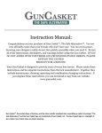
3-Ø11Elongated holes
120
Ø11
150
English
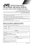
UNIT DIMENSIONS All dimensions below are given in mm.
200
240
454
402
436
396
72
15˚
377.5
318.5
5˚
5˚
114.5
223
15˚
These specifications are subject to change without notice.
4
English
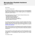
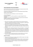
NAMES OF PARTS
Tilt adjustment screw
Tilt adjustment screw
Tilt fulcrum (pivot) screw
Ceiling mount
The same screws are also used on the opposite side.
Vertical/horizontal adjustment screws
The same screws are also used on the opposite side.
Vertical angle adjustment screws
Pin
L-plate
Horizontal angle
adjustment bolts. Use the
hex wrench provided.
5
English
INSTALLATION
Special techniques are necessary for safe installation. The customer should never perform
the installation work.
Consult your dealer concerning installation.
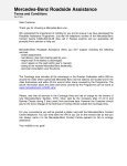
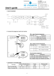
Projection Distance and Screen Size
● This projector uses a 1.5X zoom lens; therefore, the maximum projected image size is 1.5 times larger than the minimum
projected image size.
● Focus is possible at projection distances of from 2.5m to 20m. Use the distances shown below for reference.
Screen size (type)
min. - Max. (zoom)
Distance from the front screw
of the ceiling mount to the screen: L (m)
41.4 ~ 61.9
170 ~253.9
341.5 ~509.8
2.5
10
20
● If the edges of images are distorted when projecting at the minimum project distance, it is recommended that the projector be
moved slightly backward.
● Install the projector in a stable location away from walls and furniture for safety during light source lamp and filter
replacement.
350mm
Example: 317.5mm
Wall,
furniture,
etc.
300mm
The center-lines of the
projector lens and the ceiling
mount are not aligned.
Wall, furniture, etc.
500mm
L
Screen
172mm
90˚
72mm
200mm
Wall, furniture, etc.
CAUTION
●
·
·
·
·
Do not install in locations such as those shown below since this could result in malfunction or fire.
Box or other closed space where ventilation is not possible.
Places where there is oil smoke, water vapor or tobacco smoke.
Humid or dusty places.
Places where the temperature is low or high and the humidity is outside the permissible operating range.
Permissible temperature range: 5 - 35 degrees C
Permissible humidity range
:20% - 80% (no condensation)
● Direct sunlight and indoor lighting can cause the screen to appear whitish and difficult to view. Use curtains to
shut out light when necessary.
● Install the projector as level as possible; otherwise, malfunction may occur.
6
English
PARTS LIST
● The following parts are provided as accessories with this projector. Make sure all of the parts are present before stating the
installation work.
1. Ceiling mount
1
2. Drop prevention fixture
2
3. Hex wrench
1
4. Hex bolt
1
5. Flat washer
1
6. Spring washer
1
1
8. Flat washer
1
9. Spring washer
1
(M5 ✕ 8mm)
7. Screw
(M8 ✕ 15mm)
Completion drawing
7
English
HOW TO INSTALL
CAUTION
Do not connect the power plug to a power outlet until all preparations have been
completed.
1 Extend the two legs of the DLA-G10U/E by rotating.
Rotate until rotation becomes stiff and then stop to prevent damage. The other legs of
the projector do not rotate. Peel off the rubber pad adhered to one of the legs so the
embedded nut is visible.
Prepare the following tool
Screwdriver
Rubber pad
Leg
2 Remove the 4 adjustment screws and remove the ceiling mount. Remove the 2
screws from the ceiling mount and open the mount 90 degrees. Remove 2 screws
and then detach the stopper from the front of the mount.
Ceiling mount
Top fitting
Stopper
Vertical adjustment screw
Hinge
CAUTION
8
Use care to prevent the top fitting from dropping during the installation work since this
could result in injury or damage.
English
HOW TO INSTALL
3 Install the ceiling mount on the DLA-G10U/E by aligning the holes and cutouts, then install the stopper.
Top fitting
M5~8
½b
CAUTION
M5~8{g
Use care to prevent the top fitting from dropping
½in
bV
during the installation work since this could result
injury or damage.
Stopper
4 Firmly tighten the accessory screw (M8 ✕ 15mm) and the two DLA-G10U/E legs.
Prepare the following accessories
Spring washer (1)
Screw (M8 ✕ 15mm)
M8 ✕ 15mm (1)
Flat washer (1)
Spring washer
Flat washer
Completion drawing
9
[
M5~8{g
Xv
ObV
[
HOW TO PREVENT DROPPING
VäÖ
English
½bV
[
ºh
~
à
ï
1 Remove the U-fitting mounting screws.
U-fitting
2 Attach a drop prevention chain or wire to the U-fitting and fasten firmly with a screw.
Procure a drop
prevention chain or
wire of sufficient
strength.
If a chain is attached
3 Mount the drop prevention fixture on the ceiling mount.
Flat washer
Prepare the following accessories
M5 ✕ 8 bolt (1)
M5 ✕ 8 bolt
Spring washer
To ceiling
Drop prevention
fixture
Hex wrench
Spring washer (1)
Flat washer (1)
Drop prevention fixture (1)
4 Attach the drop prevention fixture to the ceiling using the same procedure as described in items 1 - 3.
[ Typical Installation ]
In case of a wood ceiling
Ceiling
Anchor (M5)
Mounting plate
Use materials that
will withstand the
weight of the
projector and the
ceiling mount.
Beam
Mounting bolt (M5)
To ceiling mount
1 Drill a hole through the mounting plate, beam
and ceiling.
2 Pass the mounting bolt (M5) through the hole
and fasten the drop prevention fixture.
CAUTION
10
In the case of a concrete ceiling
The M5 bolts for
ceiling mounting
are to be procured
separately. Consult
your dealer.
Mounting bolt (M5)
To ceiling mount
1 Drill a hole in the ceiling and then drive in the
anchor (M5).
2 Securely fasten the drop prevention fixture
with mounting bolts (M5).
Be sure to mount the drop prevention fixture directly above the projector. Consult your
dealer concerning the ceiling installation work.
English
INSTALLING THE CEILING MOUNT ON THE CEILING
Install the ceiling mount on the ceiling.
To ensure safety, special techniques are required for installation. Do not attempt to perform the installation work
yourself.
200
120
Mounting bolt
(M10 ✕ 4, procure separately)
The M10 bolts for
ceiling installation
are to be procured
separately. Consult
your dealer.
Ceiling mount
Consult your dealer concerning
installation. This company
assumes absolutely no
responsibility if the projector
drops due to insufficient
installation strength.
● Temporarily fasten with four M10 bolts in the sequence of
, , and
position
accurately and then securely tighten the four M10 bolts.
● The total weight of the projector and ceiling mount is 20.5kg.
● Install at a sufficient distance, referring to the projection distance range table on
page 6.
[ Typical Installation ]
In case of a wood ceiling
Ceiling
In the case of a concrete ceiling
Anchor
(M10)
Mounting plate
Use materials that
will withstand the
weight of the
projector and the
ceiling mount.
Beam
Mounting bolt (M10)
To ceiling mount
1 Drill holes of the above size in the ceiling and
mounting plate.
2 Drill holes in the beam.
3 Insert the mounting bolts (M10) through the
holes and fasten the ceiling mount. Make sure
the weight is supported by the beam. Reinforce
the beam if its strength is insufficient.
Mounting bolt (M10)
To ceiling mount
1 Drill holes of the above size in the ceiling and
then drive in the anchor (M10).
2 Securely fasten the ceiling mount with a
mounting bolt (M10). Use anchors that will
support the weight of the projector and ceiling
mount.
11
English
MOUNTING THE PROJECTOR ON THE CEILING MOUNT
1 Engage the L-plate on the pin of the ceiling mount.
Ceiling mount
Drop prevention fixture
L-plate
Pin
2 Fasten temporarily with the vertical angle adjustment screws (4) which were removed. After fastening with the vertical
adjustment angle screws (4), perform the adjustments described on page 13.
Vertical angle
adjustment screw
M5 ✕ 15 screws (4)
Prepare the following tool
Screwdriver
Completion drawing
Accessories to remove from
the projector
M5 ✕ 15 screws
(4)
12
English
PROJECTION ANGLE ADJUSTMENTS
Pre-adjustment Operations
· Look at the projector instruction manual and turn on the power.
· Use the zoom lens to match the projected image size to the size of the screen.
Perform the above operations before starting the projection angle adjustments.
Horizontal angle adjustment (top view)
1 Use the accessory hex wrench to loosen 6
bolts.
2 Move the projector left and right to center the
projected image horizontally on the screen.
3 When the angle has been correctly adjusted,
fasten the projector securely by tightening the
bolts.
7˚
7˚
Vertical angle adjustment (side view)
4 Center the projected image on the screen
vertically and then fasten the projector
securely by tightening the bolts.
15˚
15˚
Tilt angle adjustment (rear view)
5˚
5˚
5 Use the tilt adjustment screws (4 locations: 2
in front and 2 at the rear) to adjust the
projector so that the projected image is not
tilted in relation to the screen, then securely
tighten the screws.
Repeat the above adjustments if the
projected image is still unsatisfactory.
13
English
REPLACING THE LAMP AND FILTER
CAUTION
Observe the following cautions when replacing the light source lamp or filter. Failure to
do so can result in personal injury or projector damage.
· Turn off the POWER button of the remote control or OPERATE button of the projector
and disconnect the power cord from the power outlet.
· Take precautions to keep the DLG-G10U/E main unit and lens away from furniture,
lamps, etc.
· Prepare a stable place to stand where you can work comfortably. When the
installation work is difficult, lower to a safe height and call a professional installer.
1 To replace the lamp and filter, remove 2 screws while supporting the DLA-G10U/E with the hands and then lower it gently.
When removing the screws, always insert
the accessory hex wrench to prevent the
projector dropping suddenly.
2 Replace the lamp and filter. (Replace in accordance with the instructions given in the DLA-G10U/E instruction manual.)
Filter
Lamp
14
Part name
Model
Application
Applicable projector
Vertical tilt range
Horizontal tilt range
Horizontal pan range
Fixture Mass
Fixture size
Mass with projector mounted
External dimensions with projector mounted
Accessories
:
:
:
:
:
:
:
:
:
:
:
:
English
SPECIFICATIONS
Ceiling mount
EF-G10CG
Ceiling mounting the DLA-G10U/E projector
DLA-G10U/E only
+/-15 degrees
+/-5 degrees
+/-7 degrees
6.2kN
454mm (W) ✕ 359mm (D) ✕ 176mm (H)
20.5kN
454mm (W) ✕ 402mm (D) ✕ 377.5mm (H)
M8 ✕ 15 screw (1), flat washer (1)
Spring washer (1)
M5 ✕ 8 hex bolt (1), flat washer (1)
Spring washer (1)
Drop prevention fixture (2)
Hex wrench (1)
Instruction manual (1)
Service network (1)
· The specifications and appearance of this product are subject to change without notice.
15