1
IDP Series Intrusion Detection and Prevention Appliances
IDP250 Installation Guide
Release 5.0
Juniper Networks, Inc.
1194 North Mathilda Avenue
Sunnyvale, California 94089
USA
408-745-2000
www.juniper.net
Part Number: 530-029729-01, Revision 01
This product includes the Envoy SNMP Engine, developed by Epilogue Technology, an Integrated Systems Company. Copyright © 1986-1997, Epilogue
Technology Corporation. All rights reserved. This program and its documentation were developed at private expense, and no part of them is in the public
domain.
This product includes memory allocation software developed by Mark Moraes, copyright © 1988, 1989, 1993, University of Toronto.
This product includes FreeBSD software developed by the University of California, Berkeley, and its contributors. All of the documentation and software
included in the 4.4BSD and 4.4BSD-Lite Releases is copyrighted by the Regents of the University of California. Copyright © 1979, 1980, 1983, 1986, 1988,
1989, 1991, 1992, 1993, 1994. The Regents of the University of California. All rights reserved.
GateD software copyright © 1995, the Regents of the University. All rights reserved. Gate Daemon was originated and developed through release 3.0 by
Cornell University and its collaborators. Gated is based on Kirton’s EGP, UC Berkeley’s routing daemon (routed), and DCN’s HELLO routing protocol.
Development of Gated has been supported in part by the National Science Foundation. Portions of the GateD software copyright © 1988, Regents of the
University of California. All rights reserved. Portions of the GateD software copyright © 1991, D. L. S. Associates.
This product includes software developed by Maker Communications, Inc., copyright © 1996, 1997, Maker Communications, Inc.
Juniper Networks, the Juniper Networks logo, JUNOS, NetScreen, ScreenOS, and Steel-Belted Radius are registered trademarks of Juniper Networks, Inc. in
the United States and other countries. JUNOSe is a trademark of Juniper Networks, Inc. All other trademarks, service marks, registered trademarks, or
registered service marks are the property of their respective owners.
Juniper Networks assumes no responsibility for any inaccuracies in this document. Juniper Networks reserves the right to change, modify, transfer, or
otherwise revise this publication without notice.
Products made or sold by Juniper Networks or components thereof might be covered by one or more of the following patents that are owned by or licensed
to Juniper Networks: U.S. Patent Nos. 5,473,599, 5,905,725, 5,909,440, 6,192,051, 6,333,650, 6,359,479, 6,406,312, 6,429,706, 6,459,579, 6,493,347,
6,538,518, 6,538,899, 6,552,918, 6,567,902, 6,578,186, and 6,590,785.
IDP Series Intrusion Detection and Prevention Appliances IDP250 Installation Guide
Copyright © 2009, Juniper Networks, Inc.
All rights reserved. Printed in USA.
Revision History
May 2009—
The information in this document is current as of the date listed in the revision history.
ii
■
END USER LICENSE AGREEMENT
READ THIS END USER LICENSE AGREEMENT (“AGREEMENT”) BEFORE DOWNLOADING, INSTALLING, OR USING THE SOFTWARE. BY DOWNLOADING,
INSTALLING, OR USING THE SOFTWARE OR OTHERWISE EXPRESSING YOUR AGREEMENT TO THE TERMS CONTAINED HEREIN, YOU (AS CUSTOMER
OR IF YOU ARE NOT THE CUSTOMER, AS A REPRESENTATIVE/AGENT AUTHORIZED TO BIND THE CUSTOMER) CONSENT TO BE BOUND BY THIS
AGREEMENT. IF YOU DO NOT OR CANNOT AGREE TO THE TERMS CONTAINED HEREIN, THEN (A) DO NOT DOWNLOAD, INSTALL, OR USE THE SOFTWARE,
AND (B) YOU MAY CONTACT JUNIPER NETWORKS REGARDING LICENSE TERMS.
1. The Parties. The parties to this Agreement are (i) Juniper Networks, Inc. (if the Customer’s principal office is located in the Americas) or Juniper Networks
(Cayman) Limited (if the Customer’s principal office is located outside the Americas) (such applicable entity being referred to herein as “Juniper”), and (ii)
the person or organization that originally purchased from Juniper or an authorized Juniper reseller the applicable license(s) for use of the Software (“Customer”)
(collectively, the “Parties”).
2. The Software. In this Agreement, “Software” means the program modules and features of the Juniper or Juniper-supplied software, for which Customer
has paid the applicable license or support fees to Juniper or an authorized Juniper reseller, or which was embedded by Juniper in equipment which Customer
purchased from Juniper or an authorized Juniper reseller. “Software” also includes updates, upgrades and new releases of such software. “Embedded
Software” means Software which Juniper has embedded in or loaded onto the Juniper equipment and any updates, upgrades, additions or replacements
which are subsequently embedded in or loaded onto the equipment.
3. License Grant. Subject to payment of the applicable fees and the limitations and restrictions set forth herein, Juniper grants to Customer a non-exclusive
and non-transferable license, without right to sublicense, to use the Software, in executable form only, subject to the following use restrictions:
a. Customer shall use Embedded Software solely as embedded in, and for execution on, Juniper equipment originally purchased by Customer from Juniper
or an authorized Juniper reseller.
b. Customer shall use the Software on a single hardware chassis having a single processing unit, or as many chassis or processing units for which Customer
has paid the applicable license fees; provided, however, with respect to the Steel-Belted Radius or Odyssey Access Client software only, Customer shall use
such Software on a single computer containing a single physical random access memory space and containing any number of processors. Use of the
Steel-Belted Radius or IMS AAA software on multiple computers or virtual machines (e.g., Solaris zones) requires multiple licenses, regardless of whether
such computers or virtualizations are physically contained on a single chassis.
c. Product purchase documents, paper or electronic user documentation, and/or the particular licenses purchased by Customer may specify limits to
Customer’s use of the Software. Such limits may restrict use to a maximum number of seats, registered endpoints, concurrent users, sessions, calls,
connections, subscribers, clusters, nodes, realms, devices, links, ports or transactions, or require the purchase of separate licenses to use particular features,
functionalities, services, applications, operations, or capabilities, or provide throughput, performance, configuration, bandwidth, interface, processing,
temporal, or geographical limits. In addition, such limits may restrict the use of the Software to managing certain kinds of networks or require the Software
to be used only in conjunction with other specific Software. Customer’s use of the Software shall be subject to all such limitations and purchase of all applicable
licenses.
d. For any trial copy of the Software, Customer’s right to use the Software expires 30 days after download, installation or use of the Software. Customer
may operate the Software after the 30-day trial period only if Customer pays for a license to do so. Customer may not extend or create an additional trial
period by re-installing the Software after the 30-day trial period.
e. The Global Enterprise Edition of the Steel-Belted Radius software may be used by Customer only to manage access to Customer’s enterprise network.
Specifically, service provider customers are expressly prohibited from using the Global Enterprise Edition of the Steel-Belted Radius software to support any
commercial network access services.
The foregoing license is not transferable or assignable by Customer. No license is granted herein to any user who did not originally purchase the applicable
license(s) for the Software from Juniper or an authorized Juniper reseller.
4. Use Prohibitions. Notwithstanding the foregoing, the license provided herein does not permit the Customer to, and Customer agrees not to and shall
not: (a) modify, unbundle, reverse engineer, or create derivative works based on the Software; (b) make unauthorized copies of the Software (except as
necessary for backup purposes); (c) rent, sell, transfer, or grant any rights in and to any copy of the Software, in any form, to any third party; (d) remove
any proprietary notices, labels, or marks on or in any copy of the Software or any product in which the Software is embedded; (e) distribute any copy of
the Software to any third party, including as may be embedded in Juniper equipment sold in the secondhand market; (f) use any ‘locked’ or key-restricted
feature, function, service, application, operation, or capability without first purchasing the applicable license(s) and obtaining a valid key from Juniper, even
if such feature, function, service, application, operation, or capability is enabled without a key; (g) distribute any key for the Software provided by Juniper
to any third party; (h) use the Software in any manner that extends or is broader than the uses purchased by Customer from Juniper or an authorized Juniper
reseller; (i) use Embedded Software on non-Juniper equipment; (j) use Embedded Software (or make it available for use) on Juniper equipment that the
Customer did not originally purchase from Juniper or an authorized Juniper reseller; (k) disclose the results of testing or benchmarking of the Software to
any third party without the prior written consent of Juniper; or (l) use the Software in any manner other than as expressly provided herein.
5. Audit. Customer shall maintain accurate records as necessary to verify compliance with this Agreement. Upon request by Juniper, Customer shall furnish
such records to Juniper and certify its compliance with this Agreement.
■
iii
6. Confidentiality. The Parties agree that aspects of the Software and associated documentation are the confidential property of Juniper. As such, Customer
shall exercise all reasonable commercial efforts to maintain the Software and associated documentation in confidence, which at a minimum includes
restricting access to the Software to Customer employees and contractors having a need to use the Software for Customer’s internal business purposes.
7. Ownership. Juniper and Juniper’s licensors, respectively, retain ownership of all right, title, and interest (including copyright) in and to the Software,
associated documentation, and all copies of the Software. Nothing in this Agreement constitutes a transfer or conveyance of any right, title, or interest in
the Software or associated documentation, or a sale of the Software, associated documentation, or copies of the Software.
8. Warranty, Limitation of Liability, Disclaimer of Warranty. The warranty applicable to the Software shall be as set forth in the warranty statement that
accompanies the Software (the “Warranty Statement”). Nothing in this Agreement shall give rise to any obligation to support the Software. Support services
may be purchased separately. Any such support shall be governed by a separate, written support services agreement. TO THE MAXIMUM EXTENT PERMITTED
BY LAW, JUNIPER SHALL NOT BE LIABLE FOR ANY LOST PROFITS, LOSS OF DATA, OR COSTS OR PROCUREMENT OF SUBSTITUTE GOODS OR SERVICES,
OR FOR ANY SPECIAL, INDIRECT, OR CONSEQUENTIAL DAMAGES ARISING OUT OF THIS AGREEMENT, THE SOFTWARE, OR ANY JUNIPER OR
JUNIPER-SUPPLIED SOFTWARE. IN NO EVENT SHALL JUNIPER BE LIABLE FOR DAMAGES ARISING FROM UNAUTHORIZED OR IMPROPER USE OF ANY
JUNIPER OR JUNIPER-SUPPLIED SOFTWARE. EXCEPT AS EXPRESSLY PROVIDED IN THE WARRANTY STATEMENT TO THE EXTENT PERMITTED BY LAW,
JUNIPER DISCLAIMS ANY AND ALL WARRANTIES IN AND TO THE SOFTWARE (WHETHER EXPRESS, IMPLIED, STATUTORY, OR OTHERWISE), INCLUDING
ANY IMPLIED WARRANTY OF MERCHANTABILITY, FITNESS FOR A PARTICULAR PURPOSE, OR NONINFRINGEMENT. IN NO EVENT DOES JUNIPER
WARRANT THAT THE SOFTWARE, OR ANY EQUIPMENT OR NETWORK RUNNING THE SOFTWARE, WILL OPERATE WITHOUT ERROR OR INTERRUPTION,
OR WILL BE FREE OF VULNERABILITY TO INTRUSION OR ATTACK. In no event shall Juniper’s or its suppliers’ or licensors’ liability to Customer, whether
in contract, tort (including negligence), breach of warranty, or otherwise, exceed the price paid by Customer for the Software that gave rise to the claim, or
if the Software is embedded in another Juniper product, the price paid by Customer for such other product. Customer acknowledges and agrees that Juniper
has set its prices and entered into this Agreement in reliance upon the disclaimers of warranty and the limitations of liability set forth herein, that the same
reflect an allocation of risk between the Parties (including the risk that a contract remedy may fail of its essential purpose and cause consequential loss),
and that the same form an essential basis of the bargain between the Parties.
9. Termination. Any breach of this Agreement or failure by Customer to pay any applicable fees due shall result in automatic termination of the license
granted herein. Upon such termination, Customer shall destroy or return to Juniper all copies of the Software and related documentation in Customer’s
possession or control.
10. Taxes. All license fees payable under this agreement are exclusive of tax. Customer shall be responsible for paying Taxes arising from the purchase of
the license, or importation or use of the Software. If applicable, valid exemption documentation for each taxing jurisdiction shall be provided to Juniper prior
to invoicing, and Customer shall promptly notify Juniper if their exemption is revoked or modified. All payments made by Customer shall be net of any
applicable withholding tax. Customer will provide reasonable assistance to Juniper in connection with such withholding taxes by promptly: providing Juniper
with valid tax receipts and other required documentation showing Customer’s payment of any withholding taxes; completing appropriate applications that
would reduce the amount of withholding tax to be paid; and notifying and assisting Juniper in any audit or tax proceeding related to transactions hereunder.
Customer shall comply with all applicable tax laws and regulations, and Customer will promptly pay or reimburse Juniper for all costs and damages related
to any liability incurred by Juniper as a result of Customer’s non-compliance or delay with its responsibilities herein. Customer’s obligations under this
Section shall survive termination or expiration of this Agreement.
11. Export. Customer agrees to comply with all applicable export laws and restrictions and regulations of any United States and any applicable foreign
agency or authority, and not to export or re-export the Software or any direct product thereof in violation of any such restrictions, laws or regulations, or
without all necessary approvals. Customer shall be liable for any such violations. The version of the Software supplied to Customer may contain encryption
or other capabilities restricting Customer’s ability to export the Software without an export license.
12. Commercial Computer Software. The Software is “commercial computer software” and is provided with restricted rights. Use, duplication, or disclosure
by the United States government is subject to restrictions set forth in this Agreement and as provided in DFARS 227.7201 through 227.7202-4, FAR 12.212,
FAR 27.405(b)(2), FAR 52.227-19, or FAR 52.227-14(ALT III) as applicable.
13. Interface Information. To the extent required by applicable law, and at Customer's written request, Juniper shall provide Customer with the interface
information needed to achieve interoperability between the Software and another independently created program, on payment of applicable fee, if any.
Customer shall observe strict obligations of confidentiality with respect to such information and shall use such information in compliance with any applicable
terms and conditions upon which Juniper makes such information available.
14. Third Party Software. Any licensor of Juniper whose software is embedded in the Software and any supplier of Juniper whose products or technology
are embedded in (or services are accessed by) the Software shall be a third party beneficiary with respect to this Agreement, and such licensor or vendor
shall have the right to enforce this Agreement in its own name as if it were Juniper. In addition, certain third party software may be provided with the
Software and is subject to the accompanying license(s), if any, of its respective owner(s). To the extent portions of the Software are distributed under and
subject to open source licenses obligating Juniper to make the source code for such portions publicly available (such as the GNU General Public License
(“GPL”) or the GNU Library General Public License (“LGPL”)), Juniper will make such source code portions (including Juniper modifications, as appropriate)
available upon request for a period of up to three years from the date of distribution. Such request can be made in writing to Juniper Networks, Inc., 1194
N. Mathilda Ave., Sunnyvale, CA 94089, ATTN: General Counsel. You may obtain a copy of the GPL at http://www.gnu.org/licenses/gpl.html, and
a copy of the LGPL at http://www.gnu.org/licenses/lgpl.html.
15. Miscellaneous. This Agreement shall be governed by the laws of the State of California without reference to its conflicts of laws principles. The provisions
of the U.N. Convention for the International Sale of Goods shall not apply to this Agreement. For any disputes arising under this Agreement, the Parties
hereby consent to the personal and exclusive jurisdiction of, and venue in, the state and federal courts within Santa Clara County, California. This Agreement
constitutes the entire and sole agreement between Juniper and the Customer with respect to the Software, and supersedes all prior and contemporaneous
iv
■
agreements relating to the Software, whether oral or written (including any inconsistent terms contained in a purchase order), except that the terms of a
separate written agreement executed by an authorized Juniper representative and Customer shall govern to the extent such terms are inconsistent or conflict
with terms contained herein. No modification to this Agreement nor any waiver of any rights hereunder shall be effective unless expressly assented to in
writing by the party to be charged. If any portion of this Agreement is held invalid, the Parties agree that such invalidity shall not affect the validity of the
remainder of this Agreement. This Agreement and associated documentation has been written in the English language, and the Parties agree that the English
version will govern. (For Canada: Les parties aux présentés confirment leur volonté que cette convention de même que tous les documents y compris tout
avis qui s'y rattaché, soient redigés en langue anglaise. (Translation: The parties confirm that this Agreement and all related documentation is and will be
in the English language)).
■
v
vi
■
Table of Contents
Preface
xi
Objectives ......................................................................................................xi
Audience ........................................................................................................xi
Documentation Conventions ..........................................................................xi
Related Documentation ................................................................................xiii
Requesting Technical Support .......................................................................xiv
Self-Help Online Tools and Resources ....................................................xiv
Opening a Case with JTAC .......................................................................xv
Part 1
Hardware and Software Overview
Chapter 1
Hardware Overview
3
IDP250 Overview ............................................................................................3
Power Supply ..................................................................................................4
Hard Drive ......................................................................................................4
Fans ................................................................................................................4
System Status LEDs .........................................................................................4
USB Port ..........................................................................................................5
Serial Console Port ..........................................................................................5
Management Interface Port .............................................................................5
High Availability Interface Port ........................................................................6
Traffic Interface Ports ......................................................................................7
Copper Ports .............................................................................................7
Fiber Ports ................................................................................................8
Traffic Interface Features ..........................................................................9
Deployment Mode ............................................................................10
Internal Bypass .................................................................................10
NICs Off ...........................................................................................11
External Bypass ................................................................................12
Peer Port Modulation ..............................................................................12
Layer 2 Bypass ........................................................................................13
Chapter 2
Software Overview
15
On-Box Software Overview ...........................................................................15
Centralized Management with NSM Overview ...............................................16
J-Security Center Updates Overview ..............................................................17
Table of Contents
■
vii
IDP250 Installation Guide
Part 2
Performing the Installation
Chapter 3
Installation Overview
21
Before You Begin ...........................................................................................21
Basic Steps ....................................................................................................22
Chapter 4
Installing the Appliance to Your Equipment Rack and Connecting
Power
23
Rack Mounting Kits and Required Tools ........................................................23
Mounting to Midmount Brackets ...................................................................24
Mounting to Rack Rails ..................................................................................25
Connecting Power .........................................................................................25
Chapter 5
Performing the Initial Network Configuration and Licensing
Tasks
27
Performing the Initial Configuration ..............................................................27
Getting Started with the EasyConfig Wizard (Serial Console Port) ..................29
Getting Started with the QuickStart Wizard (Management Port) ....................30
Getting Started with the ACM Wizard (Management Port) .............................31
Installing the Product License Key .................................................................32
Chapter 6
Connecting the IDP Traffic Interfaces to Your Network and Verifying
Traffic Flow
35
Guidelines for Connecting IDP Interfaces to Your Network Devices ...............35
Choosing Cables for Traffic Interfaces (Copper Ports) ....................................36
Connecting Devices That Support Auto-MDIX .........................................36
Connecting Devices That Do Not Support Auto-MDIX .............................37
Connecting Devices to Support Internal Bypass ......................................37
Connecting and Disconnecting Fiber Cables ..................................................37
Verifying Traffic Flow ....................................................................................38
Part 3
Adding the IDP Appliance to NSM
Chapter 7
Adding the IDP Appliance to NSM
41
Reviewing Compatibility with NSM ...............................................................41
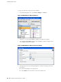
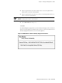
Adding a Reachable IDP Device to NSM ........................................................41
viii
■
Table of Contents
Table of Contents
Part 4
Upgrading Software and Installing Field Replaceable Units
Chapter 8
Upgrading Software
49
Updating Software (NSM Procedure) .............................................................49
Upgrading Software (CLI Procedure) ..............................................................51
Chapter 9
Installing Field Replaceable Units
53
Replacing a Power Supply .............................................................................53
Chapter 10
Reimaging the Appliance
55
Reimaging and Relicensing an Appliance ......................................................55
Part 5
Technical Specifications and Compliance Statements
Chapter 11
Technical Specifications
59
IDP250 Technical Specifications ....................................................................59
Chapter 12
Compliance Statements
61
Standards Compliance ...................................................................................61
Chapter 13
Common Criteria EAL2 Compliance
63
Common Criteria EAL2 Compliance ..............................................................63
Part 6
Index
Index .............................................................................................................67
Table of Contents
■
ix
IDP250 Installation Guide
x
■
Table of Contents
Preface
This preface includes the following topics:
■
Objectives on page xi
■
Audience on page xi
■
Documentation Conventions on page xi
■
Related Documentation on page xiii
■
Requesting Technical Support on page xiv
Objectives
This guide explains how to install, configure, update, and service an IDP Series
Intrusion Detection and Prevention appliance.
Audience
This guide is intended for experienced system and network specialists.
Documentation Conventions
This section provides all the documentation conventions that are followed in this
guide. Table 1 on page xi defines notice icons used in this guide.
Table 1: Notice Icons
Icon
Meaning
Description
Informational note
Indicates important features or instructions.
Caution
Indicates a situation that might result in loss of data or hardware damage.
Warning
Alerts you to the risk of personal injury or death.
Laser warning
Alerts you to the risk of personal injury from a laser.
Objectives
■
xi
IDP250 Installation Guide
Table 2 on page xii defines text conventions used in this guide.
Table 2: Text Conventions
Convention
Description
Bold typeface like this
■
Represents commands and keywords
in text.
■
Represents keywords
■
Represents UI elements
Examples
■
Issue the clock source command.
■
Specify the keyword exp-msg.
■
Click User Objects
Bold typeface like this
Represents text that the user must type.
user input
fixed-width font
Represents information as displayed on
the terminal screen.
host1#
show ip ospf
Routing Process OSPF 2 with Router
ID 5.5.0.250
Router is an area Border Router
(ABR)
Key names linked with a plus (+)
sign
Indicates that you must press two or more
keys simultaneously.
Ctrl + d
Italics
■
Emphasizes words
■
Identifies variables
The angle bracket (>)
Indicates navigation paths through the UI
by clicking menu options and links.
■
The product supports two levels of
access, user and privileged.
■
clusterID, ipAddress.
Object Manager > User Objects > Local
Objects
Table 3 on page xii defines syntax conventions used in this guide.
Table 3: Syntax Conventions
Convention
Description
Examples
Words in plain text
Represent keywords
terminal length
Words in italics
Represent variables
mask, accessListName
Words separated by the pipe ( | )
symbol
Represent a choice to select one keyword or
variable to the left or right of this symbol. The
keyword or variable can be optional or
required.
diagnostic | line
Words enclosed in brackets ( [ ] )
Represent optional keywords or variables.
[ internal | external ]
Words enclosed in brackets followed
by and asterisk ( [ ]*)
Represent optional keywords or variables that
can be entered more than once.
[ level1 | level2 | 11 ]*
Words enclosed in braces ( { } )
Represent required keywords or variables.
{ permit | deny } { in | out } {
clusterId | ipAddress }
xii
■
Documentation Conventions
Preface
Related Documentation
Table 4 on page xiii lists related IDP documentation.
Table 4: Related IDP Documentation
Document
Description
Release notes
Contains information about what is included in a specific product release:
supported features, unsupported features, changed features, known problems,
and resolved problems. If the information in the release notes differs from
the information found in the documentation set, follow the release notes.
ACM Online Help
Available through the Appliance Configuration Manager (ACM). The
context-sensitive online help describes how to use the QuickStart and ACM
Wizard pages to configure network settings, network interfaces, and NIC
features.
■
IDP Series Installation Guide: IDP200,
IDP600, IDP1100
■
IDP75 Installation Guide
■
IDP250 Installation Guide
■
IDP800 Installation Guide
■
IDP8200 Installation Guide
Provides instructions for installing, configuring, updating, and servicing the
IDP Series appliances.
IDP Concepts and Examples Guide
Explains IDP features and provides examples of how to use the system.
IDP Administration Guide
Provides procedures for implementing IDP features, monitoring performance,
and monitoring security events.
IDP Custom Attack Objects Reference and
Examples Guide
Provides in-depth examples and reference information for creating custom
attack objects.
IDP Reporter User’s Guide
Describes how to use IDP Reporter to view and generate security reports and
application usage reports.
Table 4 on page xiii lists related NSM documentation.
Table 5: Related NSM Documentation
Document
Description
Network and Security Manager release notes
Provides information about new features, changed features, fixed problems,
and known issues with the NSM release.
Network and Security Manager Installation Guide
Describes how to install the NSM management system on a single server or
on separate servers. It also includes information on how to install and run
the NSM user interface. This guide is intended for IT administrators responsible
for the installation and/or upgrade to NSM.
Related Documentation
■
xiii
IDP250 Installation Guide
Table 5: Related NSM Documentation (continued)
Document
Description
Network and Security Manager Configuring
Intrusion Detection and Prevention Devices Guide
Describes how to configure and manage IDP devices using NSM. This guide
also helps in understanding of how to configure basic and advanced NSM
functionality, including adding new devices, deploying new device
configurations, updating device firmware, viewing log information, and
monitoring the status of IDP devices.
Network and Security Manager Administration
Guide
Describes how to use and configure key management features in the NSM.
It provides conceptual information, suggested workflows, and examples where
applicable. This guide is best used in conjunction with the NSM Online Help,
which provides step-by-step instructions for performing management tasks
in the NSM UI.
This guide is intended for application administrators or those individuals
responsible for owning the server and security infrastructure and configuring
the product for multi-user systems. It is also intended for device configuration
administrators, firewall and VPN administrators, and network security
operation center administrators.
Network and Security Manager Online Help
Provides task-oriented procedures describing how to perform basic tasks in
the NSM user interface. It also includes a brief overview of the NSM system
and a description of the GUI elements.
Requesting Technical Support
Technical product support is available through the Juniper Networks Technical
Assistance Center (JTAC). If you are a customer with an active J-Care or JNASC support
contract, or are covered under warranty, and need post-sales technical support, you
can access our tools and resources online or open a case with JTAC.
■
JTAC policies—For a complete understanding of our JTAC procedures and policies,
review the JTAC User Guide located at
http://www.juniper.net/customers/support/downloads/710059.pdf.
■
Product warranties—For product warranty information, visit
http://www.juniper.net/support/warranty/.
■
JTAC Hours of Operation —The JTAC centers have resources available 24 hours
a day, 7 days a week, 365 days a year.
Self-Help Online Tools and Resources
For quick and easy problem resolution, Juniper Networks has designed an online
self-service portal called the Customer Support Center (CSC) that provides you with
the following features:
xiv
■
■
Find CSC offerings: http://www.juniper.net/customers/support/
■
Search for known bugs: http://www2.juniper.net/kb/
■
Find product documentation: http://www.juniper.net/techpubs/
Requesting Technical Support
Preface
■
Find solutions and answer questions using our Knowledge Base:
http://kb.juniper.net/
■
Download the latest versions of software and review release notes:
http://www.juniper.net/customers/csc/software/
■
Search technical bulletins for relevant hardware and software notifications:
https://www.juniper.net/alerts/
■
Join and participate in the Juniper Networks Community Forum:
http://www.juniper.net/company/communities/
■
Open a case online in the CSC Case Management tool: http://www.juniper.net/cm/
To verify service entitlement by product serial number, use our Serial Number
Entitlement (SNE) Tool located at https://tools.juniper.net/SerialNumberEntitlementSearch/.
Opening a Case with JTAC
You can open a case with JTAC on the Web or by telephone.
■
Use the Case Management tool in the CSC at http://www.juniper.net/cm/ .
■
Call 1-888-314-JTAC (1-888-314-5822 toll-free in the USA, Canada, and Mexico).
For international or direct-dial options in countries without toll-free numbers, see
http://www.juniper.net/support/requesting support.html
Requesting Technical Support
■
xv
IDP250 Installation Guide
xvi
■
Requesting Technical Support
Part 1
Hardware and Software Overview
■
Hardware Overview on page 3
■
Software Overview on page 15
Hardware and Software Overview
■
1
IDP250 Installation Guide
2
■
Hardware and Software Overview
Chapter 1
Hardware Overview
This chapter includes the following topics:
■
IDP250 Overview on page 3
■
Power Supply on page 4
■
Hard Drive on page 4
■
Fans on page 4
■
System Status LEDs on page 4
■
USB Port on page 5
■
Serial Console Port on page 5
■
Management Interface Port on page 5
■
High Availability Interface Port on page 6
■
Traffic Interface Ports on page 7
IDP250 Overview
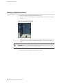
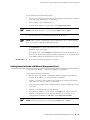
The IDP250 appliance is optimal for medium central sites or large branch offices.
Figure 1 on page 3 shows the location of appliance LEDs and ports.
Figure 1: IDP250 Front Panel
Related Topics
■
System Status LEDs on page 4
■
USB Port on page 5
■
Serial Console Port on page 5
■
Management Interface Port on page 5
■
High Availability Interface Port on page 6
IDP250 Overview
■
3
IDP250 Installation Guide
■
Traffic Interface Ports on page 7
■
IDP250 Technical Specifications on page 59
Power Supply
The appliance has one power supply. It is a field replaceable unit (FRU).
Related Topics
Replacing a Power Supply on page 53
■
Hard Drive
The appliance has one 80 GB hard drive. It is not a field replaceable unit (FRU).
Fans
When the system is cool, appliance fans spin at a slower speed to reduce noise and
save energy. As the system heats up, the fans run at a faster speed. In the event of
fan failure, the appliance fault LED blinks and the remaining fan or fans run at full
speed until the failed fan is replaced.
The fans for this model are not field replaceable units (FRUs).
System Status LEDs
Table 6 on page 4 describes system status LED states.
Table 6: System Status LED States
LED
Status
Description
Power
Solid green
System is powered on.
Off
System is powered off.
Flashing amber
Hard disk is active.
Off
Hard drive has no activity.
Slowly blinking red
Power failure.
Quickly blinking red
Fan failure.
Solid red
Overheating.
Off
Heat and power are normal.
Hard Drives
Fault
4
■
Power Supply
Chapter 1: Hardware Overview
USB Port
The appliance has a USB port you can use to reimage the appliance, if necessary.
Serial Console Port
The console serial port provides access, using an RJ-45 connector, to the
command-line interface (CLI).
NOTE: Although both the console serial port and the management port use RJ-45
connectors, do not plug the network cable into the console serial port.
Management Interface Port
The management interface port is a 10/100/1000 Mbps Ethernet port. In the
configuration and logs, the port is eth0. Use this port as a dedicated management
port, connecting the device to a switch accessible by your management subnet.
The IP address you assign the management port is the IP address you use to connect
to the Appliance Configuration Manager (ACM) when you initially configure the device.
It is also the address the Network and Security Manager (NSM) uses to connect to
the device.
Figure 2 on page 5 shows the management interface port LEDs.
Figure 2: Management Interface Port LEDs
Table 7 on page 5 describes the management interface port LED states.
Table 7: Management Port LEDs
LED
State
Description
LINK
Glows green
Link is present.
Blinks green
Activity.
Off
No link is present.
USB Port
■
5
IDP250 Installation Guide
Table 7: Management Port LEDs (continued)
LED
State
Description
TX/RX
Orange
Connection is 1000 Mbps.
Green
Connection is 100 Mbps.
Off
If LINK indicates activity, TX/RX off indicates connection
is 10 Mbps.
If LINK indicates no activity, TX/RX off indicates no activity
as well.
High Availability Interface Port
The high availability interface port is a 10/100/1000 Mbps Ethernet port. In the
configuration and logs, the port is eth1. The high availability interface is a dedicated
interface used to share state information among IDP appliances in a high availability
cluster.
NOTE: IDP 5.0 does not support high availability.
Figure 3 on page 6 shows the management interface port LEDs.
Figure 3: High Availability Interface Port LEDs
Table 8 on page 6 describes the high availability interface port LED states.
Table 8: High Availability Port LEDs
6
■
LED
State
Description
LINK
Glows green
Link is present.
Blinks green
Activity.
Off
No link is present.
High Availability Interface Port
Chapter 1: Hardware Overview
Table 8: High Availability Port LEDs (continued)
LED
State
Description
TX/RX
Orange
Connection is 1000 Mbps.
Green
Connection is 100 Mbps.
Off
If LINK indicates activity, TX/RX off indicates connection
is 10 Mbps.
If LINK indicates no activity, TX/RX off indicates no activity
as well.
Traffic Interface Ports
You use the traffic interface ports to connect the appliance to your network. The
interfaces receive and forward traffic. The type and capacity of interface ports vary
by model.
The following topics describe features of traffic interface ports:
■
Copper Ports on page 7
■
Fiber Ports on page 8
■
Traffic Interface Features on page 9
■
Peer Port Modulation on page 12
■
Layer 2 Bypass on page 13
Copper Ports
Figure 4 on page 7 shows copper port LEDs.
Figure 4: Copper Port LEDs
Table 9 on page 8 describes copper port LED states.
Traffic Interface Ports
■
7
IDP250 Installation Guide
Table 9: Copper Port LEDs
LED
State
Description
LINK ACT
Glows green
Link is present.
Blinks green
Activity.
Off
No link present.
Green
Connection is 100 Mbps.
Yellow
Connection is 1 Gbps.
Off
If LINK ACT is on, the connection is 10 Mbps. If LINK ACT
is off, LINK SPD off indicates no link is present as well.
Green
Interface is not in bypass mode.
Yellow
Interface is in bypass mode.
Off
Interface is turned off (NICs off state).
LINK SPD
BYP
NOTE: For copper interface ports, if failure or shutdown triggers NICs off state, LINK
ACT and LINK SPD LEDs are turned off.
Fiber Ports
Figure 5 on page 8 shows fiber port LEDs.
Figure 5: Fiber Port LEDs
Table 10 on page 9 describes fiber port LED states.
8
■
Traffic Interface Ports
Chapter 1: Hardware Overview
Table 10: Fiber Port LEDs
LED
State
Description
LINK ACT
Glows green
Link is present.
Flashes green
Activity.
Off
No link present.
Green
Connection is 100 Mbps.
Yellow
Connection is 1 Gbps.
Orange
Connection is 10 Gbps.
Off
If LINK ACT is on, the connection is 10 Mbps. If LINK ACT
is off, LINK SPD off indicates no link is present as well.
Green
Interface is not in bypass mode.
Yellow
Interface is in bypass mode.
Off
Interface is turned off (NICs off state).
LINK SPD
BYP
NOTE: For fiber interface ports, if failure or shutdown triggers NICs off state, LINK
ACT and LINK SPD LEDs remain lit.
Traffic Interface Features
In IDP deployments, pairs of traffic interfaces are implemented as virtual routers.
For example, interface ports eth2 and eth3 form a virtual router vr1. For each virtual
router, you use the Appliance Configuration Manager (ACM) to configure the
deployment mode (sniffer or transparent) and bypass options (internal, external, or
off). The following topics describe these settings:
■
Deployment Mode on page 10
■
Internal Bypass on page 10
■
NICs Off on page 11
■
External Bypass on page 12
For guidance on using ACM to configure virtual router settings, see the ACM online
help.
Traffic Interface Ports
■
9
IDP250 Installation Guide
Deployment Mode
For each virtual router, you select the deployment mode:
■
Sniffer–In an out-of-path, sniffer mode deployment, the IDP appliance can detect
attacks but can take only limited action. You connect the IDP traffic interfaces
to a mirrored port of a network hub or switch.
■
Transparent–In an in-path, transparent mode deployment, traffic arrives in one
interface and is forwarded through the other. The IDP appliance detects attacks
and takes action according to your security policy rules. You connect the IDP
traffic interfaces to firewalls or switches in the network path.
You can deploy a mix of sniffer and transparent mode virtual routers on the same
IDP appliance.
For more information on deployment mode, see the IDP Concepts and Examples
Guide.
Internal Bypass
The Internal Bypass setting supports network security policies that privilege availability
over security. In the event of failure or graceful shutdown, with internal bypass
configured, the interfaces to enter an internal bypass state. In internal bypass, physical
interfaces join mechanically to form a circuit that bypasses IDP processing. For
example, if you configure internal bypass for vr0, and the IDP appliance encounters
failure or is shut down, eth2 and eth3 join to form a circuit that avoids the IDP engine
and forwards the traffic to the next network hop.
Internal bypass operates through a timing mechanism. When enabled, the timer on
traffic interfaces counts down to a bypass trigger point. When the IDP appliance is
turned on and available, it sends a reset signal to the traffic interface timer so that
it does not reach the bypass trigger point. If the IDP operating system encounters
failure, then it fails to send the reset signal, the timer counts down to the trigger
point, and the traffic interfaces enter a bypass state. If the IDP appliance is shut down
gracefully, the traffic interfaces immediately enter bypass.
Figure 6 on page 11 shows the communications path when a virtual router is in
internal bypass state.
10
■
Traffic Interface Ports
Chapter 1: Hardware Overview
Figure 6: Internal Bypass
When the IDP operating system resumes healthy operations, it sends a reset signal
to the traffic interfaces, and the interfaces resume normal operation.
NOTE: All copper port traffic interfaces support internal bypass. Some, but not all,
fiber port traffic interfaces support internal bypass. Check with your sales contact
for applicable part numbers.
NOTE: Bypass settings are applicable only for deployments where the virtual router
is in the network path—transparent mode deployments.
NOTE: The bypass and PPM features are applied independently. The Internal Bypass
setting is related to the status of the IDP operating system. The peer port modulation
setting is related to the status of the link. It is possible to have a healthy operating
system and a link with status down, or a failed operating system and a link with
status up.
NICs Off
The NICs Off setting supports network security policies that privilege security over
availability. With NICs Off configured, in the event of failure or graceful shutdown,
the interfaces are turned off and the IDP appliance becomes a point of failure. If your
network design includes redundant network paths, you can configure your routers
to detect the downed IDP interfaces and choose an alternate path.
Traffic Interface Ports
■
11
IDP250 Installation Guide
External Bypass
The External Bypass setting supports third-party external bypass units. When the
IDP appliance is turned on and available, it sends NetScreen Redundancy Protocol
(NSRP) heartbeats to the external bypass unit. When the NSRP packets flow, the
external bypass unit allows connections to proceed through the IDP appliance. If IDP
encounters failure or is shut down, it cannot send the NSRP packets. IDP traffic
interfaces enter a bypass state. When the external bypass unit detects this, it forwards
packets around the IDP appliance, according to the rules you configure on the external
bypass unit. See Figure 7 on page 12.
Figure 7: Internal Bypass
When the IDP appliance resumes healthy operations, it resumes sending NSRP
packets. The external bypass unit detects this and allows connections to proceed
through the virtual router.
Peer Port Modulation
The peer port modulation (PPM) feature supports deployments where routers monitor
link state to make routing decisions. In these deployments, a router might be set to
monitor link state on only one side of the IDP appliance. Suppose, for example, the
router monitors only the IDP inbound interface. Suppose the inbound interface
remains up but the outbound interface goes down. The router watching the inbound
link would detect an available link and forward traffic to the IDP appliance. Traffic
would be dropped at the point of failure—the outbound link. PPM propagates a link
loss state for one traffic interface to all interfaces in the IDP virtual router.
12
■
Traffic Interface Ports
Chapter 1: Hardware Overview
When PPM is enabled, a PPM daemon monitors the health of IDP traffic interfaces
belonging to the same virtual router. If a traffic interface loses link, the PPM process
turns off any associated network interfaces in the same virtual router so that other
network devices detect that the virtual router is down and route around it. For
example, assume you have enabled PPM and configured IDP virtual routers as shown
in Figure 8 on page 13.
Figure 8: Peer Port Modulation
Suppose there is a network problem and eth3 goes down. The PPM daemon detects
this and turns off the other interface in vr0: eth2. The interfaces in vr1, vr2, and vr3
are unaffected. After the you fix the problem with eth3, the PPM daemon detects
this, and turns on eth2.
NOTE: The PPM feature is independent of the bypass feature (NIC state setting). PPM
is related to the status of the link, not the status of the IDP operating system. A link
can be down even when the IDP operating system is healthy. Note, however, that
PPM runs as a control plane process and operates only when the IDP appliance is
turned on and the control plane is available. If the IDP operating system is unavailable,
the PPM feature is also unavailable, regardless of the setting for the NIC state.
Layer 2 Bypass
When you configure virtual routers, you have the option of enabling Layer 2 bypass.
When the IDP appliance is turned on and is operating normally, the traffic interfaces
select Layer 3 connections for inspection and process according to security policy
rules.
For Layer 2 connections, the interfaces either select traffic for inspection, drop it, or
pass it through (uninspected), according to the following rules:
■
The interfaces select address resolution protocol (ARP) and internet protocol
(IPv4) traffic for inspection and process according to security policy rules.
■
By default, the interfaces drop all other Layer 2 traffic.
Traffic Interface Ports
■
13
IDP250 Installation Guide
14
■
■
If you enable Layer 2 bypass, the interfaces pass through IPv6, internetwork
packet exchange (IPX), Cisco Discovery Protocol (CDP), and interior gateway
routing protocol (IGRP).
■
If you enable internal bypass, the interfaces do not pass through NetScreen
Redundancy Protocol (NSRP) packets even if Layer 2 bypass is enabled.
■
If you enable external bypass, all interfaces pass through the NSRP packets that
are used in communication with the external bypass unit.
Traffic Interface Ports
Chapter 2
Software Overview
This chapter includes the following topics:
■
On-Box Software Overview on page 15
■
Centralized Management with NSM Overview on page 16
■
J-Security Center Updates Overview on page 17
On-Box Software Overview
You use on-box software to get the appliance up and running in the desired
deployment mode, to configure appliance interfaces, and to establish communication
with Network and Security Manager (NSM). You can also use on-box utilities to
manage appliance processes or generate on-box reports.
Table 11 on page 15 summarizes the IDP on-box management software and utilities.
Table 11: IDP On-Box Utilities
Software
Usage
EasyConfig
When you install a new appliance, you can use the EasyConfig script to
assign the appliance an IP address and initialize a simple configuration.
To run the EasyConfig script, connect to the serial port console.
QuickStart
When you install a new appliance, you can use QuickStart to deploy the
appliance with the default virtual router configured in either sniffer or
transparent mode and all configuration defaults.
To access QuickStart, connect to the management interface and open the
QuickStart URL in your browser.
ACM
When you install a new appliance, you can use ACM to configure the network
settings, network interfaces, and user access.
To access ACM, connect to the management interface and open the ACM
URL in your browser.
scio utility
You can use the scio utility to get or set appliance configuration information.
For details, see the IDP Administration Guide.
On-Box Software Overview
■
15
IDP250 Installation Guide
Table 11: IDP On-Box Utilities (continued)
Software
Usage
idp.sh utility
You can use the idp.sh utility to start, stop, or get status information on
appliance processes.
For details, see the IDP Administration Guide.
sctop utility
You can use the sctop utility to monitor connection tables and view status.
For details, see the IDP Administration Guide.
bypassStatus
utility
You can use bypassStatus commands to display settings for the daemon
that monitors traffic interface NIC state.
For details, see the IDP Administration Guide.
IDP Reporter
You can use the IDP Reporter to view statistics on attacks IDP has detected
and responded to, as well as application volume tracking (AVT) statistics.
For details, see the IDP Reporter User’s Guide.
Centralized Management with NSM Overview
Juniper Networks Network and Security Manager (NSM) is a central management
server capable of managing hundreds of IDP appliances and other Juniper Networks
devices, such as ScreenOS firewalls, SA Series appliances, and IC Series appliances.
You typically deploy NSM in a management subnet accessible to the NSM-managed
devices.
Figure 9 on page 16 illustrates the flow of information between the tiers of the central
management solution: the NSM user interface, the NSM server, and IDP appliances.
Figure 9: IDP-NSM Communication
The IDP configuration, security policies, attack objects, and log records are stored in
NSM server databases and administered using the NSM user interface. Communication
between the NSM server and IDP appliances, and between the NSM server and the
NSM user interface, is encrypted and authenticated.
16
■
Centralized Management with NSM Overview
Chapter 2: Software Overview
For IDP deployments, centralized management provides the following benefits:
■
Centralized management for IDP appliances and other network devices
■
Consolidated logs from different devices in a single repository
■
Centralized management of enterprise security policies
■
Simplified management for attack signature updates
■
Role-based administration
For information about installing NSM and using NSM distributed management features,
management objects (such as address objects, service objects, and templates), and
navigational and display features, see the NSM documentation.
J-Security Center Updates Overview
The Juniper Networks Security Center (J-Security Center) routinely makes important
updates available to IDP security policy components, including updates to the IDP
detector engine and the NSM attack database.
The IDP detector engine is a dynamic protocol decoder that includes support for
decoding more than 60 protocols and more than 500 service contexts. You should
update IDP detector engine when you first install IDP, whenever you upgrade, and
whenever alerted to do so by Juniper Networks. You can view release notes for
detector engine updates at
http://www.juniper.net/techpubs/software/management/idp/de/.
The NSM attack database stores data definitions for attack objects. Attack objects
are patterns comprising stateful signatures and traffic anomalies. Security policy
rules direct the IDP engine to inspect traffic for attack objects. We recommend you
schedule automatic updates for the NSM attack database.
For more information about detector engine and attack object updates, see the IDP
Administration Guide.
J-Security Center Updates Overview
■
17
IDP250 Installation Guide
18
■
J-Security Center Updates Overview
Part 2
Performing the Installation
■
Installation Overview on page 21
■
Installing the Appliance to Your Equipment Rack and Connecting
Power on page 23
■
Performing the Initial Network Configuration and Licensing Tasks on page 27
■
Connecting the IDP Traffic Interfaces to Your Network and Verifying Traffic
Flow on page 35
Performing the Installation
■
19
IDP250 Installation Guide
20
■
Performing the Installation
Chapter 3
Installation Overview
This chapter includes the following topics:
■
Before You Begin on page 21
■
Basic Steps on page 22
Before You Begin
The location of the device, the layout of the mounting equipment, and the security
of your wiring room are crucial for proper system operation.
CAUTION: To prevent abuse and intrusion by unauthorized personnel, install the
appliance in a secure environment.
Observing the following precautions can prevent shutdowns, equipment failures,
and injuries:
■
Before installation, always check that the power supply is disconnected from
any power source.
■
Ensure that the room in which you operate the device has adequate air circulation
and that the room temperature does not exceed 104°F (40°C).
■
Do not place the device in an equipment-rack frame that blocks an intake or
exhaust port. Ensure that enclosed racks have fans and louvered sides.
■
Correct these hazardous conditions before any installation: moist or wet floors,
leaks, ungrounded or frayed power cables, or missing safety grounds.
For a comprehensive presentation on the precautions you must take to prevent
personal injury and damage to the equipment, see the Juniper Networks Security
Products Safety Guide.
Before You Begin
■
21
IDP250 Installation Guide
Related Topics
■
Common Criteria EAL2 Compliance on page 63
Basic Steps
Take the following basic steps to install the appliance and connect it to your network:
1.
Read the release notes for your release. Release notes make you aware of
supported and unsupported features, known issues, and fixed issues. Go to
http://www.juniper.net/techpubs/software/management/idp/ and download the
release notes for your release.
2.
Become familiar with the safety and security guidelines that pertain to your
installation. See “Before You Begin” on page 21.
3.
Decide on the physical location for the appliance. The location depends on your
deployment mode, the location of your network devices, and compliance with
your company security policy.
4.
Install the appliance into your equipment rack. See Rack Mounting Kits and
Required Tools.
Although you can place the appliance on a desktop for operation, we do not
recommend deploying it in this manner.
5.
Connect power cables and power on. See Connecting Power.
6.
Perform the initial configuration steps. See “Performing the Initial Configuration”
on page 27.
7.
Install the appliance license key. See “Installing the Product License Key” on
page 32.
NOTE: In these steps, you are instructed to install the product license key before you
add the appliance to NSM. If you install the product license key after you add the
appliance to NSM, you must re-add the appliance to NSM.
8.
Connect the appliance to your network. See “Guidelines for Connecting IDP
Interfaces to Your Network Devices” on page 35.
9.
Verify connectivity. See “Verifying Traffic Flow” on page 38.
10. In NSM, add the IDP appliance to the NSM device manager. See “Adding a
Reachable IDP Device to NSM” on page 41.
11. Upgrade the IDP software to the current release, update the IDP detector engine
firmware, and update the NSM attack object database. See “Updating Software
(NSM Procedure)” on page 49.
22
■
Basic Steps
Chapter 4
Installing the Appliance to Your
Equipment Rack and Connecting Power
This chapter includes the following topics:
■
Rack Mounting Kits and Required Tools on page 23
■
Mounting to Midmount Brackets on page 24
■
Mounting to Rack Rails on page 25
■
Connecting Power on page 25
Rack Mounting Kits and Required Tools
Table 12 on page 23 describes the rack mounting hardware included in a standard
shipment and required tools that are not included in a standard shipment.
Table 12: Rack Mounting Hardware and Required Tools
Hardware
Description
Rack mounting
kit
The standard shipment for 1 RU models includes a single pair of mounting
brackets/ears. Use the brackets as follows:
■
Position the brackets in the front position to front-mount.
■
Position the brackets in the middle position to midmount.
If you require additional rack mounting hardware, such as rack rails, contact
your sales representative for details on rack mounting kits to suit your needs.
Required tools
Related Topics
The following tools are not included in the standard shipment and are
required to install the appliance into an equipment rack:
■
Number 2 Phillips-head screwdriver
■
Rack-compatible screws
■
Mounting to Midmount Brackets on page 24
■
Mounting to Rack Rails on page 25
Rack Mounting Kits and Required Tools
■
23
IDP250 Installation Guide
Mounting to Midmount Brackets
To mount the appliance using the midmount brackets:
1.
Attach one rack-mounting bracket to each side of the chassis with the bracket
screws.
Figure 10: 1-RU Midmount Bracket
2.
With another person, place the chassis into position between rack posts in the
equipment rack and align the rack-mounting bracket holes with the rack post
holes.
CAUTION: Be sure to leave at least two inches of clearance on the sides of each
chassis for the cooling air inlet and exhaust ports.
3.
24
■
Secure the chassis to the rack with the rack screws.
Mounting to Midmount Brackets
Chapter 4: Installing the Appliance to Your Equipment Rack and Connecting Power
Related Topics
■
Rack Mounting Kits and Required Tools on page 23
Mounting to Rack Rails
To mount the device to equipment rack rails:
1.
Attach the rails to each side of the chassis with the bracket screws. Make sure
the hinged brackets are at the back of the device. Make sure the rails are
positioned so they reach the back of the rack when the device is mounted.
Figure 11: Rail with Hinged Rear Bracket
2.
Rotate the hinges on both rails so that they allow the device to slide into the
rack.
3.
With another person, slide the chassis and rails into the rack.
CAUTION: Be sure to leave at least two inches of clearance on the sides of each
chassis for the cooling air inlet and exhaust ports.
Related Topics
4.
Secure the front brackets to the rack.
5.
Rotate the rear brackets so they prevent the device from sliding forward.
6.
Secure the rear brackets to the rack.
■
Rack Mounting Kits and Required Tools
Connecting Power
Power is provided to the appliance using 90/264 VAC from your facility.
To connect power:
1.
Connect the power cable (provided) to the receptacle on the power supply at the
rear of each chassis.
Mounting to Rack Rails
■
25
IDP250 Installation Guide
2.
26
■
Connecting Power
Connect the other end of the power cable to the electrical outlet.
Chapter 5
Performing the Initial Network
Configuration and Licensing Tasks
This chapter includes the following topics:
■
Performing the Initial Configuration on page 27
■
Getting Started with the EasyConfig Wizard (Serial Console Port) on page 29
■
Getting Started with the QuickStart Wizard (Management Port) on page 30
■
Getting Started with the ACM Wizard (Management Port) on page 31
■
Installing the Product License Key on page 32
Performing the Initial Configuration
We recommend the following workflow to perform the initial configuration:
1.
In the machine room, connect your laptop to the serial port and run the
EasyConfig script to assign the management interface an IP address you can
reach from your subnet.
2.
From your desk, run the ACM wizard from your Web browser. Be sure to change
the default passwords.
In some circumstances, you might not be able to use the serial console or might
prefer to get started with a simple configuration for limited purposes. For these cases,
we support alternative methods for getting started. Table 13 on page 28 summarizes
the getting started configuration tools.
Performing the Initial Configuration
■
27
IDP250 Installation Guide
Table 13: Getting Started Configuration Tools
Getting Started Tool
You Specify:
EasyConfig wizard
(Serial port)
■
Management interface IP address and
netmask
Fully qualified domain name: Blank
■
RADIUS support: Disabled
■
Time zone, date, and time
■
■
Deployment mode (sniffer or transparent)
for the default virtual router(s)
Network interfaces: Auto-negotiate
speed/duplex
■
Virtual routers:
ACM wizard
(Management port)
■
Management interface IP address and
netmask
■
Passwords for root and admin
■
Fully qualified domain name
■
Traffic interface configuration
(speed/duplex, NIC states, route table)
■
Virtual routers: deployment mode (sniffer
or transparent) and NIC bypass (internal,
external, or NICs off)
■
Peer port modulation
■
Layer 2 bypass (pass-through)
■
Network services (DNS, NTP, RADIUS,
SSH)
■
ACM access
■
NSM connection information
■
One-time password (OTP) for
interoperability with Juniper Networks SA
Series or UAC devices
■
Root password: abc123
■
Default route
Same as EasyConfig Wizard.
28
■
■
QuickStart wizard
(Management port)
Related Topics
Defaults Applied:
■
Sniffer mode: One virtual router (vr0)
■
Transparent mode: One virtual router
for each pair of interfaces
■
NIC State: NICs off
■
DNS: Disabled
■
NTP: Disabled
■
SSH on management port: Enabled
■
Start the ACM process when the appliance
starts up: Enabled
Same as EasyConfig Wizard.
■
Getting Started with the EasyConfig Wizard (Serial Console Port) on page 29
■
Getting Started with the QuickStart Wizard (Management Port) on page 30
■
Getting Started with the ACM Wizard (Management Port) on page 31
Performing the Initial Configuration
Chapter 5: Performing the Initial Network Configuration and Licensing Tasks
Getting Started with the EasyConfig Wizard (Serial Console Port)
We recommend you get started by running the EasyConfig wizard to assign an IP
address to the management interface. Then, you can access the ACM Wizard from
a remote location to complete the appliance configuration.
To perform the initial configuration with the EasyConfig wizard:
1.
Connect one end of the provided RJ-45 null modem serial cable to the serial
console port located on the front of the appliance chassis.
2.
Connect the other end of the cable to the serial port of your laptop.
3.
Open a terminal emulation package such as Microsoft Windows HyperTerminal
or XModem. The settings for the software should be as follows:
4.
■
9600 bps
■
8 data bits
■
No parity generation or checking
■
1 stop bit
■
No flow control
■
The serial port number where you connected the cable
Turn on the appliance.
If nothing appears in the terminal window, press Enter to display the boot
messages.
5.
Log into the appliance as root with the default password (abc123).
NOTE: After you have completed the initial configuration, we highly recommend
that you use ACM to change the default password.
The EasyConfig script runs automatically. The following text appears:
Configuring the deployment mode...
The currently supported deployment modes in EasyConfig are the following,
1. Sniffer <default>
2. Inline transparent
Choose the deployment mode? [1]
6.
Press 1 or 2 and press Enter.
The following text appears:
Configuring Management interface...
The management interface is currently configured as:
IP: 192.168.1.1
Getting Started with the EasyConfig Wizard (Serial Console Port)
■
29
IDP250 Installation Guide
Mask: 255.255.255.0
What IP address do you want to configure for the management interface?
[192.168.1.1]
7.
Type an IP address and press Enter.
The following text appears:
What netmask do you want to configure for the management interface?
[255.255.255.0]
8.
Type your netmask and press Enter.
The system configures your interfaces. The following text appears:
Configuring default route...
The current default route is: X.X.X.X
Do you want to change the default route? (y/n) [n]
9.
Type Y and press Enter.
The following text appears:
What IP address do you want to configure as default route? [X.X.X.X]
10. Type your default route (gateway address) and press Enter.
The system asks if you want to change the system time.
Configuring system time...
Currently configured time is Wed Jan 18 16:32:32 PST 2006
Do you want to change the system time? (y/n) [n]
11. Type N if the time is correct. If the time is not correct, type Y and follow the
prompts to change the system time.
Configuration of the management port is now complete. EasyConfig does not run
the next time you log into the appliance.
Related Topics
■
Performing the Initial Configuration on page 27
Getting Started with the QuickStart Wizard (Management Port)
If you cannot connect to the serial port, you can run the QuickStart wizard from the
management port to assign an IP address to the management interface.
30
■
Getting Started with the QuickStart Wizard (Management Port)
Chapter 5: Performing the Initial Network Configuration and Licensing Tasks
To get started with the QuickStart wizard:
1.
Connect one end of an Ethernet cable to the management interface port and the
other end to the Ethernet port of your laptop.
2.
On your laptop, open a Web browser.
3.
In the browser Address or Location box, enter https://192.168.1.1.
NOTE: ACM access uses SSL, so you must type https:// and not http://.
4.
Log in as the user root with the default password (abc123).
NOTE: After you have completed the initial configuration, we recommend highly
that you use ACM to change the default password.
5.
Click QuickStart to start the QuickStart wizard. Complete the wizard steps as
described in the online Help.
If you prefer, you can click ACM instead and run the ACM wizard at this point.
However, the ACM wizard entails a lengthier configuration. You might be more
comfortable running the ACM wizard over the network.
Related Topics
■
Performing the Initial Configuration on page 27
Getting Started with the ACM Wizard (Management Port)
You use the ACM wizard to complete the appliance configuration.
To get started with the ACM wizard:
1.
Run the EasyConfig wizard or QuickStart wizard to assign the management
interface an IP address you can reach from your subnet.
2.
Connect one end of a CAT-5 cable to the management interface port and the
other end to the switch or hub (recommended).
3.
Verify that the link LED on the management port is green, indicating an active
connection.
4.
Return to your desk and open a Web browser.
5.
In the browser Address or Location box, enter https:// IP, where IP is the IP
address you assigned to the management interface. For example, if you
configured the IP address 10.100.200.1, enter https://10.100.200.1.
NOTE: ACM access uses SSL, so you must type https:// and not http://.
Getting Started with the ACM Wizard (Management Port)
■
31
IDP250 Installation Guide
Related Topics
6.
Type the default user name (root) and password (abc123).
7.
Click ACM to start the ACM wizard. Complete the wizard steps as described in
the online Help.
■
Performing the Initial Configuration on page 27
Installing the Product License Key
IDP 4.1 and later releases require you to install a permanent license key.
To install the permanent license key:
1.
Open a Web browser and navigate to the Juniper Networks License Management
System Tool (LMS tool):
https://www.juniper.net/lcrs/license.do
2.
Authenticate with your Juniper Networks customer username and password.
3.
Use the LMS tool to generate a new license.
You must provide the device serial number. You can locate the serial number in
the following ways:
■
In ACM, the serial number is displayed in the lower-left hand corner of the
home page.
■
From the CLI, run the scio getsystem command to display system
information, including the serial number.
Save the license as a text file named lic.txt.
4.
Connect to the IDP command-line interface:
■
Use SSH to connect to the IP address or hostname for the management
interface. Log in as admin and enter su – to switch to root.
■
If you prefer, make a connection through the serial port and log in as root.
5.
Use SCP or FTP to copy the license file to the IDP appliance. The IDP appliance
does not run an FTP server, so you have to initiate the FTP session from the IDP
appliance.
6.
Change directory to the temporary directory:
[root@localhost ~] cd /tmp
7.
Change permissions on the file to enable read, write, and execute:
[root@localhost ~] chmod 777 lic.txt
8.
32
■
Run the following scio command to add the license key:
Installing the Product License Key
Chapter 5: Performing the Initial Network Configuration and Licensing Tasks
[root@localhost ~] scio lic add lic.txt
9.
Run the following scio command to verify you have successfully added the license
key:
[root@localhost ~] scio lic list
[root@localhost ~]# scio lic list
ID Machine ID
Issue Date
Expiration
OK
Feature
-- ---------------- ------------------------ ------------------------------ ------------------1 Upgrade
Tue Apr 25 00:00:00 2006 Sat Apr 25 00:00:00 2009 Y
idp_key
[root@localhost ~]#
Related Topics
■
Basic Steps on page 22
Installing the Product License Key
■
33
IDP250 Installation Guide
34
■
Installing the Product License Key
Chapter 6
Connecting the IDP Traffic Interfaces to
Your Network and Verifying Traffic Flow
This chapter includes the following topics:
■
Guidelines for Connecting IDP Interfaces to Your Network Devices on page 35
■
Choosing Cables for Traffic Interfaces (Copper Ports) on page 36
■
Connecting and Disconnecting Fiber Cables on page 37
■
Verifying Traffic Flow on page 38
Guidelines for Connecting IDP Interfaces to Your Network Devices
We recommend you deploy the IDP appliance between gateway firewalls and DMZ
or internal networks.
Table 14 on page 35 provides guidelines for connecting IDP interfaces to your
network.
Table 14: Interface Connection Guidelines
Port
Cable Connection Guidelines
Management port
NSM must be able to reach the IDP appliance through this connection.
1.
Connect one end of a CAT-5 cable into the MGMT port located at the front of the
chassis.
2.
Connect the other end to a switch or hub (recommended) in your network.
Guidelines for Connecting IDP Interfaces to Your Network Devices
■
35
IDP250 Installation Guide
Table 14: Interface Connection Guidelines (continued)
Port
Cable Connection Guidelines
Traffic interface ports
Sniffer Mode – Copper Ports
1.
Connect one end of a CAT-5 straight-through cable to a traffic interface port located
at the front of the chassis.
2.
Connect the other end to the Switched Port Analyzer (SPAN) port of a switch or a
hub.
Transparent Mode – Copper Ports
1.
Connect one end of a CAT-5 straight-through cable to a traffic interface port located
at the front of the chassis.
2.
Connect the other end to the corresponding port of a firewall, switch, or server.
3.
Connect one end of a CAT-5 cable to the outbound port of a traffic interface pair
(for example, eth3).
4.
Connect the other end to a corresponding the corresponding port of a firewall,
switch, or server.
Transparent Mode – Fiber Ports
Related Topics
1.
Connect one end of an LC fiber cable to the inbound port of a traffic interface pair.
2.
Connect the other end to the corresponding port of the switch.
3.
Connect one end of an LC fiber cable to the outbound port of a traffic interface pair.
4.
Connect the other end to the corresponding port of the switch.
■
Choosing Cables for Traffic Interfaces (Copper Ports) on page 36
■
Connecting and Disconnecting Fiber Cables on page 37
■
Verifying Traffic Flow on page 38
Choosing Cables for Traffic Interfaces (Copper Ports)
This topic provides guidelines for choosing the correct cables to connect the appliance
to your network devices. It includes the following information:
■
Connecting Devices That Support Auto-MDIX on page 36
■
Connecting Devices That Do Not Support Auto-MDIX on page 37
■
Connecting Devices to Support Internal Bypass on page 37
Connecting Devices That Support Auto-MDIX
If you are connecting devices that support auto-MDIX (medium dependent interface
crossover), you can use either straight-through or crossover cables because auto-MDIX
negotiates the correct connection.
36
■
Choosing Cables for Traffic Interfaces (Copper Ports)
Chapter 6: Connecting the IDP Traffic Interfaces to Your Network and Verifying Traffic Flow
NOTE: IDP75, IDP250, IDP800, and IDP8200 support auto-MDIX.
Connecting Devices That Do Not Support Auto-MDIX
For connections to a firewall or server, use a crossover cable.
For connections to a switch or hub, use a straight-through cable.
NOTE: Conventionally, crossover cables have an orange outer jacket. If you are not
sure if your Cat 5 cable is a crossover or straight-through cable, lay the two ends
side-by-side and observe the order of the wire colors. If the colors are in the same
order, it is a straight-through cable; otherwise, it is a crossover cable.
Connecting Devices to Support Internal Bypass
When internal bypass activates, it physically connects the pair of traffic interfaces
to each other with a crossover connection.
If the device does not support auto-MDIX, take special care to choose the right cables.
Suppose you plan to place the IDP inline between a firewall and a switch. First, take
note of the correct cable choice for a direct connection between the firewall and
switch. Would you use a straight-through cable or a cross-over cable?
If the two devices would be connected with a straight-through cable, then use a
crossover cable between the firewall and IDP and a straight-through cable between
IDP and the switch. When internal bypass activates and crosses-over the connection
between the IDP traffic interface pair, the connection between the firewall and the
switch will flow as if through a straight-through cable.
If the two devices would be connected with a cross-over cable, then use two
straight-through cables. When internal bypass activates, this will have the result of
creating one, long cross-over cable connecting the devices.
Connecting and Disconnecting Fiber Cables
The following procedures describe how to connect and remove a Gigabit Ethernet
cable to and from the transceiver.
To connect a Gigabit Ethernet cable to a transceiver:
1.
Hold the cable clip firmly but gently between your thumb and forefinger with
your thumb on top of the clip and your finger under the clip. Do not depress the
clip ejector on top of the clip.
2.
Make sure the transceiver ejector under the port is not pressed in; otherwise, if
you attempt to remove the cable the transceiver might come out with the cable
still attached.
Connecting and Disconnecting Fiber Cables
■
37
IDP250 Installation Guide
3.
Slide the clip into the transceiver port until it clicks into place. Because the fit is
close, you may have to apply some pressure to seat the clip. Apply pressure
evenly and gently to avoid clip breakage.
To remove a Gigabit Ethernet cable from a transceiver:
1.
Hold the cable clip firmly but gently between your thumb and forefinger with
your thumb on top of the clip and your finger under the clip.
2.
Use your thumb to gently press the clip ejector on top of the clip. Press down
then forward to loosen the clip from the transceiver port.
3.
Gently but firmly pull the clip from the transceiver port.
Verifying Traffic Flow
Purpose
Action
After you have installed the appliance, run the initial network configuration, and
connected the appliance to your network, you can perform the following procedure
to verify traffic flows through the appliance.
To verify that traffic is flowing through the appliance:
1.
Make sure the appliance is connected to a live traffic feed.
2.
Connect to the IDP command-line interface:
■
Use SSH to connect to the IP address or hostname for the management
interface. Log in as admin and enter su – to switch to root.
■
If you prefer, make a connection through the serial port and log in as root.
3.
Type sctop and press Enter.
4.
Type s to see status information.
5.
Examine the following information on the screen:
Protocol
Other
ICMP
UDP
TCP
Packets
2
3
3386
151164
Flows
0
0
3
12
Sessions
0
0
1
6
Peak
1
0
7
9
Peak Time
08/09/2006
08/08/2006
08/08/2006
08/09/2006
03:08:07
18:03:51
19:31:01
07:01:36
Changes in the UDP and TCP flow and session counts indicate traffic is flowing
through the appliance.
Related Topics
38
■
■
Verifying Traffic Flow
Basic Steps on page 22
Part 3
Adding the IDP Appliance to NSM
■
Adding the IDP Appliance to NSM on page 41
Adding the IDP Appliance to NSM
■
39
IDP250 Installation Guide
40
■
Adding the IDP Appliance to NSM
Chapter 7
Adding the IDP Appliance to NSM
This chapter includes the following topics:
■
Reviewing Compatibility with NSM on page 41
■
Adding a Reachable IDP Device to NSM on page 41
Reviewing Compatibility with NSM
Review the release notes for information regarding compatibility between your IDP
Series release and NSM release.
In some cases, you might be required to install a schema update on NSM to support
the IDP Series release. If so, follow the instructions in the release notes to install the
schema update.
NOTE: The schema update is also known as the forward support update.
Related Topics
■
Adding a Reachable IDP Device to NSM on page 41
Adding a Reachable IDP Device to NSM
This procedure assumes the IDP device is reachable. A reachable device is a device
you have installed and initialized, including configuring an IP address for the
management interface and connecting the management interface to the network.
You complete the reachable device workflow in cases where you set up the IDP
appliance first and add it to NSM second.
For information on a workflow where you add the device to NSM first and set up the
IDP appliance second, see the IDP Administration Guide.
Reviewing Compatibility with NSM
■
41
IDP250 Installation Guide
To import an IDP device with a known IP address:
1.
In the NSM navigation tree, select Device Manager > Devices.
Figure 12: NSM Add Device Wizard: Add Device
2.
Click the + icon and select Device to display the Add Device wizard.
3.
Select Device Is Reachable (default) and click Next to display the page where
you configure connection settings.
Figure 13: NSM Add Device Wizard: Connection Settings
4.
42
■
In the Specify Connection Settings dialog box, enter the following connection
information:
■
Enter the IP address of the IDP device.
■
Enter admin for the username of the device admin user.
Adding a Reachable IDP Device to NSM
Chapter 7: Adding the IDP Appliance to NSM
■
Enter the password for the device admin user. You set the password for
admin when you ran the ACM Wizard.
■
Enter the password for the device root user. You set the password for root
when you ran the ACM Wizard.
NOTE: In NSM, passwords are case-sensitive.
■
Select SSH Version 2 and port 22.
Click Next.
The Wizard displays a page where you can verify the integrity of the connection
between the IDP appliance and NSM. Please wait a moment as the NSM retrieves
SSH key fingerprint information from the IDP appliance.
Figure 14: NSM Add Device Wizard: SSH Key Fingerprint Information
Adding a Reachable IDP Device to NSM
■
43
IDP250 Installation Guide
5.
Log into the IDP command-line interface and verify the SSH key fingerprint.
Comparing the SSH key fingerprint information enables you to detect
man-in-the-middle attacks:
a.
Connect to the IDP command-line interface:
■
Use SSH to connect to the IP address or hostname for the management
interface. Log in as admin and enter su – to switch to root.
■
If you prefer, make a connection through the serial port and log in as
root.
b.
Enter cd /etc/ssh.
c.
Enter ssh-keygen -l -f ssh_host_dsa_key.
The command generates output similar to the following:
1024 f4:91:d0:04:b7:61:00:77:45:c3:cc:bd:af:b3:5b:a2 ssh_host_dsa_key.pub
After you have verified the SSH key fingerprint matches, click Next.
The Wizard displays a page where NSM retrieves and displays inventory
information. Please wait a moment as the NSM retrieves inventory information
from the IDP appliance.
Figure 15: NSM Add Device Wizard: Inventory Information
44
■
6.
Verify that the device type, OS version, device serial number, and device mode
are correct.
7.
Click Next to add the device to NSM. Upon success, NSM displays the following
message:
Adding a Reachable IDP Device to NSM
Chapter 7: Adding the IDP Appliance to NSM
Figure 16: NSM Add Device Wizard: Add Device Confirmation
8.
Click Next to import the configuration from the IDP device. Upon success, NSM
displays the following message:
Figure 17: NSM Add Device Wizard: Configuration Import Confirmation
9.
Click Finish.
For IDP 4.1 and later devices, NSM next runs a job to update the IDP device with
the Recommended IDP security policy. The Job Information dialog box shows
the status of the Update Device job.
10. After the job is complete, double-click the device in Device Manager to view the
imported configuration.
To check the device configuration status, mouse over the device and verify that
the device status displays Managed.
Adding a Reachable IDP Device to NSM
■
45
IDP250 Installation Guide
Figure 18: NSM Device Manager: Viewing Device Status
Related Topics
46
■
■
Reviewing Compatibility with NSM on page 41
■
Basic Steps on page 22
Adding a Reachable IDP Device to NSM
Part 4
Upgrading Software and Installing Field
Replaceable Units
■
Upgrading Software on page 49
■
Installing Field Replaceable Units on page 53
■
Reimaging the Appliance on page 55
Upgrading Software and Installing Field Replaceable Units
■
47
IDP250 Installation Guide
48
■
Upgrading Software and Installing Field Replaceable Units
Chapter 8
Upgrading Software
This chapter includes the following topics:
■
Updating Software (NSM Procedure) on page 49
■
Upgrading Software (CLI Procedure) on page 51
Updating Software (NSM Procedure)
To update IDP software:
1.
Add the IDP software to the NSM GUI server.
2.
Push the IDP software from the NSM GUI server to one or more IDP devices.
To add an IDP software image to the NSM GUI server:
1.
Download the software image:
a.
Go to https://www.juniper.net/customers/csc/software/ and log in with your
customer username and password.
b.
Enter the IDP device serial number to display a view of applicable software
releases available for download.
c.
Click the applicable link to display the software download page.
d.
Download the software to a location you can access from your NSM client.
2.
From the NSM main menu, select Tools > Software Manager to display the
Software Manager dialog box.
3.
Click the + button to display the Open dialog box.
4.
Select the IDP software image you just downloaded and click Open to add the
software image to the NSM GUI server.
5.
Click OK.
To push the software image from the NSM GUI server to IDP devices:
1.
From the NSM main menu, select Devices > Software > Install Device Software
to display the Install Device Software dialog box.
2.
From the Select OS Name list, select ScreenOS/IDP.
Updating Software (NSM Procedure)
■
49
IDP250 Installation Guide
3.
From the Select Software Image list, select the image file you just added to the
NSM GUI server.
4.
In the Select Devices list, select the IDP devices on which to install the software
update.
5.
Click Next and complete the wizard steps.
6.
Select Automate ADM Transformation to automatically update the Abstract
Data Model (ADM) for the device after NSM installs the update.
NOTE: If you clear this setting, the update is installed onto the device, but you cannot
manage the device from NSM until the device ADM is updated.
7.
Click Finish to display upgrade status in the Job Information dialog box.
8.
When the upgrade finishes, click Close to exit the Job Information dialog box.
9.
In the NSM Device Manager, right-click the IDP device and select Import Device.
The software upgrade is complete.
Next Steps:
1.
Check to see if J-Security Center has released an update for the detector engine
or attack database:
From the NSM main menu, select Tools > View/Update NSM attack database
and complete the wizard steps.
2.
Push the updated IDP detector engine to IDP devices:
From the NSM main menu, select Devices > IDP Detector Engine > Load IDP
Detector Engine for ScreenOS and complete the wizard steps.
NOTE: Updating the IDP detector engine on a device does not require a reboot of
the device.
50
■
Updating Software (NSM Procedure)
Chapter 8: Upgrading Software
3.
Related Topics
■
Push a security policy update job to update attack objects in use in your security
policy:
a.
In NSM, select Devices > Configuration > Update Device Config.
b.
Select devices to which to push the updates and set update job options.
c.
Click OK.
Upgrading Software (CLI Procedure) on page 51
Upgrading Software (CLI Procedure)
To upgrade IDP software from the CLI:
1.
2.
Download the software image to a host that runs an FTP server. Follow these
steps:
a.
Go to https://www.juniper.net/customers/csc/software/ and log in with your
customer username and password.
b.
Navigate to IDP > ScreenOS Software Downloads (including NSM/Global
Pro, STRM, IDP and NetScreen-Remote). In the row for IDP, click 5.0.
c.
Save the sensor_version.sh file (where version is the number that identifies
the software release version).
Connect to the IDP command-line interface in one of the following ways:
■
Use SSH to connect to the IP address or hostname for the management
interface. Log in as admin and enter su - to switch to root.
■
If you prefer, make a connection through the serial port and log in as root.
NOTE: To make an SSH connection, you must have enabled SSH for the management
port (eth0). For details, see the ACM online Help.
3.
Use SCP or FTP to copy the license file to the IDP appliance. The IDP appliance
does not run an FTP server, so you have to initiate the FTP session from the IDP
appliance.
4.
Run the upgrade script by entering sh sensor_version.sh, where version is the
number that identifies the software release version. When the script has finished,
enter reboot.
5.
In the NSM Device Manager, right-click the device, select Adjust OS Version,
and complete the wizard steps.
6.
In the NSM Device Manager, right-click the IDP device and select Import Device.
The software upgrade is complete.
Upgrading Software (CLI Procedure)
■
51
IDP250 Installation Guide
Next Steps:
1.
Download the IDP detector engine and NSM attack database updates to the NSM
GUI server:
From the NSM main menu, select Tools > View/Update NSM attack database
and complete the wizard steps.
2.
Push the updated IDP detector engine to IDP devices:
From the NSM main menu, select Devices > IDP Detector Engine > Load IDP
Detector Engine for ScreenOS and complete the wizard steps.
NOTE: Updating the IDP detector engine on a device does not require a reboot of
the device.
3.
Related Topics
52
■
■
Push a security policy update job to update attack objects in use in your security
policy:
a.
In NSM, select Devices > Configuration > Update Device Config.
b.
Select devices to which to push the updates and set update job options.
c.
Click OK.
Updating Software (NSM Procedure) on page 49
Upgrading Software (CLI Procedure)
Chapter 9
Installing Field Replaceable Units
This chapter includes the following topics:
■
Replacing a Power Supply on page 53
Replacing a Power Supply
The following procedure applies to models for which the power supply is a field
replaceable unit (FRU). For information on obtaining spares, contact your Juniper
Networks sales representative.
To remove a power supply:
1.
Go to the back of the device and locate the power supply you want to remove.
2.
Locate the horizontal handle and the red lever in the upper left corner of the
power supply.
3.
Lift the handle and push the lever to the right to unlatch the power supply.
4.
With the lever pushed to the right, pull on the handle firmly to dislodge the power
supply from its seating.
5.
Let go of the lever and slide out the power supply from the handle.
6.
Let go of the handle and use both hands to slide the power supply the rest of the
way out.
To install a power supply:
1.
Take the new power supply to the back of the device.
2.
Hold the power supply with both hands with the red handle on the left side of
the power supply.
3.
Align the power supply with the empty bay and slide the power supply into the
bay.
4.
Push firmly until you see and hear the red lever snap into place.
If the other power supply is on and powering the appliance, the appliance emits
a high-pitched whine and the power supply LED turns on.
5.
Connect a power cord to the new power supply.
6.
Attach the other end of the power cord to the power source.
Replacing a Power Supply
■
53
IDP250 Installation Guide
The power supply LED turns amber to indicate that the power supply is receiving
power. The LED turns green to indicate that it is receiving power and is giving power
to the appliance (only occurs if appliance is on). The high-pitched whine stops and
the PS FAIL light on the front of the appliance turns off.
54
■
Replacing a Power Supply
Chapter 10
Reimaging the Appliance
This chapter includes the following topic:
■
Reimaging and Relicensing an Appliance on page 55
Reimaging and Relicensing an Appliance
The appliance comes with software preinstalled. If needed, you can reinstall the
factory image. This process is known as reimaging the appliance. The reimaging
process rewrites the disk except for the partition containing /var/idp. If necessary
and if possible, you should save a copy of data or custom configuration files before
reimaging.
If you reimage the appliance, you must also relicense it.
To reimage the appliance:
1.
Connect a PC to the console serial port of the device, using the serial cable
provided with the appliance.
2.
Power off the appliance.
3.
Insert the USB flash memory stick that shipped with the appliance into the USB
port on the front of the appliance. If you have misplaced your USB flash memory
stick, contact Juniper Networks Technical Assistance Center (JTAC).
4.
Power on the appliance.
The appliance boots from the USB stick and runs the reimaging process. Follow
any prompts on the serial console.
Next Steps
Related Topics
5.
When the reimaging process has completed, remove the USB stick and reboot.
1.
Configure the appliance as if a new installation.
2.
Relicense the appliance.
3.
Re-add the appliance to NSM.
4.
Push updates to detector engine, attack object, and security policy.
■
Performing the Initial Configuration on page 27
■
Installing the Product License Key on page 32
■
Adding a Reachable IDP Device to NSM on page 41
Reimaging and Relicensing an Appliance
■
55
IDP250 Installation Guide
56
■
Reimaging and Relicensing an Appliance
Part 5
Technical Specifications and Compliance
Statements
■
Technical Specifications on page 59
■
Compliance Statements on page 61
■
Common Criteria EAL2 Compliance on page 63
Technical Specifications and Compliance Statements
■
57
IDP250 Installation Guide
58
■
Technical Specifications and Compliance Statements
Chapter 11
Technical Specifications
This chapter includes the following topics:
■
IDP250 Technical Specifications on page 59
IDP250 Technical Specifications
Table 15 on page 59 lists physical specifications.
Table 15: Physical Specifications
Specification
Value
Form Factor
1 RU
Height
1.69 in. (4.3 cm)
Width
17 in. (43.2 cm)
Depth
15 in. (38.1 cm)
Weight
16.5 lb (7.48 kg)
Table 16 on page 59 lists power specifications.
Table 16: Power Specifications
Specification
Value
AC input voltage
100 to 240 VAC
AC input line frequency
50 to 60 Hz
AC input current
5.0 to 1.5 A
Maximum power
300 W
Table 17 on page 60 lists power cord specifications.
IDP250 Technical Specifications
■
59
IDP250 Installation Guide
Table 17: Power Cord Specifications
Country
Specifications
United States and Canada
■
UL-approved and CSA-certified
■
Flexible cord minimum spec: No. 18 (1.5 mm2SVT
or SJT, 3-conductor
■
Current capacity of 10A minimum
■
Earth-grounding attachment plug with NEMA 5-15P
(10A, 125V) configuration
Table 18 on page 60 list environmental specifications.
Table 18: Environmental Specifications
Specification
Value
Operating temperature
41° to 104° F (5° to 40° C)
Storage temperature
-40° to 158° F (-40° to 70° C)
Relative humidity (operating)
8% to 90% noncondensing
Relative humidity (storage)
5% to 95% noncondensing
Altitude (operating)
10,000 ft (3,048 m)
Altitude (storage)
40,000 ft (12,192 m)
Heat dissipation rates depend on the traffic rate and the number and type of features
you have enabled. Table 19 on page 60 provides guidelines.
Table 19: Heat Dissipation Guidelines
60
■
Specification
Watts
BTU/hour
Minimum
80
273
Maximum
110
375
IDP250 Technical Specifications
Chapter 12
Compliance Statements
This chapter includes the following topic:
■
Standards Compliance on page 61
Standards Compliance
Table 20:
Category
Standards Compliance
Safety
■
UL 60950, Third Edition — Safety of Information Technology Equipment
■
CSA C2.22 No. 60950, Third Edition — Safety of Information Technology
Equipment
■
EN 60950, 2000 — Safety of Information Technology Equipment,
including Electrical Business Equipment
■
IEC 60950, Third Edition — Safety of Information Technology
Equipment, including Electrical Business Equipment
■
EN 55022, 1998 Class A
■
EN 61000-3-2
■
FCC Part 15 Class A
■
Industry Canada ICES-003 Class A
■
VCCI Class A
■
EN 55024, 1998
EMI
Immunity
Related Topics
■
Common Criteria EAL2 Compliance on page 63
Standards Compliance
■
61
IDP250 Installation Guide
62
■
Standards Compliance
Chapter 13
Common Criteria EAL2 Compliance
This chapter includes the following topics:
■
Common Criteria EAL2 Compliance on page 63
Common Criteria EAL2 Compliance
Table 21 on page 63Table 21 on page 63 provides guidelines you must observe to
deploy and use the IDP appliance in compliance with the Common Criteria EAL2. In
addition, you must observe compliance guidelines for Network and Security Manager
(NSM), listed in the Network and Security Manager Administration Guide.
Table 21: Common Criteria EAL2 Compliance
Category
Guidelines
Intended
Usage
■
The IDP appliance must be connected to the network from which IT systems
are to be monitored to collect data or to prevent certain data from passing
to or from IT systems.
■
The IDP appliance must be appropriately scalable to the IT system that it
monitors.
■
The IDP appliance must be managed in a manner that allows it to address
changes in the IT system that it monitors.
■
The IDP appliance, the NSM device server and GUI server, and the NSM UI
must be installed on dedicated systems. These dedicated systems must
not contain user processes that are not required to operate the IDP system.
■
There must be one or more authorized individuals assigned to manage the
IDP appliance, NSM, and the security of the information that they contain.
■
The authorized administrators must not be careless, willfully negligent, or
hostile and must follow and abide by the instructions provided by the IDP
appliance, NSM, and UI documentation.
■
The IDP appliance and NSM must be accessed only by authorized users.
Personnel
Physical
Protection
Related Topics
■
The processing resources of the IDP appliance, the NSM server, and the NSM
UI must be located within facilities with controlled access that prevents
unauthorized physical access.
Standards Compliance on page 61
Common Criteria EAL2 Compliance
■
63
IDP250 Installation Guide
64
■
Common Criteria EAL2 Compliance
Part 6
Index
■
Index on page 67
Index
■
65
IDP250 Installation Guide
66
■
Index
Index
Symbols
EN 60950 compliance..................................................61
EN 61000-3-2 compliance............................................61
environmental specifications.......................................59
1998 Class A compliance.............................................61
F
A
ACM ......................................................................15, 31
ACM Online Help.........................................................xiii
adding a device to NSM................................................41
audience for documentation.........................................xi
auto-MDIX....................................................................36
fault LEDs......................................................................4
FCC Part 15 Class A compliance...................................61
fiber ports
cables...................................................................37
H
B
BTU/hour......................................................................59
bypassStatus utility......................................................16
HA port
LEDs.......................................................................6
overview.................................................................6
hard drives
LEDs.......................................................................4
heat dissipation............................................................59
C
Common Criteria EAL2 compliance.............................63
compliance
Common Criteria EAL2.........................................63
EMI standards.......................................................61
immunity standards..............................................61
connecting power........................................................25
console serial port..........................................................5
copper ports
cable guidelines....................................................36
CSA C2.22 No. 60950 compliance...............................61
customer support........................................................xiv
contacting JTAC....................................................xiv
D
DNS, setting.................................................................28
E
EasyConfig ............................................................15, 29
EMI compliance...........................................................61
EMI compliance specifications.....................................61
EN 1998 compliance....................................................61
EN 2000 compliance....................................................61
EN 55022 compliance..................................................61
EN 55024 compliance..................................................61
I
IC Series interoperation................................................28
ICES-003 Class A compliance.......................................61
IDP Administration Guide............................................xiii
IDP Concepts and Examples Guide..............................xiii
IDP Custom Attack Objects Reference and Examples
Guide.......................................................................xiii
IDP Reporter................................................................16
IDP Reporter User’s Guide...........................................xiii
IDP Series Installation Guide: IDP200, IDP600,
IDP1100..................................................................xiii
idp.sh utility.................................................................16
IDP250...........................................................................3
IDP250 Installation Guide............................................xiii
IDP75 Installation Guide..............................................xiii
IDP800 Installation Guide............................................xiii
IDP8200 Installation Guide..........................................xiii
IEC 60950 safety compliance.......................................61
immunity standards.....................................................61
Industry Canada ICES-003 Class A compliance............61
L
Layer 2 bypass setting..................................................28
Index
■
67
IDP250 Installation Guide
LEDs
fault........................................................................4
HA port...................................................................6
hard drive...............................................................4
IDP250...................................................................3
power.....................................................................4
traffic interface...................................................7, 8
M
management interface, choosing cable for...................35
MDIX...........................................................................36
N
NSM
specifying connection information for..................28
updating software with.........................................49
NTP, setting.................................................................28
O
one time password.......................................................28
one-time password for IC Series/SA Series...................28
P
ports
copper..................................................................36
fiber......................................................................36
IDP250...................................................................3
power cord specifications.............................................59
power LEDs....................................................................4
power specifications....................................................59
power supplies
connecting............................................................25
replacing...............................................................53
safety guidelines..........................................................21
scio utility....................................................................15
sctop utility............................................................16, 38
security guidelines.......................................................21
serial port console..........................................................5
sniffer mode
setting...................................................................28
specifications...............................................................59
EMI compliance....................................................61
immunity..............................................................61
SSH-access, configuring...............................................28
standards
Common Criteria EAL2.........................................63
EMI compliance....................................................61
safety compliance.................................................61
support, technical See technical support
T
technical specifications................................................59
technical support
contacting JTAC....................................................xiv
traffic interfaces
choosing cables for...............................................36
copper ports.........................................................36
fiber ports.............................................................36
LEDs...................................................................7, 8
transparent mode
setting...................................................................28
U
UL 60950 compliance..................................................61
updating software
CLI procedure.......................................................51
NSM procedure.....................................................49
USB port........................................................................5
Q
V
QuickStart..............................................................15, 30
VCCI Class A compliance..............................................61
virtual routers
default..................................................................28
R
rack mounting kit.........................................................23
RADIUS, configuring....................................................28
reimaging the appliance...............................................55
release notes...............................................................xiii
replacing
power supplies......................................................53
RJ-45 serial port.............................................................5
S
SA Series interoperation...............................................28
safety compliance standards........................................61
68
■
Index