1
Complete Hardware Guide for EX2200 Ethernet
Switches
Published: 2010-12-07
Revision 4
Copyright © 2010, Juniper Networks, Inc.
Juniper Networks, Inc.
1194 North Mathilda Avenue
Sunnyvale, California 94089
USA
408-745-2000
www.juniper.net
This product includes the Envoy SNMP Engine, developed by Epilogue Technology, an Integrated Systems Company. Copyright © 1986-1997,
Epilogue Technology Corporation. All rights reserved. This program and its documentation were developed at private expense, and no part
of them is in the public domain.
This product includes memory allocation software developed by Mark Moraes, copyright © 1988, 1989, 1993, University of Toronto.
This product includes FreeBSD software developed by the University of California, Berkeley, and its contributors. All of the documentation
and software included in the 4.4BSD and 4.4BSD-Lite Releases is copyrighted by the Regents of the University of California. Copyright ©
1979, 1980, 1983, 1986, 1988, 1989, 1991, 1992, 1993, 1994. The Regents of the University of California. All rights reserved.
GateD software copyright © 1995, the Regents of the University. All rights reserved. Gate Daemon was originated and developed through
release 3.0 by Cornell University and its collaborators. Gated is based on Kirton’s EGP, UC Berkeley’s routing daemon (routed), and DCN’s
HELLO routing protocol. Development of Gated has been supported in part by the National Science Foundation. Portions of the GateD
software copyright © 1988, Regents of the University of California. All rights reserved. Portions of the GateD software copyright © 1991, D.
L. S. Associates.
This product includes software developed by Maker Communications, Inc., copyright © 1996, 1997, Maker Communications, Inc.
Juniper Networks, Junos, Steel-Belted Radius, NetScreen, and ScreenOS are registered trademarks of Juniper Networks, Inc. in the United
States and other countries. The Juniper Networks Logo, the Junos logo, and JunosE are trademarks of Juniper Networks, Inc. All other
trademarks, service marks, registered trademarks, or registered service marks are the property of their respective owners.
Juniper Networks assumes no responsibility for any inaccuracies in this document. Juniper Networks reserves the right to change, modify,
transfer, or otherwise revise this publication without notice.
Products made or sold by Juniper Networks or components thereof might be covered by one or more of the following patents that are
owned by or licensed to Juniper Networks: U.S. Patent Nos. 5,473,599, 5,905,725, 5,909,440, 6,192,051, 6,333,650, 6,359,479, 6,406,312,
6,429,706, 6,459,579, 6,493,347, 6,538,518, 6,538,899, 6,552,918, 6,567,902, 6,578,186, and 6,590,785.
Complete Hardware Guide for EX2200 Ethernet Switches
Copyright © 2010, Juniper Networks, Inc.
All rights reserved. Printed in USA.
Writing: Appumon Joseph, Aviva Garrett, Greg Houde, Hemraj Rao S, Hareesh Kumar K N, Keldyn West, Shikha Kalra, Steve Levine
Editing: Cindy Martin, Rajan V K
Illustration: Faith Bradford Brown
Cover Design:
Revision History
17 February 2010—Revision 1
May 2010—Revision 2
August 2010—Revision 3
December 2010—Revision 4
The information in this document is current as of the date listed in the revision history.
YEAR 2000 NOTICE
Juniper Networks hardware and software products are Year 2000 compliant. The Junos OS has no known time-related limitations through
the year 2038. However, the NTP application is known to have some difficulty in the year 2036.
SOFTWARE LICENSE
ii
Copyright © 2010, Juniper Networks, Inc.
The terms and conditions for using this software are described in the software license contained in the acknowledgment to your purchase
order or, to the extent applicable, to any reseller agreement or end-user purchase agreement executed between you and Juniper Networks.
By using this software, you indicate that you understand and agree to be bound by those terms and conditions.
Generally speaking, the software license restricts the manner in which you are permitted to use the software and may contain prohibitions
against certain uses. The software license may state conditions under which the license is automatically terminated. You should consult
the license for further details.
For complete product documentation, please see the Juniper Networks Web site at www.juniper.net/techpubs.
Copyright © 2010, Juniper Networks, Inc.
iii
END USER LICENSE AGREEMENT
READ THIS END USER LICENSE AGREEMENT (“AGREEMENT”) BEFORE DOWNLOADING, INSTALLING, OR USING THE SOFTWARE.
BY DOWNLOADING, INSTALLING, OR USING THE SOFTWARE OR OTHERWISE EXPRESSING YOUR AGREEMENT TO THE TERMS
CONTAINED HEREIN, YOU (AS CUSTOMER OR IF YOU ARE NOT THE CUSTOMER, AS A REPRESENTATIVE/AGENT AUTHORIZED TO
BIND THE CUSTOMER) CONSENT TO BE BOUND BY THIS AGREEMENT. IF YOU DO NOT OR CANNOT AGREE TO THE TERMS CONTAINED
HEREIN, THEN (A) DO NOT DOWNLOAD, INSTALL, OR USE THE SOFTWARE, AND (B) YOU MAY CONTACT JUNIPER NETWORKS
REGARDING LICENSE TERMS.
1. The Parties. The parties to this Agreement are (i) Juniper Networks, Inc. (if the Customer’s principal office is located in the Americas) or
Juniper Networks (Cayman) Limited (if the Customer’s principal office is located outside the Americas) (such applicable entity being referred
to herein as “Juniper”), and (ii) the person or organization that originally purchased from Juniper or an authorized Juniper reseller the applicable
license(s) for use of the Software (“Customer”) (collectively, the “Parties”).
2. The Software. In this Agreement, “Software” means the program modules and features of the Juniper or Juniper-supplied software, for
which Customer has paid the applicable license or support fees to Juniper or an authorized Juniper reseller, or which was embedded by
Juniper in equipment which Customer purchased from Juniper or an authorized Juniper reseller. “Software” also includes updates, upgrades
and new releases of such software. “Embedded Software” means Software which Juniper has embedded in or loaded onto the Juniper
equipment and any updates, upgrades, additions or replacements which are subsequently embedded in or loaded onto the equipment.
3. License Grant. Subject to payment of the applicable fees and the limitations and restrictions set forth herein, Juniper grants to Customer
a non-exclusive and non-transferable license, without right to sublicense, to use the Software, in executable form only, subject to the
following use restrictions:
a. Customer shall use Embedded Software solely as embedded in, and for execution on, Juniper equipment originally purchased by
Customer from Juniper or an authorized Juniper reseller.
b. Customer shall use the Software on a single hardware chassis having a single processing unit, or as many chassis or processing units
for which Customer has paid the applicable license fees; provided, however, with respect to the Steel-Belted Radius or Odyssey Access
Client software only, Customer shall use such Software on a single computer containing a single physical random access memory space
and containing any number of processors. Use of the Steel-Belted Radius or IMS AAA software on multiple computers or virtual machines
(e.g., Solaris zones) requires multiple licenses, regardless of whether such computers or virtualizations are physically contained on a single
chassis.
c. Product purchase documents, paper or electronic user documentation, and/or the particular licenses purchased by Customer may
specify limits to Customer’s use of the Software. Such limits may restrict use to a maximum number of seats, registered endpoints, concurrent
users, sessions, calls, connections, subscribers, clusters, nodes, realms, devices, links, ports or transactions, or require the purchase of
separate licenses to use particular features, functionalities, services, applications, operations, or capabilities, or provide throughput,
performance, configuration, bandwidth, interface, processing, temporal, or geographical limits. In addition, such limits may restrict the use
of the Software to managing certain kinds of networks or require the Software to be used only in conjunction with other specific Software.
Customer’s use of the Software shall be subject to all such limitations and purchase of all applicable licenses.
d. For any trial copy of the Software, Customer’s right to use the Software expires 30 days after download, installation or use of the
Software. Customer may operate the Software after the 30-day trial period only if Customer pays for a license to do so. Customer may not
extend or create an additional trial period by re-installing the Software after the 30-day trial period.
e. The Global Enterprise Edition of the Steel-Belted Radius software may be used by Customer only to manage access to Customer’s
enterprise network. Specifically, service provider customers are expressly prohibited from using the Global Enterprise Edition of the
Steel-Belted Radius software to support any commercial network access services.
The foregoing license is not transferable or assignable by Customer. No license is granted herein to any user who did not originally purchase
the applicable license(s) for the Software from Juniper or an authorized Juniper reseller.
4. Use Prohibitions. Notwithstanding the foregoing, the license provided herein does not permit the Customer to, and Customer agrees
not to and shall not: (a) modify, unbundle, reverse engineer, or create derivative works based on the Software; (b) make unauthorized
copies of the Software (except as necessary for backup purposes); (c) rent, sell, transfer, or grant any rights in and to any copy of the
Software, in any form, to any third party; (d) remove any proprietary notices, labels, or marks on or in any copy of the Software or any product
in which the Software is embedded; (e) distribute any copy of the Software to any third party, including as may be embedded in Juniper
equipment sold in the secondhand market; (f) use any ‘locked’ or key-restricted feature, function, service, application, operation, or capability
without first purchasing the applicable license(s) and obtaining a valid key from Juniper, even if such feature, function, service, application,
operation, or capability is enabled without a key; (g) distribute any key for the Software provided by Juniper to any third party; (h) use the
iv
Copyright © 2010, Juniper Networks, Inc.
Software in any manner that extends or is broader than the uses purchased by Customer from Juniper or an authorized Juniper reseller; (i)
use Embedded Software on non-Juniper equipment; (j) use Embedded Software (or make it available for use) on Juniper equipment that
the Customer did not originally purchase from Juniper or an authorized Juniper reseller; (k) disclose the results of testing or benchmarking
of the Software to any third party without the prior written consent of Juniper; or (l) use the Software in any manner other than as expressly
provided herein.
5. Audit. Customer shall maintain accurate records as necessary to verify compliance with this Agreement. Upon request by Juniper,
Customer shall furnish such records to Juniper and certify its compliance with this Agreement.
6. Confidentiality. The Parties agree that aspects of the Software and associated documentation are the confidential property of Juniper.
As such, Customer shall exercise all reasonable commercial efforts to maintain the Software and associated documentation in confidence,
which at a minimum includes restricting access to the Software to Customer employees and contractors having a need to use the Software
for Customer’s internal business purposes.
7. Ownership. Juniper and Juniper’s licensors, respectively, retain ownership of all right, title, and interest (including copyright) in and to
the Software, associated documentation, and all copies of the Software. Nothing in this Agreement constitutes a transfer or conveyance
of any right, title, or interest in the Software or associated documentation, or a sale of the Software, associated documentation, or copies
of the Software.
8. Warranty, Limitation of Liability, Disclaimer of Warranty. The warranty applicable to the Software shall be as set forth in the warranty
statement that accompanies the Software (the “Warranty Statement”). Nothing in this Agreement shall give rise to any obligation to support
the Software. Support services may be purchased separately. Any such support shall be governed by a separate, written support services
agreement. TO THE MAXIMUM EXTENT PERMITTED BY LAW, JUNIPER SHALL NOT BE LIABLE FOR ANY LOST PROFITS, LOSS OF DATA,
OR COSTS OR PROCUREMENT OF SUBSTITUTE GOODS OR SERVICES, OR FOR ANY SPECIAL, INDIRECT, OR CONSEQUENTIAL DAMAGES
ARISING OUT OF THIS AGREEMENT, THE SOFTWARE, OR ANY JUNIPER OR JUNIPER-SUPPLIED SOFTWARE. IN NO EVENT SHALL JUNIPER
BE LIABLE FOR DAMAGES ARISING FROM UNAUTHORIZED OR IMPROPER USE OF ANY JUNIPER OR JUNIPER-SUPPLIED SOFTWARE.
EXCEPT AS EXPRESSLY PROVIDED IN THE WARRANTY STATEMENT TO THE EXTENT PERMITTED BY LAW, JUNIPER DISCLAIMS ANY
AND ALL WARRANTIES IN AND TO THE SOFTWARE (WHETHER EXPRESS, IMPLIED, STATUTORY, OR OTHERWISE), INCLUDING ANY
IMPLIED WARRANTY OF MERCHANTABILITY, FITNESS FOR A PARTICULAR PURPOSE, OR NONINFRINGEMENT. IN NO EVENT DOES
JUNIPER WARRANT THAT THE SOFTWARE, OR ANY EQUIPMENT OR NETWORK RUNNING THE SOFTWARE, WILL OPERATE WITHOUT
ERROR OR INTERRUPTION, OR WILL BE FREE OF VULNERABILITY TO INTRUSION OR ATTACK. In no event shall Juniper’s or its suppliers’
or licensors’ liability to Customer, whether in contract, tort (including negligence), breach of warranty, or otherwise, exceed the price paid
by Customer for the Software that gave rise to the claim, or if the Software is embedded in another Juniper product, the price paid by
Customer for such other product. Customer acknowledges and agrees that Juniper has set its prices and entered into this Agreement in
reliance upon the disclaimers of warranty and the limitations of liability set forth herein, that the same reflect an allocation of risk between
the Parties (including the risk that a contract remedy may fail of its essential purpose and cause consequential loss), and that the same
form an essential basis of the bargain between the Parties.
9. Termination. Any breach of this Agreement or failure by Customer to pay any applicable fees due shall result in automatic termination
of the license granted herein. Upon such termination, Customer shall destroy or return to Juniper all copies of the Software and related
documentation in Customer’s possession or control.
10. Taxes. All license fees payable under this agreement are exclusive of tax. Customer shall be responsible for paying Taxes arising from
the purchase of the license, or importation or use of the Software. If applicable, valid exemption documentation for each taxing jurisdiction
shall be provided to Juniper prior to invoicing, and Customer shall promptly notify Juniper if their exemption is revoked or modified. All
payments made by Customer shall be net of any applicable withholding tax. Customer will provide reasonable assistance to Juniper in
connection with such withholding taxes by promptly: providing Juniper with valid tax receipts and other required documentation showing
Customer’s payment of any withholding taxes; completing appropriate applications that would reduce the amount of withholding tax to
be paid; and notifying and assisting Juniper in any audit or tax proceeding related to transactions hereunder. Customer shall comply with
all applicable tax laws and regulations, and Customer will promptly pay or reimburse Juniper for all costs and damages related to any
liability incurred by Juniper as a result of Customer’s non-compliance or delay with its responsibilities herein. Customer’s obligations under
this Section shall survive termination or expiration of this Agreement.
11. Export. Customer agrees to comply with all applicable export laws and restrictions and regulations of any United States and any
applicable foreign agency or authority, and not to export or re-export the Software or any direct product thereof in violation of any such
restrictions, laws or regulations, or without all necessary approvals. Customer shall be liable for any such violations. The version of the
Software supplied to Customer may contain encryption or other capabilities restricting Customer’s ability to export the Software without
an export license.
Copyright © 2010, Juniper Networks, Inc.
v
12. Commercial Computer Software. The Software is “commercial computer software” and is provided with restricted rights. Use,
duplication, or disclosure by the United States government is subject to restrictions set forth in this Agreement and as provided in DFARS
227.7201 through 227.7202-4, FAR 12.212, FAR 27.405(b)(2), FAR 52.227-19, or FAR 52.227-14(ALT III) as applicable.
13. Interface Information. To the extent required by applicable law, and at Customer's written request, Juniper shall provide Customer
with the interface information needed to achieve interoperability between the Software and another independently created program, on
payment of applicable fee, if any. Customer shall observe strict obligations of confidentiality with respect to such information and shall use
such information in compliance with any applicable terms and conditions upon which Juniper makes such information available.
14. Third Party Software. Any licensor of Juniper whose software is embedded in the Software and any supplier of Juniper whose products
or technology are embedded in (or services are accessed by) the Software shall be a third party beneficiary with respect to this Agreement,
and such licensor or vendor shall have the right to enforce this Agreement in its own name as if it were Juniper. In addition, certain third party
software may be provided with the Software and is subject to the accompanying license(s), if any, of its respective owner(s). To the extent
portions of the Software are distributed under and subject to open source licenses obligating Juniper to make the source code for such
portions publicly available (such as the GNU General Public License (“GPL”) or the GNU Library General Public License (“LGPL”)), Juniper
will make such source code portions (including Juniper modifications, as appropriate) available upon request for a period of up to three
years from the date of distribution. Such request can be made in writing to Juniper Networks, Inc., 1194 N. Mathilda Ave., Sunnyvale, CA
94089, ATTN: General Counsel. You may obtain a copy of the GPL at http://www.gnu.org/licenses/gpl.html, and a copy of the LGPL
at http://www.gnu.org/licenses/lgpl.html .
15. Miscellaneous. This Agreement shall be governed by the laws of the State of California without reference to its conflicts of laws
principles. The provisions of the U.N. Convention for the International Sale of Goods shall not apply to this Agreement. For any disputes
arising under this Agreement, the Parties hereby consent to the personal and exclusive jurisdiction of, and venue in, the state and federal
courts within Santa Clara County, California. This Agreement constitutes the entire and sole agreement between Juniper and the Customer
with respect to the Software, and supersedes all prior and contemporaneous agreements relating to the Software, whether oral or written
(including any inconsistent terms contained in a purchase order), except that the terms of a separate written agreement executed by an
authorized Juniper representative and Customer shall govern to the extent such terms are inconsistent or conflict with terms contained
herein. No modification to this Agreement nor any waiver of any rights hereunder shall be effective unless expressly assented to in writing
by the party to be charged. If any portion of this Agreement is held invalid, the Parties agree that such invalidity shall not affect the validity
of the remainder of this Agreement. This Agreement and associated documentation has been written in the English language, and the
Parties agree that the English version will govern. (For Canada: Les parties aux présentés confirment leur volonté que cette convention de
même que tous les documents y compris tout avis qui s'y rattaché, soient redigés en langue anglaise. (Translation: The parties confirm that
this Agreement and all related documentation is and will be in the English language)).
vi
Copyright © 2010, Juniper Networks, Inc.
Table of Contents
About This Topic Collection . . . . . . . . . . . . . . . . . . . . . . . . . . . . . . . . . . . . . . . . . xv
How to Use This Guide . . . . . . . . . . . . . . . . . . . . . . . . . . . . . . . . . . . . . . . . . . . . . . . xv
List of EX Series Guides for Junos OS Release 10.4 . . . . . . . . . . . . . . . . . . . . . . . . . xv
Downloading Software . . . . . . . . . . . . . . . . . . . . . . . . . . . . . . . . . . . . . . . . . . . . . . xvii
Documentation Symbols Key . . . . . . . . . . . . . . . . . . . . . . . . . . . . . . . . . . . . . . . . xviii
Documentation Feedback . . . . . . . . . . . . . . . . . . . . . . . . . . . . . . . . . . . . . . . . . . . . xix
Requesting Technical Support . . . . . . . . . . . . . . . . . . . . . . . . . . . . . . . . . . . . . . . . . xx
Self-Help Online Tools and Resources . . . . . . . . . . . . . . . . . . . . . . . . . . . . . . . xx
Opening a Case with JTAC . . . . . . . . . . . . . . . . . . . . . . . . . . . . . . . . . . . . . . . . . xx
Part 1
Switch and Components Overview and Specifications
Chapter 1
EX2200 Switch Overview . . . . . . . . . . . . . . . . . . . . . . . . . . . . . . . . . . . . . . . . . . . 3
EX2200 Switches Hardware Overview . . . . . . . . . . . . . . . . . . . . . . . . . . . . . . . . . . . 3
EX2200 Switches . . . . . . . . . . . . . . . . . . . . . . . . . . . . . . . . . . . . . . . . . . . . . . . . 3
Uplink Ports . . . . . . . . . . . . . . . . . . . . . . . . . . . . . . . . . . . . . . . . . . . . . . . . . . . . . 3
Power over Ethernet (PoE) Ports . . . . . . . . . . . . . . . . . . . . . . . . . . . . . . . . . . . . 4
EX2200 Switch Models . . . . . . . . . . . . . . . . . . . . . . . . . . . . . . . . . . . . . . . . . . . . . . . 4
Chassis Physical Specifications for EX2200 Switches . . . . . . . . . . . . . . . . . . . . . . . 5
Front Panel of an EX2200 Switch . . . . . . . . . . . . . . . . . . . . . . . . . . . . . . . . . . . . . . . 5
Rear Panel of an EX2200 Switch . . . . . . . . . . . . . . . . . . . . . . . . . . . . . . . . . . . . . . . 6
EX2200 Switch Hardware and CLI Terminology Mapping . . . . . . . . . . . . . . . . . . . . 7
Chapter 2
Component Descriptions . . . . . . . . . . . . . . . . . . . . . . . . . . . . . . . . . . . . . . . . . . . 11
Chassis Status LEDs in EX2200 Switches . . . . . . . . . . . . . . . . . . . . . . . . . . . . . . . . 11
Network Port and Uplink Port LEDs in EX2200 Switches . . . . . . . . . . . . . . . . . . . . 12
Management Port LEDs in EX2200 Switches . . . . . . . . . . . . . . . . . . . . . . . . . . . . . 14
Power Supply in EX2200 Switches . . . . . . . . . . . . . . . . . . . . . . . . . . . . . . . . . . . . . 14
Cooling System and Airflow in an EX2200 Switch . . . . . . . . . . . . . . . . . . . . . . . . . 15
Chapter 3
Component Specifications . . . . . . . . . . . . . . . . . . . . . . . . . . . . . . . . . . . . . . . . . 19
USB Port Specifications for an EX Series Switch . . . . . . . . . . . . . . . . . . . . . . . . . . 19
Network Port Connector Pinout Information for an EX2200 Switch . . . . . . . . . . . 20
Console Port Connector Pinout Information for an EX Series Switch . . . . . . . . . . . 21
Management Port Connector Pinout Information for an EX2200 Switch . . . . . . . 22
Optical Interface Support in EX2200 Switches . . . . . . . . . . . . . . . . . . . . . . . . . . . 22
Copyright © 2010, Juniper Networks, Inc.
vii
Complete Hardware Guide for EX2200 Ethernet Switches
Part 2
Planning for Switch Installation
Chapter 4
Site Preparation . . . . . . . . . . . . . . . . . . . . . . . . . . . . . . . . . . . . . . . . . . . . . . . . . . . 33
Site Preparation Checklist for EX2200 Switches . . . . . . . . . . . . . . . . . . . . . . . . . . 33
General Site Guidelines for EX Series Switches . . . . . . . . . . . . . . . . . . . . . . . . . . . 35
Site Electrical Wiring Guidelines for EX Series Switches . . . . . . . . . . . . . . . . . . . . 35
Environmental Requirements and Specifications for EX Series Switches . . . . . . . 36
Chapter 5
Mounting and Clearance Requirements . . . . . . . . . . . . . . . . . . . . . . . . . . . . . . 39
Rack Requirements for EX2200 Switches . . . . . . . . . . . . . . . . . . . . . . . . . . . . . . . 39
Cabinet Requirements for EX2200 Switches . . . . . . . . . . . . . . . . . . . . . . . . . . . . . 40
Requirements for Mounting an EX2200 Switch on a Desktop or Wall . . . . . . . . . 42
Clearance Requirements for Airflow and Hardware Maintenance for EX2200
Switches . . . . . . . . . . . . . . . . . . . . . . . . . . . . . . . . . . . . . . . . . . . . . . . . . . . . . . 42
Chapter 6
Cable Specifications . . . . . . . . . . . . . . . . . . . . . . . . . . . . . . . . . . . . . . . . . . . . . . 45
Network Cable Specifications for EX2200 Switches . . . . . . . . . . . . . . . . . . . . . . . 45
Chapter 7
Planning Power Requirements . . . . . . . . . . . . . . . . . . . . . . . . . . . . . . . . . . . . . . 47
Power Specifications for EX2200 Switches . . . . . . . . . . . . . . . . . . . . . . . . . . . . . . 47
AC Power Cord Specifications for EX2200 Switches . . . . . . . . . . . . . . . . . . . . . . . 47
Part 3
Installing and Connecting the Switch and Switch Components
Chapter 8
Installing the Switch . . . . . . . . . . . . . . . . . . . . . . . . . . . . . . . . . . . . . . . . . . . . . . . 51
Installing and Connecting an EX2200 Switch . . . . . . . . . . . . . . . . . . . . . . . . . . . . . 51
Unpacking an EX2200 Switch . . . . . . . . . . . . . . . . . . . . . . . . . . . . . . . . . . . . . . . . . 52
Mounting an EX2200 Switch . . . . . . . . . . . . . . . . . . . . . . . . . . . . . . . . . . . . . . . . . . 53
Mounting an EX2200 Switch on a Desk or Other Level Surface . . . . . . . . . . . . . . 54
Mounting an EX2200 Switch on Two Posts in a Rack or Cabinet . . . . . . . . . . . . . 55
Mounting an EX2200 Switch on Four Posts in a Rack or Cabinet . . . . . . . . . . . . . 57
Mounting an EX2200 Switch in a Recessed Position in a Rack or Cabinet . . . . . . 61
Mounting an EX2200 Switch on a Wall . . . . . . . . . . . . . . . . . . . . . . . . . . . . . . . . . . 61
Chapter 9
Installing Switch Components . . . . . . . . . . . . . . . . . . . . . . . . . . . . . . . . . . . . . . 65
Installing a Transceiver in an EX Series Switch . . . . . . . . . . . . . . . . . . . . . . . . . . . . 65
Chapter 10
Connecting the Switch . . . . . . . . . . . . . . . . . . . . . . . . . . . . . . . . . . . . . . . . . . . . . 67
Connecting Earth Ground to an EX Series Switch . . . . . . . . . . . . . . . . . . . . . . . . . . 67
Connecting Earth Ground to an EX2200 or EX3200 Switch . . . . . . . . . . . . . 68
Connecting Earth Ground to an EX4200 Switch . . . . . . . . . . . . . . . . . . . . . . . 69
Connecting Earth Ground to an EX4500 Switch . . . . . . . . . . . . . . . . . . . . . . . 70
Connecting Earth Ground to an EX8208 Switch . . . . . . . . . . . . . . . . . . . . . . . 71
Connecting Earth Ground to an EX8216 Switch . . . . . . . . . . . . . . . . . . . . . . . . 72
Connecting AC Power to an EX2200 Switch . . . . . . . . . . . . . . . . . . . . . . . . . . . . . . 73
Connecting an EX Series Switch to a Network for Out-of-Band Management . . . 74
Connecting an EX Series Switch to a Management Console . . . . . . . . . . . . . . . . . 76
Connecting an EX Series Switch to a Modem . . . . . . . . . . . . . . . . . . . . . . . . . . . . . 77
Setting the Serial Console Speed for the Switch . . . . . . . . . . . . . . . . . . . . . . . 78
Configuring the Modem . . . . . . . . . . . . . . . . . . . . . . . . . . . . . . . . . . . . . . . . . . 79
Connecting the Modem to the Console Port . . . . . . . . . . . . . . . . . . . . . . . . . . 80
viii
Copyright © 2010, Juniper Networks, Inc.
Table of Contents
Connecting a Fiber-Optic Cable to an EX Series Switch . . . . . . . . . . . . . . . . . . . . . 81
Chapter 11
Performing Initial Configuration . . . . . . . . . . . . . . . . . . . . . . . . . . . . . . . . . . . . . 83
EX2200 Switch Default Configuration . . . . . . . . . . . . . . . . . . . . . . . . . . . . . . . . . . 83
Connecting and Configuring an EX Series Switch (CLI Procedure) . . . . . . . . . . . . 87
Connecting and Configuring an EX Series Switch (J-Web Procedure) . . . . . . . . . 89
Part 4
Removing Switch Components
Chapter 12
Removing Switch Components . . . . . . . . . . . . . . . . . . . . . . . . . . . . . . . . . . . . . 95
Removing a Transceiver from an EX Series Switch . . . . . . . . . . . . . . . . . . . . . . . . . 95
Disconnecting a Fiber-Optic Cable from an EX Series Switch . . . . . . . . . . . . . . . . 97
Part 5
Switch and Component Maintenance
Chapter 13
Routine Maintenance . . . . . . . . . . . . . . . . . . . . . . . . . . . . . . . . . . . . . . . . . . . . . 101
Maintaining Fiber-Optic Cables in EX Series Switches . . . . . . . . . . . . . . . . . . . . . 101
Part 6
Returning Hardware
Chapter 14
Returning the Switch or Switch Components . . . . . . . . . . . . . . . . . . . . . . . . 105
Returning an EX2200 Switch or Component for Repair or Replacement . . . . . . 105
Locating the Serial Number on an EX2200 Switch or Component . . . . . . . . . . . 106
Listing the Switch and Components Details with the CLI . . . . . . . . . . . . . . . 106
Locating the Chassis Serial Number ID Label on an EX2200 Switch . . . . . . 106
Contacting Customer Support to Obtain Return Materials Authorization for EX
Series Switches . . . . . . . . . . . . . . . . . . . . . . . . . . . . . . . . . . . . . . . . . . . . . . . . 107
Packing an EX2200 Switch or Component for Shipping . . . . . . . . . . . . . . . . . . . 108
Packing a Switch for Shipping . . . . . . . . . . . . . . . . . . . . . . . . . . . . . . . . . . . . 109
Packing Switch Components for Shipping . . . . . . . . . . . . . . . . . . . . . . . . . . . 109
Part 7
Safety Information
Chapter 15
General Safety Information . . . . . . . . . . . . . . . . . . . . . . . . . . . . . . . . . . . . . . . . 113
General Safety Guidelines and Warnings for EX Series Switches . . . . . . . . . . . . . 113
Definitions of Safety Warning Levels for EX Series Switches . . . . . . . . . . . . . . . . . 114
Fire Safety Requirements for EX Series Switches . . . . . . . . . . . . . . . . . . . . . . . . . 116
Qualified Personnel Warning for EX Series Switches . . . . . . . . . . . . . . . . . . . . . . . 117
Warning Statement for Norway and Sweden for EX Series Switches . . . . . . . . . . 118
Chapter 16
Radiation and Laser Warnings . . . . . . . . . . . . . . . . . . . . . . . . . . . . . . . . . . . . . . 121
Laser and LED Safety Guidelines and Warnings for EX Series Switches . . . . . . . . 121
General Laser Safety Guidelines . . . . . . . . . . . . . . . . . . . . . . . . . . . . . . . . . . . 121
Class 1 Laser Product Warning . . . . . . . . . . . . . . . . . . . . . . . . . . . . . . . . . . . . . 122
Class 1 LED Product Warning . . . . . . . . . . . . . . . . . . . . . . . . . . . . . . . . . . . . . . 122
Laser Beam Warning . . . . . . . . . . . . . . . . . . . . . . . . . . . . . . . . . . . . . . . . . . . . 123
Radiation from Open Port Apertures Warning for EX Series Switches . . . . . . . . . 124
Chapter 17
Installation and Maintenance Safety Information . . . . . . . . . . . . . . . . . . . . . 127
Installation Instructions Warning for EX Series Switches . . . . . . . . . . . . . . . . . . . 127
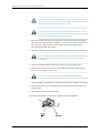
Chassis Lifting Guidelines for EX2200 Switches . . . . . . . . . . . . . . . . . . . . . . . . . . 128
Copyright © 2010, Juniper Networks, Inc.
ix
Complete Hardware Guide for EX2200 Ethernet Switches
Ramp Warning for EX Series Switches . . . . . . . . . . . . . . . . . . . . . . . . . . . . . . . . . . 129
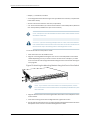
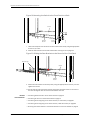
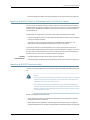
Rack-Mounting and Cabinet-Mounting Warnings for EX Series Switches . . . . . . 129
Wall-Mounting Warnings for EX2200 Switches . . . . . . . . . . . . . . . . . . . . . . . . . . 134
Grounded Equipment Warning for EX Series Switches . . . . . . . . . . . . . . . . . . . . . 134
Maintenance and Operational Safety Guidelines and Warnings for EX Series
Switches . . . . . . . . . . . . . . . . . . . . . . . . . . . . . . . . . . . . . . . . . . . . . . . . . . . . . . 135
Jewelry Removal Warning . . . . . . . . . . . . . . . . . . . . . . . . . . . . . . . . . . . . . . . . 135
Lightning Activity Warning . . . . . . . . . . . . . . . . . . . . . . . . . . . . . . . . . . . . . . . . 137
Operating Temperature Warning . . . . . . . . . . . . . . . . . . . . . . . . . . . . . . . . . . 138
Product Disposal Warning . . . . . . . . . . . . . . . . . . . . . . . . . . . . . . . . . . . . . . . . 139
Chapter 18
Power and Electrical Safety Information . . . . . . . . . . . . . . . . . . . . . . . . . . . . . 141
General Electrical Safety Guidelines and Warnings for EX Series Switches . . . . . 141
Prevention of Electrostatic Discharge Damage on EX Series Switches . . . . . . . . 142
AC Power Electrical Safety Guidelines for EX Series Switches . . . . . . . . . . . . . . . 144
AC Power Disconnection Warning for EX Series Switches . . . . . . . . . . . . . . . . . . 145
TN Power Warning for EX Series Switches . . . . . . . . . . . . . . . . . . . . . . . . . . . . . . 146
In Case of Electrical Accident: Action to Take on an EX Series Switch . . . . . . . . . 147
Part 8
Compliance Information
Chapter 19
Compliance Information . . . . . . . . . . . . . . . . . . . . . . . . . . . . . . . . . . . . . . . . . . . 151
Agency Approvals for EX Series Switches . . . . . . . . . . . . . . . . . . . . . . . . . . . . . . . 151
Compliance Statements for EMC Requirements for EX Series Switches . . . . . . . 152
Canada . . . . . . . . . . . . . . . . . . . . . . . . . . . . . . . . . . . . . . . . . . . . . . . . . . . . . . . 152
European Community . . . . . . . . . . . . . . . . . . . . . . . . . . . . . . . . . . . . . . . . . . . 153
Japan . . . . . . . . . . . . . . . . . . . . . . . . . . . . . . . . . . . . . . . . . . . . . . . . . . . . . . . . 153
United States . . . . . . . . . . . . . . . . . . . . . . . . . . . . . . . . . . . . . . . . . . . . . . . . . . 153
FCC Part 15 Statement . . . . . . . . . . . . . . . . . . . . . . . . . . . . . . . . . . . . . . . . . . 153
Non-Regulatory Environmental Standards . . . . . . . . . . . . . . . . . . . . . . . . . . 154
Compliance Statements for Acoustic Noise for EX Series Switches . . . . . . . . . . 154
Declaration of Conformity for EX2200 Switches . . . . . . . . . . . . . . . . . . . . . . . . . . 155
x
Copyright © 2010, Juniper Networks, Inc.
List of Figures
Part 1
Switch and Components Overview and Specifications
Chapter 1
EX2200 Switch Overview . . . . . . . . . . . . . . . . . . . . . . . . . . . . . . . . . . . . . . . . . . . 3
Figure 1: Front Panel of an EX2200 Switch with 48 Gigabit Ethernet Ports . . . . . . 6
Figure 2: Front Panel of an EX2200 Switch with 24 Gigabit Ethernet Ports . . . . . . 6
Figure 3: Rear Panel of an EX2200 Switch . . . . . . . . . . . . . . . . . . . . . . . . . . . . . . . . 7
Chapter 2
Component Descriptions . . . . . . . . . . . . . . . . . . . . . . . . . . . . . . . . . . . . . . . . . . . 11
Figure 4: Chassis Status LEDs in an EX2200 Switch . . . . . . . . . . . . . . . . . . . . . . . . 11
Figure 5: LEDs on the Network Ports on the Front Panel . . . . . . . . . . . . . . . . . . . . . 12
Figure 6: LEDs on the Uplink Ports and Port Status Mode LEDs . . . . . . . . . . . . . . . 12
Figure 7: LEDs on the Management Port on an EX2200 Switch . . . . . . . . . . . . . . . 14
Figure 8: Airflow Through Non-PoE Models of EX2200 Switches . . . . . . . . . . . . . 16
Figure 9: Airflow Through PoE Models of EX2200 Switches . . . . . . . . . . . . . . . . . . 16
Part 2
Planning for Switch Installation
Chapter 5
Mounting and Clearance Requirements . . . . . . . . . . . . . . . . . . . . . . . . . . . . . . 39
Figure 10: Clearance Requirements for Airflow and Hardware Maintenance for
EX2200 Switches . . . . . . . . . . . . . . . . . . . . . . . . . . . . . . . . . . . . . . . . . . . . . . . 42
Figure 11: Airflow Through PoE Models of EX2200 Switches . . . . . . . . . . . . . . . . . 43
Figure 12: Airflow Through Non-PoE Models of EX2200 Switches . . . . . . . . . . . . 43
Chapter 7
Planning Power Requirements . . . . . . . . . . . . . . . . . . . . . . . . . . . . . . . . . . . . . . 47
Figure 13: AC Plug Types . . . . . . . . . . . . . . . . . . . . . . . . . . . . . . . . . . . . . . . . . . . . . 48
Part 3
Installing and Connecting the Switch and Switch Components
Chapter 8
Installing the Switch . . . . . . . . . . . . . . . . . . . . . . . . . . . . . . . . . . . . . . . . . . . . . . . 51
Figure 14: Attaching Rubber Feet to a Switch Chassis . . . . . . . . . . . . . . . . . . . . . . 55
Figure 15: Attaching the Mounting Bracket Along the Front of the Switch . . . . . . 56
Figure 16: Mounting the Switch on Two Posts in a Rack . . . . . . . . . . . . . . . . . . . . . 57
Figure 17: Attaching the Front Bracket to the Side-Rail Bracket . . . . . . . . . . . . . . . 59
Figure 18: Attaching the Side-Rail Bracket to the Switch Chassis . . . . . . . . . . . . . 59
Figure 19: Mounting the Switch to the Front Posts in a Rack . . . . . . . . . . . . . . . . . 60
Figure 20: Sliding the Rear Brackets to the Rear of a Four-Post Rack . . . . . . . . . . 60
Figure 21: Attaching Wall-Mount Brackets to a Switch Chassis . . . . . . . . . . . . . . . 62
Figure 22: Measuring for Mounting Screws . . . . . . . . . . . . . . . . . . . . . . . . . . . . . . . 63
Figure 23: Mounting a Switch on a Wall . . . . . . . . . . . . . . . . . . . . . . . . . . . . . . . . . 64
Chapter 9
Installing Switch Components . . . . . . . . . . . . . . . . . . . . . . . . . . . . . . . . . . . . . . 65
Figure 24: Installing a Transceiver in an EX Series Switch . . . . . . . . . . . . . . . . . . . 66
Copyright © 2010, Juniper Networks, Inc.
xi
Complete Hardware Guide for EX2200 Ethernet Switches
Chapter 10
Connecting the Switch . . . . . . . . . . . . . . . . . . . . . . . . . . . . . . . . . . . . . . . . . . . . . 67
Figure 25: Connecting a Grounding Cable to an EX Series Switch . . . . . . . . . . . . . 67
Figure 26: Connecting the Grounding Lug to an EX4200 Switch on a Four-Post
Rack . . . . . . . . . . . . . . . . . . . . . . . . . . . . . . . . . . . . . . . . . . . . . . . . . . . . . . . . . . 70
Figure 27: Connecting an AC Power Cord Retainer Clip to the AC Power Cord
Inlet on an EX2200 Switch . . . . . . . . . . . . . . . . . . . . . . . . . . . . . . . . . . . . . . . . 74
Figure 28: Connecting an AC Power Cord to the AC Power Cord Inlet on an
EX2200 Switch . . . . . . . . . . . . . . . . . . . . . . . . . . . . . . . . . . . . . . . . . . . . . . . . . 74
Figure 29: Ethernet Cable Connector . . . . . . . . . . . . . . . . . . . . . . . . . . . . . . . . . . . . 75
Figure 30: Connecting an EX Series Switch to a Network for Out-of-Band
Management . . . . . . . . . . . . . . . . . . . . . . . . . . . . . . . . . . . . . . . . . . . . . . . . . . . 75
Figure 31: Ethernet Cable Connector . . . . . . . . . . . . . . . . . . . . . . . . . . . . . . . . . . . . 76
Figure 32: Connecting an EX Series Switch to a Management Console Through
a Console Server . . . . . . . . . . . . . . . . . . . . . . . . . . . . . . . . . . . . . . . . . . . . . . . . 77
Figure 33: Connecting an EX Series Switch Directly to a Management
Console . . . . . . . . . . . . . . . . . . . . . . . . . . . . . . . . . . . . . . . . . . . . . . . . . . . . . . . 77
Figure 34: Ethernet Cable Connector . . . . . . . . . . . . . . . . . . . . . . . . . . . . . . . . . . . 80
Figure 35: Connecting a Fiber-Optic Cable to an Optical Transceiver Installed in
an EX Series Switch . . . . . . . . . . . . . . . . . . . . . . . . . . . . . . . . . . . . . . . . . . . . . 82
Chapter 11
Performing Initial Configuration . . . . . . . . . . . . . . . . . . . . . . . . . . . . . . . . . . . . . 83
Figure 36: LCD Panel in an EX3200, EX4200, EX4500, or EX8200 Switch . . . . . 90
Part 4
Removing Switch Components
Chapter 12
Removing Switch Components . . . . . . . . . . . . . . . . . . . . . . . . . . . . . . . . . . . . . 95
Figure 37: Removing a Transceiver from an EX Series Switch . . . . . . . . . . . . . . . . 96
Part 6
Returning Hardware
Chapter 14
Returning the Switch or Switch Components . . . . . . . . . . . . . . . . . . . . . . . . 105
Figure 38: Location of the Serial Number ID Label on EX2200 Switches . . . . . . . 107
Part 7
Safety Information
Chapter 18
Power and Electrical Safety Information . . . . . . . . . . . . . . . . . . . . . . . . . . . . . 141
Figure 39: Place a Component into an Antistatic Bag . . . . . . . . . . . . . . . . . . . . . . 143
xii
Copyright © 2010, Juniper Networks, Inc.
List of Tables
Part 1
Switch and Components Overview and Specifications
Chapter 1
EX2200 Switch Overview . . . . . . . . . . . . . . . . . . . . . . . . . . . . . . . . . . . . . . . . . . . 3
Table 1: EX2200 Switch Models . . . . . . . . . . . . . . . . . . . . . . . . . . . . . . . . . . . . . . . . . 4
Table 2: Physical Specifications of the EX2200 Switch Chassis . . . . . . . . . . . . . . . 5
Table 3: CLI Equivalents of Terms Used in Documentation for EX2200
Switches . . . . . . . . . . . . . . . . . . . . . . . . . . . . . . . . . . . . . . . . . . . . . . . . . . . . . . . 8
Chapter 2
Component Descriptions . . . . . . . . . . . . . . . . . . . . . . . . . . . . . . . . . . . . . . . . . . . 11
Table 4: Chassis Status LEDs in an EX2200 Switch . . . . . . . . . . . . . . . . . . . . . . . . . 11
Table 5: Link/Activity LED on the Network Ports and Uplink Ports in EX2200
Switches . . . . . . . . . . . . . . . . . . . . . . . . . . . . . . . . . . . . . . . . . . . . . . . . . . . . . . . 12
Table 6: Status LED on the Network Ports and Uplink Ports in EX2200
Switches . . . . . . . . . . . . . . . . . . . . . . . . . . . . . . . . . . . . . . . . . . . . . . . . . . . . . . . 13
Table 7: Link/Activity LED on the Management Port on an EX2200 Switch . . . . . . 14
Table 8: Status LED on the Management Port on an EX2200 Switch . . . . . . . . . . 14
Table 9: Power Consumed by EX2200 Switches . . . . . . . . . . . . . . . . . . . . . . . . . . . 15
Chapter 3
Component Specifications . . . . . . . . . . . . . . . . . . . . . . . . . . . . . . . . . . . . . . . . . 19
Table 10: Network Port Connector Pinout Information for EX2200 Switches . . . . 20
Table 11: EX Series Switches Console Port Connector Pinout Information . . . . . . . 21
Table 12: Management Port Connector Pinout Information for EX2200
Switches . . . . . . . . . . . . . . . . . . . . . . . . . . . . . . . . . . . . . . . . . . . . . . . . . . . . . . 22
Table 13: Optical Interface Support and Copper Interface Support for Gigabit
Ethernet SFP Transceivers in EX2200 Switches . . . . . . . . . . . . . . . . . . . . . . . 23
Table 14: Optical Interface Support for Fast Ethernet SFP Transceivers in EX2200
Switches . . . . . . . . . . . . . . . . . . . . . . . . . . . . . . . . . . . . . . . . . . . . . . . . . . . . . . 27
Part 2
Planning for Switch Installation
Chapter 4
Site Preparation . . . . . . . . . . . . . . . . . . . . . . . . . . . . . . . . . . . . . . . . . . . . . . . . . . . 33
Table 15: Site Preparation Checklist . . . . . . . . . . . . . . . . . . . . . . . . . . . . . . . . . . . . 33
Table 16: Site Electrical Wiring Guidelines . . . . . . . . . . . . . . . . . . . . . . . . . . . . . . . . 36
Table 17: EX Series Switch Environmental Tolerances . . . . . . . . . . . . . . . . . . . . . . 37
Chapter 5
Mounting and Clearance Requirements . . . . . . . . . . . . . . . . . . . . . . . . . . . . . . 39
Table 18: Rack Requirements and Specifications for the Switch . . . . . . . . . . . . . . 39
Table 19: Cabinet Requirements and Specifications for the Switch . . . . . . . . . . . . 41
Chapter 7
Planning Power Requirements . . . . . . . . . . . . . . . . . . . . . . . . . . . . . . . . . . . . . . 47
Table 20: AC Power Supply Electrical Specifications for EX2200 Switches . . . . . 47
Table 21: AC Power Cord Specifications . . . . . . . . . . . . . . . . . . . . . . . . . . . . . . . . . 48
Copyright © 2010, Juniper Networks, Inc.
xiii
Complete Hardware Guide for EX2200 Ethernet Switches
Part 3
Installing and Connecting the Switch and Switch Components
Chapter 8
Installing the Switch . . . . . . . . . . . . . . . . . . . . . . . . . . . . . . . . . . . . . . . . . . . . . . . 51
Table 22: Inventory of Components Provided with an EX2200 Switch . . . . . . . . . 52
Chapter 10
Connecting the Switch . . . . . . . . . . . . . . . . . . . . . . . . . . . . . . . . . . . . . . . . . . . . . 67
Table 23: Port Settings . . . . . . . . . . . . . . . . . . . . . . . . . . . . . . . . . . . . . . . . . . . . . . . 79
xiv
Copyright © 2010, Juniper Networks, Inc.
About This Topic Collection
•
How to Use This Guide on page xv
•
List of EX Series Guides for Junos OS Release 10.4 on page xv
•
Downloading Software on page xvii
•
Documentation Symbols Key on page xviii
•
Documentation Feedback on page xix
•
Requesting Technical Support on page xx
How to Use This Guide
Complete documentation for the EX Series product family is provided on webpages at
http://www.juniper.net/techpubs/en_US/release-independent/information-products/
pathway-pages/ex-series/product/index.html. We have selected content from these
webpages and created a number of EX Series guides that collect related topics into a
book-like format so that the information is easy to print and easy to download to your
local computer.
This guide, Complete Hardware Guide for EX2200 Switches, collects together information
about the EX2200 fixed-configuration switches. The release notes are at
http://www.juniper.net/techpubs/en_US/junos10.4/information-products/topic-collections/
release-notes/10.4/junos-release-notes-10.4.pdf.
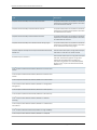
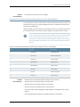
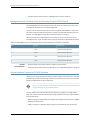
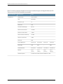
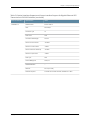
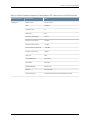
List of EX Series Guides for Junos OS Release 10.4
Title
Description
Complete Hardware Guide for EX2200 Ethernet Switches
Component descriptions, site preparation, installation,
replacement, and safety and compliance information
for EX2200 Ethernet switches
Complete Hardware Guide for EX3200 Ethernet Switches
Component descriptions, site preparation, installation,
replacement, and safety and compliance information
for EX3200 Ethernet switches
Complete Hardware Guide for EX4200 Ethernet Switches
Component descriptions, site preparation, installation,
replacement, and safety and compliance information
for EX4200 Ethernet switches
Copyright © 2010, Juniper Networks, Inc.
xv
Complete Hardware Guide for EX2200 Ethernet Switches
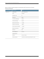
Title
Description
Complete Hardware Guide for EX4500 Ethernet Switches
Component descriptions, site preparation, installation,
replacement, and safety and compliance information
for EX4500 Ethernet switches
Complete Hardware Guide for EX8208 Ethernet Switches
Component descriptions, site preparation, installation,
replacement, and safety and compliance information
for EX8208 Ethernet switches
Complete Hardware Guide for EX8216 Ethernet Switches
Component descriptions, site preparation, installation,
replacement, and safety and compliance information
for EX8216 Ethernet switches
Complete Hardware Guide for the XRE200 External Routing Engine
Component descriptions, site preparation, installation,
replacement, and safety and compliance information
for the XRE200 External Routing Engine
®
Complete Software Guide for Junos OS for EX Series Ethernet Switches,
Release 10.4
Software feature descriptions, configuration examples,
and tasks for Junos OS for EX Series switches
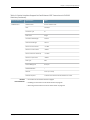
Software Topic Collections
Software feature descriptions, configuration examples
and tasks, and reference pages for configuration
statements and operational commands (This
information also appears in the Complete Software
®
Guide for Junos OS for EX Series Ethernet Switches,
Release 10.4.)
®
Junos OS for EX Series Ethernet Switches, Release 10.4: EX4200 Virtual
Chassis
®
Junos OS for EX Series Ethernet Switches, Release 10.4: EX8200 Virtual
Chassis
®
Junos OS for EX Series Ethernet Switches, Release 10.4: Access Control
®
Junos OS for EX Series Ethernet Switches, Release 10.4: Configuration
Management
®
Junos OS for EX Series Ethernet Switches, Release 10.4: Class of Service
®
Junos OS for EX Series Ethernet Switches, Release 10.4: Device Security
®
Junos OS for EX Series Ethernet Switches, Release 10.4: Ethernet
Switching
®
Junos OS for EX Series Ethernet Switches, Release 10.4: Fibre Channel
over Ethernet
®
Junos OS for EX Series Ethernet Switches, Release 10.4: High Availability
®
Junos OS for EX Series Ethernet Switches, Release 10.4: Interfaces
xvi
Copyright © 2010, Juniper Networks, Inc.
About This Topic Collection
Title
Description
®
Junos OS for EX Series Ethernet Switches, Release 10.4: Layer 3
Protocols
®
Junos OS for EX Series Ethernet Switches, Release 10.4: MPLS
®
Junos OS for EX Series Ethernet Switches, Release 10.4: Multicast
®
Junos OS for EX Series Switches, Release 10.4: Network Management
and Monitoring
®
Junos OS for EX Series Switches, Release 10.4: Port Security
®
Junos OS for EX Series Ethernet Switches, Release 10.4: Routing Policy
and Packet Filtering
®
Junos OS for EX Series Ethernet Switches, Release 10.4: Software
Installation
®
Junos OS for EX Series Ethernet Switches, Release 10.4: Spanning-Tree
Protocols
®
Junos OS for EX Series Ethernet Switches, Release 10.4: System
Monitoring
®
Junos OS for EX Series Ethernet Switches, Release 10.4: System Services
®
Junos OS for EX Series Ethernet Switches, Release 10.4: System Setup
®
Junos OS for EX Series Ethernet Switches, Release 10.4: User and Access
Management
®
Junos OS for EX Series Ethernet Switches, Release 10.4: User Interfaces
Downloading Software
You can download Junos OS for EX Series switches from the Download Software area
at http://www.juniper.net/customers/support/ . To download the software, you must
have a Juniper Networks user account. For information about obtaining an account, see
http://www.juniper.net/entitlement/setupAccountInfo.do.
Copyright © 2010, Juniper Networks, Inc.
xvii
Complete Hardware Guide for EX2200 Ethernet Switches
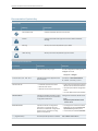
Documentation Symbols Key
Notice Icons
Icon
Meaning
Description
Informational note
Indicates important features or instructions.
Caution
Indicates a situation that might result in loss of data or hardware
damage.
Warning
Alerts you to the risk of personal injury or death.
Laser warning
Alerts you to the risk of personal injury from a laser.
Text and Syntax Conventions
Convention
Description
Examples
Bold text like this
Represents text that you type.
To enter configuration mode, type the
configure command:
user@host> configure
Fixed-width text like this
Italic text like this
Italic text like this
Plain text like this
< > (angle brackets)
xviii
Represents output that appears on the
terminal screen.
user@host> show chassis alarms
•
Introduces important new terms.
•
•
Identifies book names.
A policy term is a named structure that
defines match conditions and actions.
•
Identifies RFC and Internet draft titles.
•
Junos OS System Basics Configuration
Guide
•
RFC 1997, BGP Communities Attribute
No alarms currently active
Represents variables (options for which
you substitute a value) in commands or
configuration statements.
Configure the machine’s domain name:
Represents names of configuration
statements, commands, files, and
directories; IP addresses; configuration
hierarchy levels; or labels on routing
platform components.
•
To configure a stub area, include the
stub statement at the [edit protocols
ospf area area-id] hierarchy level.
•
The console port is labeled CONSOLE.
Enclose optional keywords or variables.
stub <default-metric metric>;
[edit]
root@# set system domain-name
domain-name
Copyright © 2010, Juniper Networks, Inc.
About This Topic Collection
Text and Syntax Conventions
Convention
Description
Examples
| (pipe symbol)
Indicates a choice between the mutually
exclusive keywords or variables on either
side of the symbol. The set of choices is
often enclosed in parentheses for clarity.
broadcast | multicast
# (pound sign)
Indicates a comment specified on the
same line as the configuration statement
to which it applies.
rsvp { # Required for dynamic MPLS only
[ ] (square brackets)
Enclose a variable for which you can
substitute one or more values.
community name members [
community-ids ]
Indention and braces ( { } )
Identify a level in the configuration
hierarchy.
; (semicolon)
Identifies a leaf statement at a
configuration hierarchy level.
(string1 | string2 | string3)
[edit]
routing-options {
static {
route default {
nexthop address;
retain;
}
}
}
J-Web GUI Conventions
Bold text like this
Represents J-Web graphical user
interface (GUI) items you click or select.
> (bold right angle bracket)
Separates levels in a hierarchy of J-Web
selections.
•
In the Logical Interfaces box, select All
Interfaces.
•
To cancel the configuration, click
Cancel.
In the configuration editor hierarchy,
select Protocols>Ospf.
Documentation Feedback
We encourage you to provide feedback, comments, and suggestions so that we can
improve the documentation. Send e-mail to [email protected] with the
following:
•
Document URL or title
•
Page number if applicable
•
Software version
•
Your name and company
Copyright © 2010, Juniper Networks, Inc.
xix
Complete Hardware Guide for EX2200 Ethernet Switches
Requesting Technical Support
Technical product support is available through the Juniper Networks Technical Assistance
Center (JTAC). If you are a customer with an active J-Care or JNASC support contract,
or are covered under warranty, and need post-sales technical support, you can access
our tools and resources online or open a case with JTAC.
•
JTAC policies—For a complete understanding of our JTAC procedures and policies,
review the JTAC User Guide located at
http://www.juniper.net/us/en/local/pdf/resource-guides/7100059-en.pdf .
•
Product warranties—For product warranty information, visit
http://www.juniper.net/support/warranty/ .
•
JTAC hours of operation—The JTAC centers have resources available 24 hours a day,
7 days a week, 365 days a year.
Self-Help Online Tools and Resources
For quick and easy problem resolution, Juniper Networks has designed an online
self-service portal called the Customer Support Center (CSC) that provides you with the
following features:
•
Find CSC offerings: http://www.juniper.net/customers/support/
•
Search for known bugs: http://www2.juniper.net/kb/
•
Find product documentation: http://www.juniper.net/techpubs/
•
Find solutions and answer questions using our Knowledge Base: http://kb.juniper.net/
•
Download the latest versions of software and review release notes:
http://www.juniper.net/customers/csc/software/
•
Search technical bulletins for relevant hardware and software notifications:
https://www.juniper.net/alerts/
•
Join and participate in the Juniper Networks Community Forum:
http://www.juniper.net/company/communities/
•
Open a case online in the CSC Case Management tool: http://www.juniper.net/cm/
To verify service entitlement by product serial number, use our Serial Number Entitlement
(SNE) Tool: https://tools.juniper.net/SerialNumberEntitlementSearch/
Opening a Case with JTAC
You can open a case with JTAC on the Web or by telephone.
•
Use the Case Management tool in the CSC at http://www.juniper.net/cm/ .
•
Call 1-888-314-JTAC (1-888-314-5822 toll-free in the USA, Canada, and Mexico).
For international or direct-dial options in countries without toll-free numbers, see
http://www.juniper.net/support/requesting-support.html .
xx
Copyright © 2010, Juniper Networks, Inc.
PART 1
Switch and Components Overview and
Specifications
•
EX2200 Switch Overview on page 3
•
Component Descriptions on page 11
•
Component Specifications on page 19
Copyright © 2010, Juniper Networks, Inc.
1
Complete Hardware Guide for EX2200 Ethernet Switches
2
Copyright © 2010, Juniper Networks, Inc.
CHAPTER 1
EX2200 Switch Overview
•
EX2200 Switches Hardware Overview on page 3
•
EX2200 Switch Models on page 4
•
Chassis Physical Specifications for EX2200 Switches on page 5
•
Front Panel of an EX2200 Switch on page 5
•
Rear Panel of an EX2200 Switch on page 6
•
EX2200 Switch Hardware and CLI Terminology Mapping on page 7
EX2200 Switches Hardware Overview
Juniper Networks EX Series Ethernet Switches provide scalable connectivity for the
enterprise market, including branch offices, campus locations, and data centers. The
switches run under the Juniper Networks Junos operating system (Junos OS), which
provides Layer 2 and Layer 3 switching, routing, and security services. The same Junos
OS code base that runs on EX Series switches also runs on all Juniper Networks J Series,
M Series, MX Series, and T Series routers.
•
EX2200 Switches on page 3
•
Uplink Ports on page 3
•
Power over Ethernet (PoE) Ports on page 4
EX2200 Switches
Juniper Networks EX2200 Ethernet switches provide connectivity for low-density
environments.
EX2200 switches are available in models with either 24 or 48 built-in network ports and
four uplink ports, with Power over Ethernet (PoE) either available in all built-in network
ports or not available in any built-in network port. All models provide network ports that
have 10/100/1000Base-T Gigabit Ethernet connectors and four uplink ports. These
switches run under Junos OS for EX Series switches.
Uplink Ports
Each EX2200 switch has four uplink ports that support 1-gigabit small form-factor
pluggable (SFP) transceivers for use with fiber connections and copper connections.
See “Optical Interface Support in EX2200 Switches” on page 22.
Copyright © 2010, Juniper Networks, Inc.
3
Complete Hardware Guide for EX2200 Ethernet Switches
Power over Ethernet (PoE) Ports
PoE ports provide electrical current to devices through the network cables so that separate
power cords for devices such as IP phones, wireless access points, and security cameras
are unnecessary. EX2200 switches are available with full (all 24 or 48 built-in network
ports) or no PoE capability. Full PoE models are primarily used in IP telephony
environments.
EX2200 switches running Junos OS Release 10.3 or later can supply up to 30 W to
individual PoE ports, supporting powered devices that comply with IEEE 802.3af (PoE)
and IEEE 802.3at (PoE+).
NOTE: IEEE 802.3at class 4 powered devices require category 5 or higher
Ethernet cables.
EX2200 switches running Junos OS Release 10.2 or earlier can supply up to 15.4 W to
individual PoE ports, supporting powered devices that comply with IEEE 802.3af (PoE).
Related
Documentation
•
EX2200 Switch Models on page 4
•
Site Preparation Checklist for EX2200 Switches on page 33
EX2200 Switch Models
The EX2200 switch is available with 24 or 48 built-in network ports with full (all 24 or
48 built-in network ports) or no Power over Ethernet (PoE) capability. Table 1 on page 4
lists the EX2200 switch models.
Table 1: EX2200 Switch Models
Model
Access Ports
Ports in Which PoE Is Available
Maximum PoE Power
Available
EX2200-24T-4G
24 Gigabit Ethernet
–
–
EX2200-24P-4G
24 Gigabit Ethernet
All 24 ports
405 W
EX2200-48T-4G
48 Gigabit Ethernet
–
–
EX2200-48P-4G
48 Gigabit Ethernet
All 48 ports
405 W
Related
Documentation
4
•
Front Panel of an EX2200 Switch on page 5
•
EX2200 Switches Hardware Overview on page 3
Copyright © 2010, Juniper Networks, Inc.
Chapter 1: EX2200 Switch Overview
Chassis Physical Specifications for EX2200 Switches
The EX2200 switch chassis is a rigid sheet-metal structure that houses the hardware
components. Table 2 on page 5 summarizes the physical specifications of the EX2200
switch chassis.
Table 2: Physical Specifications of the EX2200 Switch Chassis
Description
Value
Chassis height
1.75 in. (4.45 cm)
Chassis width
•
17.5 in. (44.5 cm)
•
19 in. (48.2 cm) with mounting brackets attached
Chassis depth
10.5 in. (26.7 cm)
Weight
•
EX2200-24T: 6 lb (2.7 kg)
•
EX2200-24P: 8 lb (3.6 kg)
•
EX2200-48T: 8 lb (3.6 kg)
•
EX2200-48P: 10 lb (4.5 kg)
Related
Documentation
•
Rack Requirements for EX2200 Switches on page 39
•
Cabinet Requirements for EX2200 Switches on page 40
•
Mounting an EX2200 Switch on page 53
•
Installing and Connecting an EX2200 Switch on page 51
Front Panel of an EX2200 Switch
The front panel of an EX2200 switch consists of the following components:
•
Network ports—depending on the switch model, either of:
•
24 or 48 10/100/1000Base-T Gigabit Ethernet ports, with Power over Ethernet (PoE)
not available in EX2200-24T and EX2200-48T
•
24 or 48 10/100/1000Base-T Gigabit Ethernet ports, with Power over Ethernet (PoE)
available in EX2200-24P and EX2200-48P
•
4 built-in SFP uplink ports
•
2 chassis status LEDs
•
4 port status mode LEDs
•
Mode button
Figure 1 on page 6 shows the front panel of an EX2200 switch with 48 Gigabit Ethernet
ports. Figure 2 on page 6 shows the front panel of an EX2200 switch with 24 Gigabit
Ethernet ports.
Copyright © 2010, Juniper Networks, Inc.
5
Complete Hardware Guide for EX2200 Ethernet Switches
Figure 1: Front Panel of an EX2200 Switch with 48 Gigabit Ethernet Ports
Chassis
status
LEDs
0
1
2
3
4
5
6
7
8
9
10
12
11
13
14
15
16
17
18
19
20
21
22
23
24
25
26
27
28
29
30
31
32
33
34
35
36
37
38
39
40
41
42
43
44
45
46
47
M
S
AL
SY
SPD
DX
0
1
2
3
EN
Port status mode LEDs
Network
ports
Mode
button
SFP
uplink
ports
g027000
POE
Figure 2: Front Panel of an EX2200 Switch with 24 Gigabit Ethernet Ports
Chassis
status
LEDs
0
1
2
3
4
5
6
7
8
9
10
11
12
13
14
15
16
17
18
19
20
21
22
23
M
S
AL
SY
SPD
DX
0
1
2
3
EN
Port status mode LEDs
Network
ports
Related
Documentation
SFP
uplink
ports
Mode
button
g027002
POE
•
Chassis Status LEDs in EX2200 Switches on page 11
•
Network Port and Uplink Port LEDs in EX2200 Switches on page 12
•
Network Port Connector Pinout Information for an EX2200 Switch on page 20
•
Rear Panel of an EX2200 Switch on page 6
•
Installing a Transceiver in an EX Series Switch on page 65
•
Removing a Transceiver from an EX Series Switch on page 95
•
Installing and Connecting an EX2200 Switch on page 51
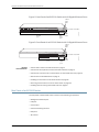
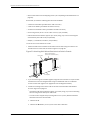
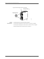
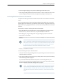
Rear Panel of an EX2200 Switch
The rear panel of the EX2200 switch consists of the following components:
6
•
Management Ethernet port
•
USB port
•
Console port
•
Protective earthing terminal
•
ESD point
•
Air exhaust
Copyright © 2010, Juniper Networks, Inc.
Chapter 1: EX2200 Switch Overview
•
Serial number ID label
•
AC power cord inlet
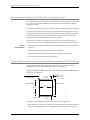
Figure 3 on page 7 shows the rear panel of an EX2200 switch.
All EX2200 switches have three exhaust openings on the rear panel. The two leftmost
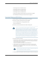
exhaust openings have fans behind them and are open. The rightmost exhaust opening
is open on Power over Ethernet (PoE) models and closed on non-PoE models. On PoE
models, this opening exhausts the air from the fan at the air intake for the power supply
on the side panel.
The power cord retainer clips extend out of the chassis by 3 in.
Figure 3: Rear Panel of an EX2200 Switch
Protective
ESD
earthing terminal point
Management
Ethernet port
Air intake with fan for power supply
(fan on PoE models only)
EX2200-24-4G REV: X1
Mfg. Date
20090227
g027001
750-026464 REV: X3
MAC: 00:23:9C:oE:19:00
MADE IN CHINA
USB
port
Console
port
Related
Documentation
Air exhaust
with fan
Air exhaust without fan
Serial number
(closed on non-PoE models)
ID label
AC power
cord inlet
•
Front Panel of an EX2200 Switch on page 5
•
USB Port Specifications for an EX Series Switch on page 19
•
Cooling System and Airflow in an EX2200 Switch on page 15
•
Power Supply in EX2200 Switches on page 14
•
Prevention of Electrostatic Discharge Damage on EX Series Switches on page 142
•
Connecting Earth Ground to an EX Series Switch on page 67
•
Installing and Connecting an EX2200 Switch on page 51
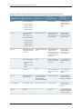
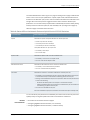
EX2200 Switch Hardware and CLI Terminology Mapping
This topic describes the hardware terms used in EX2200 switch documentation and the
corresponding terms used in the Junos OS command line interface (CLI). See Table 3 on
page 8.
Copyright © 2010, Juniper Networks, Inc.
7
Complete Hardware Guide for EX2200 Ethernet Switches
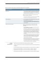
Table 3: CLI Equivalents of Terms Used in Documentation for EX2200 Switches
Hardware Item (CLI)
Description (CLI)
Value (CLI)
Item in
Documentation
Additional
Information
Chassis
One of the following:
–
Switch chassis
“Chassis Physical
Specifications for
EX2200 Switches” on
page 5
Value of n is always 0.
The switch does not
have actual FPCs. In
this case, FPC refers to
the switch itself.
Understanding
Interface Naming
Conventions on EX
Series Switches
Abbreviated name of
the Physical Interface
Card (PIC)
n is a value in the range
of 0-1.
The switch does not
have actual PIC
devices; see entries for
PIC 0 through PIC 1 for
the equivalent item on
the switch.
Understanding
Interface Naming
Conventions on EX
Series Switches
One of the following:
PIC 0
Built-in network ports
on the front panel of
the switch
“Front Panel of an
EX2200 Switch” on
page 5
4x GE SFP
PIC 1
Built-in uplink ports on
the front panel of the
switch
“Front Panel of an
EX2200 Switch” on
page 5
Xcvr (n)
Abbreviated name of
the transceiver
n is a value equivalent
to the number of the
port in which the
transceiver is installed.
Optical transceivers
“Optical Interface
Support in EX2200
Switches” on page 22
Power supply (n)
Built-in power supply
Value of n is always 0.
AC power supply
“Power Supply in
EX2200 Switches” on
page 14
Fan tray
Fan tray
–
Fan tray
“Cooling System and
Airflow in an EX2200
Switch” on page 15
FPC (n)
•
EX2200-24T-4G
•
EX2200-24P-4G
•
EX2200-48T-4G
•
EX2200-48P-4G
Abbreviated name of
the Flexible PIC
Concentrator (FPC)
One of the following:
PIC (n)
8
•
EX2200-24T-4G
•
EX2200-24P-4G
•
EX2200-48T-4G
•
EX2200-48P-4G
•
24x 10/100/1000
Base-T
•
48x 10/100/1000
Base-T
Copyright © 2010, Juniper Networks, Inc.
Chapter 1: EX2200 Switch Overview
Related
Documentation
•
EX Series Switches Hardware and CLI Terminology Mapping
•
EX2200 Switches Hardware Overview on page 3
Copyright © 2010, Juniper Networks, Inc.
9
Complete Hardware Guide for EX2200 Ethernet Switches
10
Copyright © 2010, Juniper Networks, Inc.
CHAPTER 2
Component Descriptions
•
Chassis Status LEDs in EX2200 Switches on page 11
•
Network Port and Uplink Port LEDs in EX2200 Switches on page 12
•
Management Port LEDs in EX2200 Switches on page 14
•
Power Supply in EX2200 Switches on page 14
•
Cooling System and Airflow in an EX2200 Switch on page 15
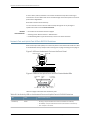
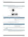
Chassis Status LEDs in EX2200 Switches
The front panel of an EX2200 switch has two chassis status LEDs labeled SYS and ALM
on the far right side of the panel, above the uplink ports (see Figure 4 on page 11).
Figure 4: Chassis Status LEDs in an EX2200 Switch
Chassis
status LEDs
M
S
AL
SY
SPD
1
2
3
EN
POE
g027003
DX
0
Table 4 on page 11 describes the chassis status LEDs in an EX2200 switch, their colors
and states, and the status they indicate.
Table 4: Chassis Status LEDs in an EX2200 Switch
LED Label
Color
State and Description
ALM
Unlit
There is no alarm.
Amber
There is a minor alarm.
Red
There is a major alarm.
Green
•
On steadily—The switch is functioning normally.
•
Blinking—The switch is booting.
•
Off—The switch is off.
SYS
A major alarm (red) indicates a critical error condition that requires immediate action.
Copyright © 2010, Juniper Networks, Inc.
11
Complete Hardware Guide for EX2200 Ethernet Switches
A minor alarm (amber) indicates a noncritical condition that requires monitoring or
maintenance. A minor alarm that is left unchecked might cause interruption in service or
performance degradation.
Both LEDs can be lit simultaneously.
You can view the colors of the two LEDs remotely through the CLI by issuing the
operational mode command show chassis led.
Related
Documentation
•
Front Panel of an EX2200 Switch on page 5
•
Checking Active Alarms with the J-Web Interface
•
Understanding Alarm Types and Severity Levels on EX Series Switches
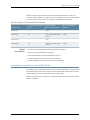
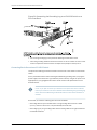
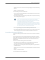
Network Port and Uplink Port LEDs in EX2200 Switches
Each network port and uplink port on the front panel of an EX2200 switch has two LEDs
that indicate link/activity and port status. See Figure 5 on page 12 and Figure 6 on page 12.
Figure 5: LEDs on the Network Ports on the Front Panel
Link/Activity LED
Status LED
0
1
2
3
4
6
5
7
8
9
10
12
11
14
13
15
16
17
18
19
20
21
22
23
g027005
0
1
Figure 6: LEDs on the Uplink Ports and Port Status Mode LEDs
Link/Activity
LED
Status
LED
Port status
mode LEDs
M
S
AL
SY
SPD
DX
1
2
3
EN
POE
Port 0
Port 1
Port 2
Mode
Port 3 button
g027007
0
Table 5 on page 12 describes the Link/Activity LED.
Table 5: Link/Activity LED on the Network Ports and Uplink Ports in EX2200 Switches
LED
Color
State and Description
Link/Activity
Green
•
Blinking—The port and the link are active, and there is link activity.
•
On steadily—The port and the link are active, but there is no link activity.
•
Off—The port is not active.
12
Copyright © 2010, Juniper Networks, Inc.
Chapter 2: Component Descriptions
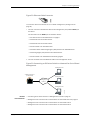
The LEDs labeled Status LED in Figure 5 on page 12 and Figure 6 on page 12 indicate the
status of one of the four port parameters—speed, duplex mode, administrative status,
and Power over Ethernet (PoE) status. Use the mode button below the POE LED on the
far right side of the front panel to toggle the Status LED to show the different port
parameters. You can tell which port parameter is indicated by the Status LED by seeing
which port status mode LED (SPD, DX, EN, and POE) is lit. (See Figure 6 on page 12).
Table 6 on page 13 describes the Status LED.
Table 6: Status LED on the Network Ports and Uplink Ports in EX2200 Switches
Port Parameters
State and Description
Speed
Indicates the speed. The speed indicators for network ports are:
•
One blink per second—10 Mbps
•
Two blinks per second—100 Mbps
•
Three blinks per second—1000 Mbps
The speed indicators for uplink ports are:
Duplex mode
•
On steadily—1000 Mbps
•
Off—10/100 Mbps
Indicates the duplex mode. The status indicators are:
Administrative status
•
On steadily—Port is set to full-duplex mode.
•
Off—Port is set to half-duplex mode.
Indicates the administrative status. The status indicators are:
PoE status
•
On steadily—Port is administratively enabled.
•
Off—Port is administratively disabled.
Indicates the PoE status. The status indicators for network ports are:
•
On steadily—PoE is available on the port, a device that draws power from the port
is connected to the port, and the device is drawing power from the port.
•
Blinking—PoE is available on the port, but no power is drawn from the port because
of one of the following:
•
•
No device that draws power from the port is connected to the port.
•
A device that draws power from the port is connected to the port, but the device
is not drawing any power from the port.
Off—PoE is not available on the port.
PoE is not available on uplink ports; therefore, the LED for those ports is always unlit.
You can tell which port parameter is indicated by the Status LED on network ports and
uplink ports by issuing the operational mode command show chassis led.
Related
Documentation
•
Front Panel of an EX2200 Switch on page 5
•
Configuring Gigabit Ethernet Interfaces (CLI Procedure)
•
Configuring Gigabit Ethernet Interfaces (J-Web Procedure)
Copyright © 2010, Juniper Networks, Inc.
13
Complete Hardware Guide for EX2200 Ethernet Switches
Management Port LEDs in EX2200 Switches
The management port on the rear panel of an EX2200 switch has two LEDs that indicate
link/activity and port status (see Figure 7 on page 14).
Figure 7: LEDs on the Management Port on an EX2200 Switch
Status
LED
g027006
Link/Activity
LED
Table 7 on page 14 describes the Link/Activity LED.
Table 7: Link/Activity LED on the Management Port on an EX2200 Switch
LED
Color
State and Description
Link/Activity
Green
•
Blinking—The port and the link are active, and there is link
activity.
•
On steadily—The port and the link are active, but there is no
link activity.
•
Off—The port is not active.
Table 8 on page 14 describes the Status LED.
Table 8: Status LED on the Management Port on an EX2200 Switch
LED
Color
State and Description
Status
Green
Indicates the speed. The speed indicators are:
Related
Documentation
•
•
One blink per second—10 Mbps
•
Two blinks per second—100 Mbps
Connecting an EX Series Switch to a Network for Out-of-Band Management on page 74
Power Supply in EX2200 Switches
The power supply in EX2200 switches is built in along the rear panel of the chassis, with
an AC power cord inlet on the rear panel to connect power to the switch.
14
Copyright © 2010, Juniper Networks, Inc.
Chapter 2: Component Descriptions
Table 9 on page 15 lists the power consumed by each EX2200 switch model. The
maximum power available on a PoE port is 30 W for switches running Junos OS Release
10.3 or later and 15.4 W for switches running Junos OS Release 10.2 or earlier.
Table 9: Power Consumed by EX2200 Switches
Model Number
Number of PoE-Enabled
Ports
Maximum Power
Consumed by the Switch
Maximum PoE Power
Available
EX2200-24T
–
50 W
–
EX2200-24P
24
60 W (when no PoE power is
drawn)
405 W
EX2200-48T
–
76 W
–
EX2200-48P
48
91 W (when no PoE power is
drawn)
405 W
Related
Documentation
•
AC Power Cord Specifications for EX2200 Switches on page 47
•
Rear Panel of an EX2200 Switch on page 6
•
Power Specifications for EX2200 Switches on page 47
•
Connecting AC Power to an EX2200 Switch on page 73
•
Connecting Earth Ground to an EX Series Switch on page 67
Cooling System and Airflow in an EX2200 Switch
The cooling system in an EX2200 switch consists of two fans along the rear of the chassis
that provide side-to-rear chassis cooling. In switch models with network ports in which
PoE is available, there is an additional fan in the power supply.
Figure 8 on page 16 shows the airflow in an EX2200 switch with network ports in which
PoE is not available.
Copyright © 2010, Juniper Networks, Inc.
15
Complete Hardware Guide for EX2200 Ethernet Switches
Figure 8: Airflow Through Non-PoE Models of EX2200 Switches
g027021
Chassis front
Fans
Chassis rear
Figure 9 on page 16 shows the airflow in an EX2200 switch with network ports in which
PoE is available.
Figure 9: Airflow Through PoE Models of EX2200 Switches
Fans
Fan
g027008
Chassis front
Chassis rear
Under normal operating conditions, the fans operate at reduced speed to reduce noise.
Temperature sensors in the chassis monitor the temperature within the chassis. If any
fan fails or if the temperature inside the chassis rises above the threshold, the switch
raises an alarm and all functioning fans operate at a higher speed than normal. If the
16
Copyright © 2010, Juniper Networks, Inc.
Chapter 2: Component Descriptions
temperature inside the chassis rises above the threshold, the switch shuts down
automatically.
Related
Documentation
•
Rear Panel of an EX2200 Switch on page 6
•
Chassis Status LEDs in EX2200 Switches on page 11
•
Understanding Alarm Types and Severity Levels on EX Series Switches
•
Prevention of Electrostatic Discharge Damage on EX Series Switches on page 142
Copyright © 2010, Juniper Networks, Inc.
17
Complete Hardware Guide for EX2200 Ethernet Switches
18
Copyright © 2010, Juniper Networks, Inc.
CHAPTER 3
Component Specifications
•
USB Port Specifications for an EX Series Switch on page 19
•
Network Port Connector Pinout Information for an EX2200 Switch on page 20
•
Console Port Connector Pinout Information for an EX Series Switch on page 21
•
Management Port Connector Pinout Information for an EX2200 Switch on page 22
•
Optical Interface Support in EX2200 Switches on page 22
USB Port Specifications for an EX Series Switch
The following Juniper Networks USB flash drives have been tested and are officially
supported for the USB port on all EX Series switches:
•
RE-USB-1G-S
•
RE-USB-2G-S
•
RE-USB-4G-S
CAUTION: Any USB memory product not listed as supported for EX Series
switches has not been tested by Juniper Networks. The use of any
unsupported USB memory product could expose your EX Series switch to
unpredictable behavior. Juniper Networks Technical Assistance Center (JTAC)
can provide only limited support for issues related to unsupported hardware.
We strongly recommend that you use only supported USB flash drives.
All USB flash drives used on EX Series switches must have the following features:
•
USB 2.0 or later.
•
Formatted with a FAT or MS-DOS file system.
•
If the switch is running Junos OS Release 9.5 or earlier, the formatting method must
use a master boot record. Microsoft Windows formatting, by default, does not use a
master boot record. See the documentation for your USB flash drive for information
on how your USB flash drive is formatted.
Copyright © 2010, Juniper Networks, Inc.
19
Complete Hardware Guide for EX2200 Ethernet Switches
Related
Documentation
•
See Rear Panel of an EX2200 Switch on page 6 for port location.
•
See Rear Panel of an EX3200 Switch for port location.
•
See Rear Panel of an EX4200 Switch for port location.
•
See Front Panel of an EX4500 Switch for port location.
•
See Switch Fabric and Routing Engine (SRE) Module in an EX8208 Switch for port
location.
•
See Routing Engine (RE) Module in an EX8216 Switch for port location.
•
Booting an EX Series Switch Using a Software Package Stored on a USB Flash Drive
Network Port Connector Pinout Information for an EX2200 Switch
A network port on an EX2200 switch uses an RJ-45 connector to connect to a device.
The port uses an autosensing RJ-45 connector to support a 10/100/1000Base-T
connection. Two LEDs on the port indicate link/activity on the port and the port status.
See “Network Port and Uplink Port LEDs in EX2200 Switches” on page 12.
Table 10 on page 20 provides the pinout information for the RJ-45 connector. An RJ-45
cable, with a connector attached, is supplied with the switch.
Table 10: Network Port Connector Pinout Information for EX2200 Switches
Pin
Signal
Description
1
TRP1+
Transmit/receive data pair 1
Negative Vport (in PoE models)
2
TRP1-
Transmit/receive data pair 1
Negative Vport (in PoE models)
3
TRP2+
Transmit/receive data pair 2
Positive Vport (in PoE models)
4
TRP3+
Transmit/receive data pair 3
5
TRP3-
Transmit/receive data pair 3
6
TRP2-
Transmit/receive data pair 2
Positive Vport (in PoE models)
7
TRP4+
Transmit/receive data pair 4
8
TRP4-
Transmit/receive data pair 4
20
Copyright © 2010, Juniper Networks, Inc.
Chapter 3: Component Specifications
Related
Documentation
•
Front Panel of an EX2200 Switch on page 5
Console Port Connector Pinout Information for an EX Series Switch
The console port on an EX Series switch is an RS-232 serial interface that uses an RJ-45
connector to connect to a console management device. The default baud rate for the
console port is 9600 baud.
Table 11 on page 21 provides the pinout information for the RJ-45 console connector. An
RJ-45 cable and an RJ-45 to DB-9 serial port adapter are supplied with the switch.
NOTE: If your laptop or PC does not have a DB-9 male connector pin and you
want to connect your laptop or PC directly to an EX Series switch, use a
combination of the RJ-45 to DB-9 female adapter supplied with the switch
and a USB to DB-9 male adapter. You must provide the USB to DB-9 male
adapter.
Table 11: EX Series Switches Console Port Connector Pinout Information
Pin
Signal
Description
1
RTS Output
Request to send
2
DTR Output
Data terminal ready
3
TxD Output
Transmit data
4
Signal Ground
Signal ground
5
Signal Ground
Signal ground
6
RxD Input
Receive data
7
CD Input
Data carrier detect
8
CTS Input
Clear to send
Related
Documentation
•
See Rear Panel of an EX2200 Switch on page 6 for port location.
•
See Rear Panel of an EX3200 Switch for port location.
•
See Rear Panel of an EX4200 Switch for port location.
•
See Front Panel of an EX4500 Switch for port location.
•
See Switch Fabric and Routing Engine (SRE) Module in an EX8208 Switch for port
location.
•
See Routing Engine (RE) Module in an EX8216 Switch for port location.
Copyright © 2010, Juniper Networks, Inc.
21
Complete Hardware Guide for EX2200 Ethernet Switches
•
Connecting an EX Series Switch to a Management Console on page 76
Management Port Connector Pinout Information for an EX2200 Switch
The management port on an EX2200 switch uses an RJ-45 connector to connect to a
management device for out-of-band management.
The port uses an autosensing RJ-45 connector to support a 10/100Base-T connection.
Two LEDs on the port indicate link/activity on the port and the administrative status of
the port. See “Management Port LEDs in EX2200 Switches” on page 14.
Table 12 on page 22 provides the pinout information for the RJ-45 connector for the
management port. An RJ-45 cable, with a connector attached, is supplied with the switch.
Table 12: Management Port Connector Pinout Information for EX2200 Switches
Pin
Signal
Description
1
TRP1+
Transmit/receive data pair 1
2
TRP1-
Transmit/receive data pair 1
3
TRP2+
Transmit/receive data pair 2
6
TRP2-
Transmit/receive data pair 2
Related
Documentation
•
See Rear Panel of an EX2200 Switch on page 6 for port location.
•
Connecting an EX Series Switch to a Network for Out-of-Band Management on page 74
Optical Interface Support in EX2200 Switches
Uplink ports on the front panel in EX2200 switches support SFP transceivers. This topic
describes the optical interfaces supported for those transceivers. It also lists the copper
interface supported for the SFP transceivers.
NOTE: Use only optical transceivers and optical connectors purchased from
Juniper Networks for your EX2200 switch.
The two tables in this topic describe the optical interface support over single-mode
fiber-optic (SMF) and multimode fiber-optic (MMF) cables and over the copper interface
for SFP transceivers:
22
•
Table 13 on page 23—Optical interface support and copper interface support for Gigabit
Ethernet SFP transceivers
•
Table 14 on page 27—Optical interface support for Fast Ethernet SFP transceivers
Copyright © 2010, Juniper Networks, Inc.
Chapter 3: Component Specifications
Table 13: Optical Interface Support and Copper Interface Support for Gigabit Ethernet SFP
Transceivers in EX2200 Switches
Ethernet Standard
Specification
Value
1000Base-T
Model Number
EX-SFP-1GE-T
Rate
10/100/1000 Mbps
Connector Type
RJ-45
Transmitter Wavelength
–
Minimum Launch Power
–
Maximum Launch Power
–
Minimum Receiver Sensitivity
–
Maximum Input Power
–
Core/Cladding Size
–
Modal Bandwidth
–
Distance
100 m (328 ft)
Software required
Junos OS for EX Series switches, Release 10.1 or later
Copyright © 2010, Juniper Networks, Inc.
23
Complete Hardware Guide for EX2200 Ethernet Switches
Table 13: Optical Interface Support and Copper Interface Support for Gigabit Ethernet SFP
Transceivers in EX2200 Switches (continued)
Ethernet Standard
Specification
Value
1000Base-SX
Model Number
EX-SFP-1GE-SX
Rate
1000 Mbps
Connector Type
LC
Fiber Count
Dual
Transmitter Wavelength
850 nm
Minimum Launch Power
–9.5 dBm
Maximum Launch Power
–3 dBm
Minimum Receiver Sensitivity
–21 dBm
Maximum Input Power
0 dBm
Fiber Type
MMF
Core/Cladding Size
62.5/125 µm
62.5/125 µm
50/125 µm
50/125 µm
Fiber Grade
FDDI
OM1
–
OM2
Modal Bandwidth
160 MHz/km
200 MHz/km
400 MHz/km
500 MHz/km
Distance
220 m
(722 ft)
275 m
(902 ft)
500 m
(1640 ft)
550 m
(1804 ft)
Software required
Junos OS for EX Series switches, Release 10.1 or later
24
Copyright © 2010, Juniper Networks, Inc.
Chapter 3: Component Specifications
Table 13: Optical Interface Support and Copper Interface Support for Gigabit Ethernet SFP
Transceivers in EX2200 Switches (continued)
Ethernet Standard
Specification
Value
1000Base-LX
Model Number
EX-SFP-1GE-LX
Rate
1000 Mbps
Connector Type
LC
Fiber Count
Dual
Transmitter Wavelength
1310 nm
Minimum Launch Power
–9.5 dBm
Maximum Launch Power
–3 dBm
Minimum Receiver Sensitivity
–25 dBm
Maximum Input Power
–3 dBm
Fiber Type
SMF
Core/Cladding Size
9/125 µm
Modal Bandwidth
–
Distance
10 km (6.2 miles)
Software required
Junos OS for EX Series switches, Release 10.1 or later
Copyright © 2010, Juniper Networks, Inc.
25
Complete Hardware Guide for EX2200 Ethernet Switches
Table 13: Optical Interface Support and Copper Interface Support for Gigabit Ethernet SFP
Transceivers in EX2200 Switches (continued)
Ethernet Standard
Specification
Value
1000Base-LH (or
1000Base-ZX)
Model Number
EX-SFP-1GE-LH
Rate
1000 Mbps
Connector Type
LC
Fiber Count
Dual
Transmitter Wavelength
1550 nm
Minimum Launch Power
–2 dBm
Maximum Launch Power
5 dBm
Minimum Receiver Sensitivity
–25 dBm
Maximum Input Power
–3 dBm
Fiber Type
SMF
Core/Cladding Size
9/125 µm
Modal Bandwidth
–
Distance
70 km (43.5 miles)
Software required
Junos OS for EX Series switches, Release 10.1 or later
26
Copyright © 2010, Juniper Networks, Inc.
Chapter 3: Component Specifications
Table 14: Optical Interface Support for Fast Ethernet SFP Transceivers in EX2200 Switches
Ethernet Standard
Specification
Value
100Base-FX
Model Number
EX-SFP-1FE-FX
Rate
100 Mbps
Connector Type
LC
Fiber Count
Dual
Transmitter Wavelength
1310 nm
Minimum Launch Power
–20 dBm
Maximum Launch Power
–14 dBm
Minimum Receiver Sensitivity
–32.5 dBm
Maximum Input Power
–8 dBm
Fiber Type
MMF
Core/Cladding Size
62.5/125 µm
Fiber Grade
FDDI/OM1
Modal Bandwidth
500 Mhz/km
Distance
2 km (1.2 miles)
Software required
Junos OS for EX Series switches, Release 10.1 or later
Copyright © 2010, Juniper Networks, Inc.
27
Complete Hardware Guide for EX2200 Ethernet Switches
Table 14: Optical Interface Support for Fast Ethernet SFP Transceivers in EX2200
Switches (continued)
Ethernet Standard
Specification
Value
100Base-BX-U
Model Number
EX-SFP-FE20KT13R15
Rate
100 Mbps
Connector Type
LC
Fiber Count
Single
Transmitter Wavelength
1310 nm
Receiver Wavelength
1550 nm
Minimum Launch Power
–14 dBm
Maximum Launch Power
–8 dBm
Minimum Receiver Sensitivity
–45 dBm
Maximum Input Power
–8 dBm
Fiber Type
SMF
Core/Cladding Size
9/125 µm
Modal Bandwidth
–
Distance
20 km (12.4 miles)
Software required
Junos OS for EX Series switches, Release 10.1 or later
28
Copyright © 2010, Juniper Networks, Inc.
Chapter 3: Component Specifications
Table 14: Optical Interface Support for Fast Ethernet SFP Transceivers in EX2200
Switches (continued)
Ethernet Standard
Specification
Value
100Base-BX-D
Model Number
EX-SFP-FE20KT15R13
Rate
100 Mbps
Connector Type
LC
Fiber Count
Single
Transmitter Wavelength
1550 nm
Receiver Wavelength
1310 nm
Minimum Launch Power
–14 dBm
Maximum Launch Power
–8 dBm
Minimum Receiver Sensitivity
–45 dBm
Maximum Input Power
–8 dBm
Fiber Type
SMF
Core/Cladding Size
9/125 µm
Modal Bandwidth
–
Distance
20 km (12.4 miles)
Software required
Junos OS for EX Series switches, Release 10.1 or later
Related
Documentation
•
Front Panel of an EX2200 Switch on page 5
•
Installing a Transceiver in an EX Series Switch on page 65
•
Removing a Transceiver from an EX Series Switch on page 95
Copyright © 2010, Juniper Networks, Inc.
29
Complete Hardware Guide for EX2200 Ethernet Switches
30
Copyright © 2010, Juniper Networks, Inc.
PART 2
Planning for Switch Installation
•
Site Preparation on page 33
•
Mounting and Clearance Requirements on page 39
•
Cable Specifications on page 45
•
Planning Power Requirements on page 47
Copyright © 2010, Juniper Networks, Inc.
31
Complete Hardware Guide for EX2200 Ethernet Switches
32
Copyright © 2010, Juniper Networks, Inc.
CHAPTER 4
Site Preparation
•
Site Preparation Checklist for EX2200 Switches on page 33
•
General Site Guidelines for EX Series Switches on page 35
•
Site Electrical Wiring Guidelines for EX Series Switches on page 35
•
Environmental Requirements and Specifications for EX Series Switches on page 36
Site Preparation Checklist for EX2200 Switches
The checklist in Table 15 on page 33 summarizes the tasks you need to perform when
preparing a site for EX2200 switch installation.
Table 15: Site Preparation Checklist
Item or Task
For More Information
Performed By
Date
Environment
Verify that environmental factors such as
temperature and humidity do not exceed switch
tolerances.
“Environmental Requirements and
Specifications for EX Series Switches”
on page 36
Power
Measure distance between external power
sources and switch installation site.
Locate sites for connection of system
grounding.
Calculate the power consumption and
requirements.
“Power Specifications for EX2200
Switches” on page 47
Hardware Configuration
Choose the number and types of switches you
want to install.
“EX2200 Switches Hardware
Overview” on page 3
Rack or Cabinet
Copyright © 2010, Juniper Networks, Inc.
33
Complete Hardware Guide for EX2200 Ethernet Switches
Table 15: Site Preparation Checklist (continued)
Item or Task
For More Information
Verify that your rack or cabinet meets the
minimum requirements for the installation of
the switch.
“Rack Requirements for EX2200
Switches” on page 39
Performed By
Date
“Cabinet Requirements for EX2200
Switches” on page 40
Plan rack or cabinet location, including required
space clearances.
“Clearance Requirements for Airflow
and Hardware Maintenance for
EX2200 Switches” on page 42
Secure the rack or cabinet to the floor and
building structure.
Wall
Verify that the wall meets the minimum
requirements for the installation of the switch.
“Requirements for Mounting an
EX2200 Switch on a Desktop or Wall”
on page 42
Verify that there is appropriate clearance in your
selected location.
“Clearance Requirements for Airflow
and Hardware Maintenance for
EX2200 Switches” on page 42
Cables
Acquire cables and connectors:
•
Determine the number of cables needed
based on your planned configuration.
•
Review the maximum distance allowed for
each cable. Choose the length of cable based
on the distance between the hardware
components being connected.
Plan the cable routing and management.
Related
Documentation
34
•
General Safety Guidelines and Warnings for EX Series Switches on page 113
•
General Site Guidelines for EX Series Switches on page 35
•
Installing and Connecting an EX2200 Switch on page 51
•
Mounting an EX2200 Switch on page 53
Copyright © 2010, Juniper Networks, Inc.
Chapter 4: Site Preparation
General Site Guidelines for EX Series Switches
Efficient device operation requires proper site planning and maintenance and proper
layout of the equipment, rack or cabinet (if used), and wiring closet.
To plan and create an acceptable operating environment for your device and prevent
environmentally caused equipment failures:
Related
Documentation
•
Keep the area around the chassis free from dust and conductive material, such as
metal flakes.
•
Follow prescribed airflow guidelines to ensure that the cooling system functions properly
and that exhaust from other equipment does not blow into the intake vents of the
switch.
•
Follow the prescribed ESD prevention procedures to avoid damaging the equipment.
Static discharge can cause components to fail completely or intermittently over time.
•
Install the switch in a secure area, so that only authorized personnel can access the
switch.
•
Prevention of Electrostatic Discharge Damage on EX Series Switches on page 142
•
Clearance Requirements for Airflow and Hardware Maintenance for EX2200 Switches
on page 42
•
Clearance Requirements for Airflow and Hardware Maintenance for EX3200 Switches
•
Clearance Requirements for Airflow and Hardware Maintenance for EX4200 Switches
•
Clearance Requirements for Airflow and Hardware Maintenance for EX4500 Switches
•
Clearance Requirements for Airflow and Hardware Maintenance for an EX8208 Switch
•
Clearance Requirements for Airflow and Hardware Maintenance for an EX8216 Switch
•
Environmental Requirements and Specifications for EX Series Switches on page 36
Site Electrical Wiring Guidelines for EX Series Switches
Table 16 on page 36 describes the factors you must consider while planning the electrical
wiring at your site.
WARNING: It is particularly important to provide a properly grounded and
shielded environment and to use electrical surge-suppression devices.
Copyright © 2010, Juniper Networks, Inc.
35
Complete Hardware Guide for EX2200 Ethernet Switches
Table 16: Site Electrical Wiring Guidelines
Site Wiring Factor
Guidelines
Signaling limitations
If your site experiences any of the following problems, consult
experts in electrical surge suppression and shielding:
Radio frequency interference
Electromagnetic compatibility
•
Improperly installed wires cause radio frequency interference
(RFI).
•
Damage from lightning strikes occurs when wires exceed
recommended distances or pass between buildings.
•
Electromagnetic pulses (EMPs) caused by lightning
damages unshielded conductors and electronic devices.
To reduce or eliminate radio frequency interference (RFI) from
your site wiring, do the following:
•
Use twisted-pair cable with a good distribution of grounding
conductors.
•
If you must exceed the recommended distances, use a
high-quality twisted-pair cable with one ground conductor
for each data signal when applicable.
If your site is susceptible to problems with electromagnetic
compatibility (EMC), particularly from lightning or radio
transmitters, seek expert advice.
Some of the problems caused by strong sources of
electromagnetic interference (EMI) are:
Related
Documentation
•
Destruction of the signal drivers and receivers in the switch
•
Electrical hazards as a result of power surges conducted
over the lines into the equipment
•
General Safety Guidelines and Warnings for EX Series Switches on page 113
•
General Electrical Safety Guidelines and Warnings for EX Series Switches on page 141
•
Prevention of Electrostatic Discharge Damage on EX Series Switches on page 142
•
Power Supply in EX2200 Switches on page 14
•
Power Supply in EX3200 Switches
•
Power Supply in EX4200 Switches
•
AC Power Supply in EX4500 Switches
•
DC Power Supply in EX4500 Switches
•
AC Power Supply in an EX8200 Switch
•
DC Power Supply in an EX8200 Switch
Environmental Requirements and Specifications for EX Series Switches
The switch must be installed in a rack or cabinet housed in a dry, clean, well-ventilated,
and temperature-controlled environment.
36
Copyright © 2010, Juniper Networks, Inc.
Chapter 4: Site Preparation
Ensure that these environmental guidelines are followed:
•
The site must be as dust-free as possible, because dust can clog air intake vents and
filters, reducing the efficiency of the switch cooling system.
•
Maintain ambient airflow for normal switch operation. If the airflow is blocked or
restricted, or if the intake air is too warm, the switch might overheat, leading to the
switch temperature monitor shutting down the switch to protect the hardware
components.
Table 17 on page 37 provides the required environmental conditions for normal switch
operation.
Table 17: EX Series Switch Environmental Tolerances
Description
Tolerance
Altitude
No performance degradation to 10,000 feet (3048 meters)
Relative humidity
Normal operation ensured in relative humidity range of 10% through 85%, noncondensin
Temperature
•
EX2200, EX3200, EX4200, and EX4500 switches: Normal operation ensured in temp
through 113° F (0° C through 45° C)
•
EX8208 and EX8216 switches: Normal operation ensured in temperature range of 32°
through 40° C)
•
XRE200 External Routing Engines: Normal operation ensured in temperature range of
(5° C through 40° C)
Seismic
Complies with Zone 4 earthquake requirements as per GR-63, Issue 3.
NOTE: Install EX Series switches only in restricted areas, such as dedicated
equipment rooms and equipment closets, in accordance with Articles 110–16,
110–17, and 110–18 of the National Electrical Code, ANSI/NFPA 70.
Related
Documentation
•
Clearance Requirements for Airflow and Hardware Maintenance for EX2200 Switches
on page 42
•
Clearance Requirements for Airflow and Hardware Maintenance for EX3200 Switches
•
Clearance Requirements for Airflow and Hardware Maintenance for EX4200 Switches
•
Clearance Requirements for Airflow and Hardware Maintenance for EX4500 Switches
•
Clearance Requirements for Airflow and Hardware Maintenance for an EX8208 Switch
•
Clearance Requirements for Airflow and Hardware Maintenance for an EX8216 Switch
Copyright © 2010, Juniper Networks, Inc.
37
Complete Hardware Guide for EX2200 Ethernet Switches
38
Copyright © 2010, Juniper Networks, Inc.
CHAPTER 5
Mounting and Clearance Requirements
•
Rack Requirements for EX2200 Switches on page 39
•
Cabinet Requirements for EX2200 Switches on page 40
•
Requirements for Mounting an EX2200 Switch on a Desktop or Wall on page 42
•
Clearance Requirements for Airflow and Hardware Maintenance for EX2200
Switches on page 42
Rack Requirements for EX2200 Switches
You can mount the switch on two-post racks or four-post racks.
Rack requirements consist of:
•
Rack type
•
Mounting bracket hole spacing
•
Rack size and strength
•
Rack connection to the building structure
Table 18 on page 39 provides the rack requirements and specifications for the switch.
Table 18: Rack Requirements and Specifications for the Switch
Rack Requirement
Guidelines
Rack type
Use a two-post rack or a four-post rack. You can mount the switch on any two-post or four-post
rack that provides bracket holes or hole patterns spaced at 1 U (1.75 in./4.45 cm) increments and
that meets the size and strength requirements to support the weight.
A U is the standard rack unit defined in Cabinets, Racks, Panels, and Associated Equipment (document
number EIA-310–D) published by the Electronics Industry Association (http://www.eia.org).
The rack must meet the strength requirements to support the weight of the chassis.
Mounting bracket hole
spacing
The holes in the mounting brackets are spaced at 1 U (1.75 in. or 4.45 cm), so that the switch can
be mounted in any rack that provides holes spaced at that distance.
Copyright © 2010, Juniper Networks, Inc.
39
Complete Hardware Guide for EX2200 Ethernet Switches
Table 18: Rack Requirements and Specifications for the Switch (continued)
Rack Requirement
Guidelines
Rack size and strength
•
Ensure that the rack complies with one of these standards:
•
Rack connection to
building structure
A 19-in. rack as defined in Cabinets, Racks, Panels, and Associated Equipment (document
number EIA-310–D) published by the Electronics Industry Association (http://www.eia.org).
•
Ensure that the rack rails are spaced widely enough to accommodate the switch chassis' external
dimensions . The outer edges of the front-mounting brackets extend the width of the chassis to
19 in. (48.2 cm).
•
The rack must be strong enough to support the weight of the switch.
•
Ensure that the spacing of rails and adjacent racks allows for the proper clearance around the
switch and rack.
•
Secure the rack to the building structure.
•
If earthquakes are a possibility in your geographical area, secure the rack to the floor.
•
Secure the rack to the ceiling brackets as well as wall or floor brackets for maximum stability.
One pair of mounting brackets for mounting the switch on two posts of a rack is supplied
with each switch. For mounting the switch on four posts of a rack or cabinet, you can
order a four-post rack-mount kit separately.
Related
Documentation
•
Chassis Physical Specifications for EX2200 Switches on page 5
•
Clearance Requirements for Airflow and Hardware Maintenance for EX2200 Switches
on page 42
•
Rack-Mounting and Cabinet-Mounting Warnings for EX Series Switches on page 129
•
Mounting an EX2200 Switch on Two Posts in a Rack or Cabinet on page 55
•
Mounting an EX2200 Switch on Four Posts in a Rack or Cabinet on page 57
•
Mounting an EX2200 Switch in a Recessed Position in a Rack or Cabinet on page 61
Cabinet Requirements for EX2200 Switches
You can mount the switch in a cabinet that contains a 19-in. rack.
Cabinet requirements consist of:
•
Cabinet size
•
Clearance requirements
•
Cabinet airflow requirements
Table 19 on page 41 provides the cabinet requirements and specifications for the switch.
40
Copyright © 2010, Juniper Networks, Inc.
Chapter 5: Mounting and Clearance Requirements
Table 19: Cabinet Requirements and Specifications for the Switch
Cabinet Requirement
Guidelines
Cabinet size
•
You can mount the switch in a cabinet that contains a 19-in.
rack as defined in Cabinets, Racks, Panels, and Associated
Equipment (document number EIA-310–D) published by
the Electronics Industry Association (http://www.eia.org).
NOTE: The rack must meet the strength requirements to
support the weight of the switch.
Cabinet clearance
Cabinet airflow requirements
Related
Documentation
•
The minimum cabinet size must be able to accommodate
the maximum external dimensions of the switch.
•
The outer edges of the mounting brackets extend the width
of the chassis to 19 in. (48.3 cm).
•
The minimum total clearance inside the cabinet is 30 in.
(76.2 cm) between the inside of the front door and the inside
of the rear door.
When you mount the switch in a cabinet, ensure that
ventilation through the cabinet is sufficient to prevent
overheating.
•
Ensure adequate cool air supply to dissipate the thermal
output of the switch or switches.
•
Ensure that the cabinet allows the chassis hot exhaust air
to exit the cabinet without recirculating into the switch. An
open cabinet (without a top or doors) that employs hot air
exhaust extraction from the top allows the best airflow
through the chassis. If the cabinet contains a top or doors,
perforations in these elements assist with removing the hot
air exhaust.
•
Install the switch in the cabinet in a way that maximizes the
open space on the side of the chassis that has the hot air
exhaust. This maximizes the clearance for critical airflow.
•
Route and dress all cables to minimize the blockage of
airflow to and from the chassis.
•
Ensure that the spacing of rails and adjacent cabinets allows
for the proper clearance around the switch and cabinet.
•
A cabinet larger than the minimum required provides better
airflow and reduces the chance of overheating.
•
Chassis Physical Specifications for EX2200 Switches on page 5
•
Clearance Requirements for Airflow and Hardware Maintenance for EX2200 Switches
on page 42
•
Rack-Mounting and Cabinet-Mounting Warnings for EX Series Switches on page 129
•
Mounting an EX2200 Switch on Two Posts in a Rack or Cabinet on page 55
•
Mounting an EX2200 Switch on Four Posts in a Rack or Cabinet on page 57
•
Mounting an EX2200 Switch in a Recessed Position in a Rack or Cabinet on page 61
Copyright © 2010, Juniper Networks, Inc.
41
Complete Hardware Guide for EX2200 Ethernet Switches
Requirements for Mounting an EX2200 Switch on a Desktop or Wall
You can install the switch on a desktop or wall. When choosing a location, allow at least
6 in. (15.2 cm) of clearance between the front and back of the chassis and adjacent
equipment or walls.
Ensure that the wall onto which the switch is installed is stable and securely supported.
If you are mounting the switch in sheetrock (wall board with a gypsum plaster core) or
in wall board not backed by wall studs, use hollow wall anchors capable of supporting
the combined weight of two fully loaded chassis. Insert the screws into wall studs
wherever possible to provide added support for the chassis.
Use the wall-mount kit from Juniper Networks to mount the switch on a wall. The
wall-mount kit is not part of the standard package and needs to be ordered separately.
Related
Documentation
•
Clearance Requirements for Airflow and Hardware Maintenance for EX2200 Switches
on page 42
•
Wall-Mounting Warnings for EX2200 Switches on page 134
•
Mounting an EX2200 Switch on a Desk or Other Level Surface on page 54
•
Mounting an EX2200 Switch on a Wall on page 61
Clearance Requirements for Airflow and Hardware Maintenance for EX2200 Switches
When planning the site for installing an EX2200 switch, you must allow sufficient
clearance around the installed switch (see Figure 10 on page 42).
Figure 10: Clearance Requirements for Airflow and Hardware Maintenance
for EX2200 Switches
24" (61 cm)
6" (15.2 cm)
for airflow
Front of chassis
17.5"
44.5 cm
Mounting bracket
6" (15.2 cm)
Clearance
required for
maintenance
Rear of chassis
10.5"
(26.7 cm)
6" (15.2 cm)
for airflow
19"
(48.2 cm)
g027009
Clearance required
for maintenance
The power cord retainer clips extend out of the rear of the chassis by 3 in.
•
42
Allow at least 6 in. (15.2 cm) of clearance on the side between devices that have fans
or blowers installed. Allow 2.8 in. (7 cm) between the side of the chassis and any
Copyright © 2010, Juniper Networks, Inc.
Chapter 5: Mounting and Clearance Requirements
non-heat-producing surface such as a wall. For the cooling system to function properly,
the airflow around the chassis must be unrestricted.
Figure 11 on page 43 shows the airflow in an EX2200 switch with network ports in which
PoE is available. Figure 12 on page 43 shows the airflow in an EX2200 switch with
network ports in which PoE is not available.
Figure 11: Airflow Through PoE Models of EX2200 Switches
Fans
Fan
g027008
Chassis front
Chassis rear
Figure 12: Airflow Through Non-PoE Models of EX2200 Switches
g027021
Chassis front
Fans
Chassis rear
Copyright © 2010, Juniper Networks, Inc.
43
Complete Hardware Guide for EX2200 Ethernet Switches
Related
Documentation
44
•
If you are mounting an EX2200 switch in a rack or cabinet with other equipment, or if
you are placing it on the desktop or floor near other equipment, ensure that the exhaust
from other equipment does not blow into the intake vents of the chassis.
•
Leave at least 24 in. (61 cm) in front of the switch and 6 in. (15.2 cm) behind the switch.
For service personnel to remove and install hardware components, you must leave
adequate space at the front and back of the switch. NEBS GR-63 recommends that
you allow at least 30 in. (76.2 cm) in front of the rack or cabinet and 24 in. (61 cm)
behind the rack or cabinet.
•
Rack Requirements for EX2200 Switches on page 39
•
Cabinet Requirements for EX2200 Switches on page 40
•
General Site Guidelines for EX Series Switches on page 35
•
Rack-Mounting and Cabinet-Mounting Warnings for EX Series Switches on page 129
•
Cooling System and Airflow in an EX2200 Switch on page 15
Copyright © 2010, Juniper Networks, Inc.
CHAPTER 6
Cable Specifications
•
Network Cable Specifications for EX2200 Switches on page 45
Network Cable Specifications for EX2200 Switches
EX2200 switches have interfaces that use various types of network cables.
For instructions on connecting the switch to a network for out-of-band management
using an Ethernet cable with an RJ-45 connector, see “Connecting an EX Series Switch
to a Network for Out-of-Band Management” on page 74.
For instructions on connecting the switch to a management console using an Ethernet
cable with an RJ-45 connector, see “Connecting an EX Series Switch to a Management
Console” on page 76.
For instructions on connecting a fiber-optic cable to the switch, see “Connecting a
Fiber-Optic Cable to an EX Series Switch” on page 81.
Related
Documentation
•
Management Port Connector Pinout Information for an EX2200 Switch on page 22
•
Console Port Connector Pinout Information for an EX Series Switch on page 21
•
Front Panel of an EX2200 Switch on page 5
•
Rear Panel of an EX2200 Switch on page 6
Copyright © 2010, Juniper Networks, Inc.
45
Complete Hardware Guide for EX2200 Ethernet Switches
46
Copyright © 2010, Juniper Networks, Inc.
CHAPTER 7
Planning Power Requirements
•
Power Specifications for EX2200 Switches on page 47
•
AC Power Cord Specifications for EX2200 Switches on page 47
Power Specifications for EX2200 Switches
This topic describes the power supply electrical specifications for EX2200 switches.
Table 20 on page 47 provides the AC power supply electrical specifications for EX2200
switches.
Table 20: AC Power Supply Electrical Specifications for EX2200 Switches
Item
Specification
AC input voltage
100 through 240 VAC
AC input line frequency
50 Hz/60 Hz nominal
AC system current rating
•
7 A at 100 VAC and 2.9 A at 230 VAC (for switches with ports equipped for
PoE)
•
1.8 A at 100 VAC and 0.5 A at 230 VAC (for switches with no ports equipped
for PoE)
Related
Documentation
•
AC Power Cord Specifications for EX2200 Switches on page 47
•
Power Supply in EX2200 Switches on page 14
•
General Safety Guidelines and Warnings for EX Series Switches on page 113
•
General Electrical Safety Guidelines and Warnings for EX Series Switches on page 141
AC Power Cord Specifications for EX2200 Switches
Detachable AC power cords are supplied with the switch. The coupler is type C13 as
described by International Electrotechnical Commission (IEC) standard 60320. The plug
at the male end of the power cord fits into the power source outlet that is standard for
your geographical location.
Copyright © 2010, Juniper Networks, Inc.
47
Complete Hardware Guide for EX2200 Ethernet Switches
CAUTION: The AC power cord for each switch is intended for use with that
switch only and not for any other use.
NOTE: In North America, AC power cords must not exceed 4.5 meters
(approximately 14.75 feet) in length, to comply with National Electrical Code
(NEC) Sections 400-8 (NFPA 75, 5-2.2) and 210-52 and Canadian Electrical
Code (CEC) Section 4-010(3). The cords supplied with the switch are in
compliance.
Table 21 on page 48 lists AC power cord specifications provided for each country or region.
Table 21: AC Power Cord Specifications
Country/Region
Electrical Specifications
Plug Standards
Australia
250 VAC, 10 A, 50 Hz
AS/NZ 3112
China
250 VAC, 10 A, 50 Hz
GB2099 and GB1002
Europe (except Italy, Switzerland, and
United Kingdom)
250 VAC, 10 A, 50 Hz
CEE (7) VII
Italy
250 VAC, 10 A, 50 Hz
CEI 23-16
Japan
125 VAC, 12 A, 50 Hz or 60 Hz
JIS C8303
North America
125 VAC, 13 A, 60 Hz
NEMA 5-15
Switzerland
250 VAC, 10 A, 50 Hz
SEV 1011 SEV 6534/2
United Kingdom
250 VAC, 10 A, 50 Hz
BS 1363/A
Figure 13 on page 48 illustrates the plug on the power cord for each country or region
listed in Table 21 on page 48.
Figure 13: AC Plug Types
Related
Documentation
48
•
Power Supply in EX2200 Switches on page 14
•
General Safety Guidelines and Warnings for EX Series Switches on page 113
•
General Electrical Safety Guidelines and Warnings for EX Series Switches on page 141
•
Prevention of Electrostatic Discharge Damage on EX Series Switches on page 142
Copyright © 2010, Juniper Networks, Inc.
PART 3
Installing and Connecting the Switch and
Switch Components
•
Installing the Switch on page 51
•
Installing Switch Components on page 65
•
Connecting the Switch on page 67
•
Performing Initial Configuration on page 83
Copyright © 2010, Juniper Networks, Inc.
49
Complete Hardware Guide for EX2200 Ethernet Switches
50
Copyright © 2010, Juniper Networks, Inc.
CHAPTER 8
Installing the Switch
•
Installing and Connecting an EX2200 Switch on page 51
•
Unpacking an EX2200 Switch on page 52
•
Mounting an EX2200 Switch on page 53
•
Mounting an EX2200 Switch on a Desk or Other Level Surface on page 54
•
Mounting an EX2200 Switch on Two Posts in a Rack or Cabinet on page 55
•
Mounting an EX2200 Switch on Four Posts in a Rack or Cabinet on page 57
•
Mounting an EX2200 Switch in a Recessed Position in a Rack or Cabinet on page 61
•
Mounting an EX2200 Switch on a Wall on page 61
Installing and Connecting an EX2200 Switch
To install and connect the EX2200 switch:
1.
Follow instructions in “Unpacking an EX2200 Switch” on page 52.
2. Mount the switch by following instructions appropriate for your site:
•
“Mounting an EX2200 Switch on Two Posts in a Rack or Cabinet” on page 55 (using
the mounting brackets provided)
•
“Mounting an EX2200 Switch on Four Posts in a Rack or Cabinet” on page 57 (using
the separately orderable four-post rack-mount kit)
•
“Mounting an EX2200 Switch in a Recessed Position in a Rack or Cabinet” on page 61
(using the 2-in.-recess front brackets from the separately orderable four-post
rack-mount kit)
•
“Mounting an EX2200 Switch on a Desk or Other Level Surface” on page 54 (using
the rubber feet provided)
•
“Mounting an EX2200 Switch on a Wall” on page 61 (using the separately orderable
wall-mount kit)
3. Follow instructions in “Connecting Earth Ground to an EX Series Switch” on page 67.
4. Follow instructions in “Connecting AC Power to an EX2200 Switch” on page 73.
Copyright © 2010, Juniper Networks, Inc.
51
Complete Hardware Guide for EX2200 Ethernet Switches
5. Perform initial configuration of the switch by following instructions in “Connecting
and Configuring an EX Series Switch (CLI Procedure)” on page 87 or “Connecting and
Configuring an EX Series Switch (J-Web Procedure)” on page 89.
6. Set the switch’s management options by following the appropriate instructions:
Related
Documentation
•
Connecting an EX Series Switch to a Network for Out-of-Band Management on
page 74
•
Connecting an EX Series Switch to a Management Console on page 76
•
Rack Requirements for EX2200 Switches on page 39
•
Cabinet Requirements for EX2200 Switches on page 40
•
Clearance Requirements for Airflow and Hardware Maintenance for EX2200 Switches
on page 42
Unpacking an EX2200 Switch
The EX2200 switches are shipped in a cardboard carton, secured with foam packing
material. The carton has an accessory compartment and contains the quick start
instructions.
CAUTION: EX2200 switches are maximally protected inside the shipping
carton. Do not unpack the switches until you are ready to begin installation.
To unpack the switch:
1.
Open the carton.
2. Pull out the packing material holding the switch in place.
3. Verify the parts received against the inventory on the label attached to the carton and
listed in Table 22 on page 52.
4. Save the shipping carton and packing materials in case you need to move or ship the
switch later.
Table 22: Inventory of Components Provided with an EX2200 Switch
Component
Quantity
Switch with built-in power supply
1
AC power cord appropriate for your geographical location
1
Power cord retainer clip
1
Mounting brackets
2
52
Copyright © 2010, Juniper Networks, Inc.
Chapter 8: Installing the Switch
Table 22: Inventory of Components Provided with an EX2200 Switch (continued)
Component
Quantity
Mounting screws
8
Rubber feet
4
RJ-45 cable and RJ-45 to DB-9 serial port adapter
1
Related
Documentation
•
Mounting an EX2200 Switch on page 53
•
Installing and Connecting an EX2200 Switch on page 51
•
Connecting and Configuring an EX Series Switch (CLI Procedure) on page 87
•
Connecting and Configuring an EX Series Switch (J-Web Procedure) on page 89
Mounting an EX2200 Switch
You can mount the switch:
•
On two posts in a 19-in. rack or cabinet by using the mounting brackets provided with
the switch.
•
On four posts in a 19-in. rack or cabinet by using the separately orderable four-post
rack-mount kit.
•
In a position recessed 2 in. from the front of a 19-in. rack or cabinet by using the
2-in.-recess front brackets in the separately orderable four-post rack-mount kit. You
can mount the switch in this recessed position on two-post or four-post racks and
cabinets.
•
On a desk or other level surface by using rubber feet. The switch is shipped with four
rubber feet to be used to stabilize the chassis on a desk or other level surface.
•
On a wall by using the separately orderable wall-mount kit.
WARNING:
• When mounting an EX2200 switch chassis in a vertical position, orient
the front panel of the chassis downward to ensure proper airflow and
meet safety requirements in the event of a fire.
•
When wall mounting Power over Ethernet (PoE) models (EX2200-24P
and EX2200-48P), install the wall-mount baffle above the units to reduce
the risk of objects or substances falling into the air exhaust or power
supply, which could cause a fire.
The holes in the mounting brackets are placed at 1 U (1.75 in. or 4.45 cm.) apart so that
the switch can be mounted in any rack or cabinet that provides holes spaced at that
distance.
Copyright © 2010, Juniper Networks, Inc.
53
Complete Hardware Guide for EX2200 Ethernet Switches
Related
Documentation
•
Mounting an EX2200 Switch on Two Posts in a Rack or Cabinet on page 55
•
Mounting an EX2200 Switch on Four Posts in a Rack or Cabinet on page 57
•
Mounting an EX2200 Switch in a Recessed Position in a Rack or Cabinet on page 61
•
Mounting an EX2200 Switch on a Desk or Other Level Surface on page 54
•
Mounting an EX2200 Switch on a Wall on page 61
•
Connecting Earth Ground to an EX Series Switch on page 67
Mounting an EX2200 Switch on a Desk or Other Level Surface
You can mount an EX2200 switch on a desk or other level surface by using the four rubber
feet that are shipped with the switch. The rubber feet stabilize the chassis.
Before mounting the switch on a desk or other level surface:
•
Verify that the site meets the requirements described in “Site Preparation Checklist
for EX2200 Switches” on page 33.
•
Place the desk in its permanent location, allowing adequate clearance for airflow and
maintenance, and secure it to the building structure.
•
Read “General Safety Guidelines and Warnings for EX Series Switches” on page 113,
with particular attention to “Chassis Lifting Guidelines for EX2200 Switches” on page 128.
•
Remove the switch from the shipping carton (see “Unpacking an EX2200 Switch” on
page 52).
Ensure that you have the following parts and tools available:
•
4 rubber feet to stabilize the chassis on the a desk or other level surface (provided in
the accessory compartment in the switch carton)
To mount a switch on a desk or other level surface:
1.
Turn the chassis upside down on the desk or the level surface where you intend to
mount the switch.
2. Attach the rubber feet to the bottom of the chassis, as shown in Figure 14 on page 55.
3. Turn the chassis right side up on the desk or the level surface.
54
Copyright © 2010, Juniper Networks, Inc.
Chapter 8: Installing the Switch
SPD
DX
EN
POE
g027015
S
SY
AL
M
Figure 14: Attaching Rubber Feet to a Switch Chassis
Rubber feet
Related
Documentation
•
Connecting AC Power to an EX2200 Switch on page 73
•
Connecting and Configuring an EX Series Switch (CLI Procedure) on page 87
•
Connecting and Configuring an EX Series Switch (J-Web Procedure) on page 89
•
Clearance Requirements for Airflow and Hardware Maintenance for EX2200 Switches
on page 42
Mounting an EX2200 Switch on Two Posts in a Rack or Cabinet
You can mount the switch on two posts of a 19-in. rack or cabinet by using the mounting
brackets provided with the switch. (The remainder of this topic uses “rack” to mean “rack
or cabinet”.)
You can mount the switch on four posts of a four-post rack by using the mounting brackets
provided with the separately orderable four-post rack-mount kit. See “Mounting an
EX2200 Switch on Four Posts in a Rack or Cabinet” on page 57.
NOTE: If you need to mount the switch in a recessed position on either a
two-post rack or a four-post rack, you can use the 2-in.-recess front mount
brackets provided in the separately orderable four-post rack-mount kit.
Before mounting the switch on two posts in a rack:
•
Verify that the site meets the requirements described in “Site Preparation Checklist
for EX2200 Switches” on page 33.
•
Place the rack in its permanent location, allowing adequate clearance for airflow and
maintenance, and secure it to the building structure.
•
Read “General Safety Guidelines and Warnings for EX Series Switches” on page 113,
with particular attention to “Chassis Lifting Guidelines for EX2200 Switches” on page 128.
•
Remove the switch from the shipping carton (see “Unpacking an EX2200 Switch” on
page 52).
Ensure that you have the following parts and tools available:
Copyright © 2010, Juniper Networks, Inc.
55
Complete Hardware Guide for EX2200 Ethernet Switches
•
Phillips (+) screwdriver, number 2
•
2 mounting brackets and 8 mounting screws (provided in the accessory compartment
in the switch carton)
•
Screws to secure the chassis to the rack (not provided)
•
2-in.-recess front brackets if you will mount the switch in a recessed position (brackets
from the separately orderable four-post rack-mount kit)
NOTE: One person must be available to lift the switch while another secures
the switch to the rack.
CAUTION: If you are mounting multiple units on a rack, mount the heaviest
unit at the bottom of the rack and mount the other units from the bottom of
the rack to the top in decreasing order of the weight of the units.
To mount the switch on two posts in a rack:
1.
Place the switch on a flat, stable surface.
2. Align the mounting brackets along the front or rear of the side panels of the switch
chassis depending on how you want to mount the switch. For example, if you want
to front-mount the switch, align the brackets along the front of the chassis. See Figure
15 on page 56.
S
SY
ALM
Figure 15: Attaching the Mounting Bracket Along the Front of the Switch
SPD
DX
EN
g027019
POE
NOTE: If you need to mount the switch in a recessed position, use the
2-in.-recess front mount brackets from the separately orderable four-post
rack-mount kit.
3. Align the bottom holes in the mounting brackets with holes on the side panels of the
switch chassis.
4. Insert the mounting screws into the aligned holes. Tighten the screws.
5. Ensure that the other holes in the mounting brackets are aligned with the holes in the
side panels. Insert a screw in each hole and tighten the screws.
56
Copyright © 2010, Juniper Networks, Inc.
Chapter 8: Installing the Switch
6. Have one person grasp both sides of the switch, lift the switch, and position it in the
rack, aligning the mounting bracket holes with the threaded holes in the rack or cabinet
rail. Align the bottom hole in each mounting bracket with a hole in each rack rail,
making sure the chassis is level. See Figure 16 on page 57.
Figure 16: Mounting the Switch on Two Posts in a Rack
Mounting rack
g027020
Mounting bracket
7. Have a second person secure the switch to the rack by using the appropriate screws.
Tighten the screws.
8. Ensure that the switch chassis is level by verifying that all screws on one side of the
rack are aligned with the screws on the other side.
Related
Documentation
•
Connecting Earth Ground to an EX Series Switch on page 67
•
Connecting AC Power to an EX2200 Switch on page 73
•
Connecting and Configuring an EX Series Switch (CLI Procedure) on page 87
•
Connecting and Configuring an EX Series Switch (J-Web Procedure) on page 89
•
Mounting an EX2200 Switch in a Recessed Position in a Rack or Cabinet on page 61
•
Rack-Mounting and Cabinet-Mounting Warnings for EX Series Switches on page 129
Mounting an EX2200 Switch on Four Posts in a Rack or Cabinet
You can mount an EX2200 switch on four posts of a 19-in. rack or cabinet by using the
separately orderable four-post rack-mount kit. (The remainder of this topic uses “rack”
to mean “rack or cabinet.”)
You can mount the switch on two posts in either a two-post rack or a four-post rack by
using the mounting brackets provided with the switch. See “Mounting an EX2200 Switch
on Two Posts in a Rack or Cabinet” on page 55.
Copyright © 2010, Juniper Networks, Inc.
57
Complete Hardware Guide for EX2200 Ethernet Switches
NOTE: If you need to mount the switch in a recessed position on either a
two-post rack or a four-post rack, you can use the 2-in.-recess front brackets
provided in the separately orderable four-post rack-mount kit.
Before mounting the switch on four posts in a rack:
•
Verify that the site meets the requirements described in “Site Preparation Checklist
for EX2200 Switches” on page 33.
•
Place the rack in its permanent location, allowing adequate clearance for airflow and
maintenance, and secure it to the building structure.
•
Read “General Safety Guidelines and Warnings for EX Series Switches” on page 113,
with particular attention to “Chassis Lifting Guidelines for EX2200 Switches” on page 128.
•
Remove the switch from the shipping carton (see “Unpacking an EX2200 Switch” on
page 52).
Ensure that you have the following parts and tools available:
•
Phillips (+) screwdriver, number 2
•
6 flat-head 4-40 mounting screws (provided with the four-post rack-mount kit)
•
8 flat-head 4x6-mm Phillips mounting screws (provided with the four-post rack-mount
kit)
•
One pair each of flush or 2-in.-recess front brackets
•
One pair of side-rail brackets
•
One pair of rear brackets
•
Screws to secure the chassis and the rear brackets to the rack (not provided)
CAUTION: If you are mounting multiple units on a rack, mount the heaviest
unit at the bottom of the rack and mount the other units from the bottom of
the rack to the top in decreasing order of the weight of the units.
58
Copyright © 2010, Juniper Networks, Inc.
Chapter 8: Installing the Switch
To mount the switch on four posts in a rack:
1.
Attach the front brackets (either the flush or the 2-in.-recess brackets) to the side-rail
brackets using six 4-40 flat-head Phillips mounting screws. See Figure 17 on page 59.
Figure 17: Attaching the Front Bracket to the Side-Rail Bracket
2. Place the switch on a flat, stable surface.
3. Align the side-rail brackets along the side panels of the switch chassis. Align the two
holes in the rear of the side-rail brackets with the two holes on the rear of the side
panel.
4. Insert 4x6-mm Phillips flat-head mounting screws into the two aligned holes and
tighten the screws. Ensure that the two holes in the rear of the side-rail brackets are
aligned with the remaining two holes in the side panel. See Figure 18 on page 59.
g027017
Figure 18: Attaching the Side-Rail Bracket to the Switch Chassis
5. Insert the 4x6-mm Phillips flat-head mounting screws into the remaining two holes
in the side-rail brackets and tighten the screws.
6. Have one person grasp both sides of the switch, lift the switch, and position it in the
rack, aligning the side-rail bracket holes with the threaded holes in the front post of
the rack. Align the bottom hole in both the mounting brackets with a hole in each rack
rail, making sure the chassis is level. See Figure 19 on page 60.
Copyright © 2010, Juniper Networks, Inc.
59
Complete Hardware Guide for EX2200 Ethernet Switches
Figure 19: Mounting the Switch to the Front Posts in a Rack
Side-rail
bracket
g004477
Switch
Front
bracket
7. Have a second person secure the front of the switch to the rack by using the appropriate
screws for your rack.
8. Slide the rear brackets into the side-rail brackets. See Figure 20 on page 60.
Figure 20: Sliding the Rear Brackets to the Rear of a Four-Post Rack
Rear brackets
Switch
g004478
Side-rail
bracket
9. Attach the rear brackets to the rear post by using the appropriate screws for your rack.
Tighten the screws.
10. Ensure that the switch chassis is level by verifying that all the screws on the front of
the rack are aligned with the screws at the back of the rack.
Related
Documentation
60
•
Connecting Earth Ground to an EX Series Switch on page 67
•
Connecting AC Power to an EX2200 Switch on page 73
•
Connecting and Configuring an EX Series Switch (CLI Procedure) on page 87
•
Connecting and Configuring an EX Series Switch (J-Web Procedure) on page 89
•
Mounting an EX2200 Switch in a Recessed Position in a Rack or Cabinet on page 61
Copyright © 2010, Juniper Networks, Inc.
Chapter 8: Installing the Switch
•
Rack-Mounting and Cabinet-Mounting Warnings for EX Series Switches on page 129
Mounting an EX2200 Switch in a Recessed Position in a Rack or Cabinet
You can mount an EX2200 switch in a rack or cabinet such that the switch is recessed
inside the rack from the rack front by 2 inches. You can use the 2-in.-recess front brackets
provided in the separately orderable four-post rack-mount kit to mount the switch in a
recessed position.
Reasons that you might want to mount the switch in a recessed position include:
•
You are mounting the switch in a cabinet and the cabinet doors will not close completely
unless the switch is recessed.
•
The switch you are mounting has transceivers installed in the uplink ports—the
transceivers in the uplink ports protrude from the front of the switch.
To mount the switch in a recessed position on four posts, follow the instructions in
“Mounting an EX2200 Switch on Four Posts in a Rack or Cabinet” on page 57. To mount
the switch in a recessed position on two posts, follow the instructions in “Mounting an
EX2200 Switch on Two Posts in a Rack or Cabinet” on page 55.
Related
Documentation
•
Connecting Earth Ground to an EX Series Switch on page 67
•
Rack-Mounting and Cabinet-Mounting Warnings for EX Series Switches on page 129
Mounting an EX2200 Switch on a Wall
You can mount an EX2200 switch on a wall by using the separately orderable wall-mount
kit.
WARNING:
•
When mounting an EX2200 switch chassis in a vertical position, orient the
front panel of the chassis downward to ensure proper airflow and meet
safety requirements in the event of a fire.
•
When wall mounting Power over Ethernet (PoE) models (EX2200-24P
and EX2200-48P), install the wall-mount baffle above the units to reduce
the risk of objects or substances falling into the air exhaust or power supply,
which could cause a fire.
Before mounting the switch on a wall:
•
Verify that the site meets the requirements described in “Site Preparation Checklist
for EX2200 Switches” on page 33.
•
Read “General Safety Guidelines and Warnings for EX Series Switches” on page 113,
with particular attention to “Chassis Lifting Guidelines for EX2200 Switches” on page 128.
Copyright © 2010, Juniper Networks, Inc.
61
Complete Hardware Guide for EX2200 Ethernet Switches
•
Remove the switch from the shipping carton (see “Unpacking an EX2200 Switch” on
page 52).
Ensure that you have the following parts and tools available:
•
2 wall-mount brackets (provided in the wall-mount kit)
•
1 wall-mount baffle (provided in the wall-mount kit)
•
12 wall-mount bracket screws (provided in the wall-mount kit)
•
6 mounting screws (8-32 x 1.25 in. or M4 x 30 mm) (not provided)
•
Hollow wall anchors rated to support up to 75 lb (34 kg) if you are not screwing the
screws directly into wall studs (not provided)
•
Phillips (+) screwdriver, number 2 (not provided)
To mount one or two switches on a wall:
1.
Attach the wall-mount brackets to the sides of the chassis using four wall-mount
bracket screws on each side, as shown in Figure 21 on page 62.
Figure 21: Attaching Wall-Mount Brackets to a Switch Chassis
Baffle for PoE Models
(EX2200-24P and EX2200-48P)
g027022
Rear panel
Front panel
2. If you are mounting two switches together, align the second switch on top of the first
and attach it to the mounting brackets using two additional wall-mount bracket
screws on each side (Figure 23 on page 64 shows two aligned switches).
3. Install six mounting screws in the wall for the wall-mount brackets and baffle as
shown in Figure 22 on page 63:
•
Use hollow wall anchors rated to support up to 75 lb (34 kg) if you are not inserting
the mounting screws directly into wall studs.
•
Turn the screws only part way in, leaving about 1/4 in. (6 mm) distance between
the head of the screw and the wall.
a. Install screw A.
b. Install screw B 18.68 in. (47.4 cm) from screw A on a level line.
62
Copyright © 2010, Juniper Networks, Inc.
Chapter 8: Installing the Switch
c. Install screw C 5.98 in. (15.2 cm) on a plumb line down from screw A and screw D
5.98 in. down from screw B.
d. For PoE models, install screw E 2.76 in. (7 cm) up from and 8.32 in. (21.1 cm) to the
right of screw A.
e. For PoE models, install screw F 4.49 in. (11.4 cm) to the right of screw E.
Figure 22: Measuring for Mounting Screws
Rear
Baffle for PoE Models
(EX2200-24P and EX2200-48P)
18.68 in. (47.4 cm)
4.49 in.
(11.4 cm)
8.32 in. (21.1 cm)
E
F
2.76 in (7 cm)
A
B
C
D
g021067
5.98 in.
(15.2 cm)
Side wall-mount brackets
Front
4. Lift the unit (one switch or two) by grasping each side, and hang the unit by attaching
the brackets to the mounting screws as shown in Figure 23 on page 64.
5. For PoE models, install the baffle by attaching it to mounting screws E and F as shown
in Figure 23 on page 64.
6. Tighten all mounting screws.
Copyright © 2010, Juniper Networks, Inc.
63
Complete Hardware Guide for EX2200 Ethernet Switches
Figure 23: Mounting a Switch on a Wall
Baffle for PoE Models
Rear
panel
(EX2200-24P and EX2200-48P)
g020723
Hang attached brackets
on wall-mounted screws.
Front
panel
Related
Documentation
64
•
Connecting AC Power to an EX2200 Switch on page 73
•
Connecting and Configuring an EX Series Switch (CLI Procedure) on page 87
•
Connecting and Configuring an EX Series Switch (J-Web Procedure) on page 89
•
Wall-Mounting Warnings for EX2200 Switches on page 134
Copyright © 2010, Juniper Networks, Inc.
CHAPTER 9
Installing Switch Components
•
Installing a Transceiver in an EX Series Switch on page 65
Installing a Transceiver in an EX Series Switch
The transceivers for EX Series switches are hot-removable and hot-insertable
field-replaceable units (FRUs): You can remove and replace them without powering off
the switch or disrupting switch functions.
Use only optical transceivers and optical connectors purchased from Juniper Networks
for your EX Series switch.
NOTE: On an EX3200 switch, if you install a transceiver in a 1-gigabit uplink
module port, a corresponding network port from the last four built-in ports
is disabled. For example, if you install a transceiver in the 1-gigabit uplink
module port 2 (ge-0/1/3), then built-in port 23 (ge-0/0/23) is disabled. The
disabled port is not listed in the output of show interface commands.
Before you begin installing a transceiver in an EX Series switch, ensure that you have
taken the necessary precautions for safe handling of lasers (see “Laser and LED Safety
Guidelines and Warnings for EX Series Switches” on page 121).
Ensure that you have a rubber safety cap available to cover the transceiver.
Figure 24 on page 66 shows how to install an SFP transceiver. The procedure is the same
for all transceiver types.
To install a transceiver in an EX Series switch:
CAUTION: To avoid electrostatic discharge (ESD) damage to the transceiver,
do not touch the connector pins at the end of the transceiver.
1.
Remove the transceiver from its bag.
2. Check to see whether the transceiver is covered by a rubber safety cap. If it is not,
cover the transceiver with a rubber safety cap.
Copyright © 2010, Juniper Networks, Inc.
65
Complete Hardware Guide for EX2200 Ethernet Switches
WARNING: Do not leave a fiber-optic transceiver uncovered except when
inserting or removing a cable. The rubber safety cap keeps the port clean
and prevents accidental exposure to laser light.
3. If the port in which you want to install the transceiver is covered with a dust cover,
remove the dust cover and save it in case you need to cover the port later. If you are
hot-swapping a transceiver, wait for at least 10 seconds after removing the transceiver
from the port before installing a transceiver.
4. Using both hands, carefully place the transceiver in the empty port. The connectors
must face the switch chassis.
CAUTION: Before you slide the transceiver into the port, ensure the
transceiver is aligned correctly. Misalignment might cause the pins to
bend, making the transceiver unusable.
5. Slide the transceiver in gently until it is fully seated.
6. Remove the rubber safety cap when you are ready to connect the cable to the
transceiver.
WARNING: Do not look directly into a fiber-optic transceiver or into the
ends of fiber-optic cables. Fiber-optic transceivers and fiber-optic cables
connected to transceivers emit laser light that can damage your eyes.
Figure 24: Installing a Transceiver in an EX Series Switch
Related
Documentation
66
•
Removing a Transceiver from an EX Series Switch on page 95
•
Connecting a Fiber-Optic Cable to an EX Series Switch on page 81
•
Optical Interface Support in EX2200 Switches on page 22
•
Optical Interface Support in EX3200 Switches
•
Optical Interface Support in EX4200 Switches
•
Optical Interface Support in EX4500 Switches
•
Optical Interface Support in EX8200 Switches
Copyright © 2010, Juniper Networks, Inc.
CHAPTER 10
Connecting the Switch
•
Connecting Earth Ground to an EX Series Switch on page 67
•
Connecting AC Power to an EX2200 Switch on page 73
•
Connecting an EX Series Switch to a Network for Out-of-Band Management on page 74
•
Connecting an EX Series Switch to a Management Console on page 76
•
Connecting an EX Series Switch to a Modem on page 77
•
Connecting a Fiber-Optic Cable to an EX Series Switch on page 81
Connecting Earth Ground to an EX Series Switch
To meet safety and electromagnetic interference (EMI) requirements and to ensure
proper operation, you must connect the switches to earth ground before you connect
them to power.
For installations that require a separate grounding conductor to the chassis, use the
protective earthing terminal on the EX Series switch chassis to connect to the earth
ground (see Figure 25 on page 67).
Figure 25: Connecting a Grounding Cable to an EX Series Switch
Before you connect earth ground to the protective earthing terminal of an EX Series
switch, ensure that a licensed electrician has attached an appropriate grounding lug to
the grounding cable.
Copyright © 2010, Juniper Networks, Inc.
67
Complete Hardware Guide for EX2200 Ethernet Switches
CAUTION: Using a grounding cable with an incorrectly attached lug can
damage the switch.
Follow the procedure that applies to your switch:
•
Connecting Earth Ground to an EX2200 or EX3200 Switch on page 68
•
Connecting Earth Ground to an EX4200 Switch on page 69
•
Connecting Earth Ground to an EX4500 Switch on page 70
•
Connecting Earth Ground to an EX8208 Switch on page 71
•
Connecting Earth Ground to an EX8216 Switch on page 72
Connecting Earth Ground to an EX2200 or EX3200 Switch
The protective earthing terminal is located on the rear of the chassis in an EX2200 switch
and in an EX3200 switch.
An AC-powered EX Series switch chassis gets additional grounding when you plug the
power supply in the switch into a grounded AC power outlet by using an AC power cord
appropriate for your geographical location. For EX2200 switches, see “AC Power Cord
Specifications for EX2200 Switches” on page 47. For EX3200 switches, see AC Power
Cord Specifications for EX3200 Switches.
Ensure that you have the following parts and tools available:
•
Grounding cable for your switch—The grounding cable must be minimum 14 AWG
(2 mm²), minimum 90°C wire, or as permitted by the local code.
•
Grounding lug for your grounding cable—The grounding lug required is a Panduit
LCD6-14BH-L or equivalent.
•
Washers and 10-32x.25-in. screws to secure the grounding lug to the protective earthing
terminal
NOTE: Some early models of EX3200 switches require 10-24x.25-in. screws
rather than 10-32x.25-in. screws. If the Juniper Networks product number
on the label next to the protective earthing terminal is from 750-021xxx
through 750-030xxx, the switch requires 10-24x.25-in. screws.
•
Phillips (+) screwdriver, number 2
To connect earth ground to an EX2200 or EX3200 switch:
1.
Connect one end of the grounding cable to a proper earth ground, such as the rack in
which the switch is mounted.
2. Place the grounding lug attached to the grounding cable over the protective earthing
terminal. See Figure 25 on page 67.
68
Copyright © 2010, Juniper Networks, Inc.
Chapter 10: Connecting the Switch
3. Secure the grounding lug to the protective earthing terminal with screws.
4. Dress the grounding cable and ensure that it does not touch or block access to other
switch components and that it does not drape where people could trip over it.
Connecting Earth Ground to an EX4200 Switch
The protective earthing terminal is located on the left side of the chassis in an EX4200
switch.
An AC-powered EX Series switch chassis gets additional grounding when you plug the
power supply in the switch into a grounded AC power outlet by using an AC power cord
appropriate for your geographical location. See AC Power Cord Specifications for EX4200
Switches.
Ensure that you have the following parts and tools available:
•
Grounding cable for your EX4200 switch—The grounding cable must be minimum
14 AWG (2 mm²), minimum 90°C wire, or as permitted by the local code.
•
Grounding lug for your grounding cable—The grounding lug required is a Panduit
LCD6-14BH-L or equivalent.
•
Washers and 10-32x.25-in. screws to secure the grounding lug to the protective earthing
terminal
NOTE: Some early models of EX4200 switches require 10-24x.25-in. screws
rather than 10-32x.25-in. screws. If the Juniper Networks product number
on the label next to the protective earthing terminal is from 750-021xxx
through 750-030xxx, the switch requires 10-24x.25-in. screws.
•
Phillips (+) screwdriver, number 2
To connect earth ground to an EX4200 switch:
1.
Connect one end of the grounding cable to a proper earth ground, such as the rack in
which the switch is mounted.
2. Place the grounding lug attached to the grounding cable over the protective earthing
terminal. See Figure 25 on page 67.
If you mounted an EX4200 switch on four posts of a rack using the four-post
rack-mount kit, the protective earthing terminal on the switch is accessible through
the slot on the left rear bracket. See Figure 26 on page 70.
NOTE: The protective earthing terminal on an EX4200 switch mounted
on four posts is available only if the rack is 27.5 in. deep through 30.5 in.
deep for a switch mounted flush with the rack front and 29.5 in. deep
through 32.5 in. deep for a switch mounted 2 in. recessed from the rack
front.
Copyright © 2010, Juniper Networks, Inc.
69
Complete Hardware Guide for EX2200 Ethernet Switches
Figure 26: Connecting the Grounding Lug to an EX4200 Switch on a
Four-Post Rack
3. Secure the grounding lug to the protective earthing terminal with screws.
4. Dress the grounding cable and ensure that it does not touch or block access to other
switch components and that it does not drape where people could trip over it.
Connecting Earth Ground to an EX4500 Switch
The protective earthing terminal is located on the left rear of the chassis in an EX4500
switch.
An AC-powered EX Series switch chassis gets additional grounding when you plug the
power supply in the switch into a grounded AC power outlet by using an AC power cord
appropriate for your geographical location. See AC Power Cord Specifications for an
EX4500 Switch.
NOTE: If you plan to mount your switch on four posts of a rack or cabinet,
mount your switch in the rack or cabinet before attaching the grounding lug
to the switch. See Mounting an EX4500 Switch on Four Posts in a Rack or
Cabinet
Ensure that you have the following parts and tools available:
70
•
Grounding cable for your EX4500 switch—The grounding cable must be 14 AWG
(2 mm²), minimum 90°C wire, or as permitted by the local code.
•
Grounding lug for your grounding cable. See Grounding Cable and Lug Specifications
for EX4500 Switches.
Copyright © 2010, Juniper Networks, Inc.
Chapter 10: Connecting the Switch
•
Washers and 10-32x.25-in. screws to secure the grounding lug to the protective earthing
terminal
•
Phillips (+) screwdriver, number 2
To connect earth ground to an EX4500 switch:
1.
Connect one end of the grounding cable to a proper earth ground, such as the rack in
which the switch is mounted.
2. Place the grounding lug attached to the grounding cable over the protective earthing
terminal. See Figure 25 on page 67.
NOTE: If you mounted the switch on four posts of a rack using the
four-post rack-mount kit, the protective earthing terminal on the switch
is accessible through the slot on the left rear bracket.
The protective earthing terminal on the switch mounted on four posts is
available only if the rack is 27.5 in. deep through 30.5 in. deep for a switch
mounted flush with the rack front and 29.5 in. deep through 32.5 in. deep
for a switch mounted 2 in. recessed from the rack front.
3. Secure the grounding lug to the protective earthing terminal with screws.
4. Dress the grounding cable and ensure that it does not touch or block access to other
switch components and that it does not drape where people could trip over it.
Connecting Earth Ground to an EX8208 Switch
The protective earthing terminal is located on the left side of the chassis in an EX8208
switch.
An AC-powered EX Series switch chassis gets additional grounding when you plug the
power supply in the switch into a grounded AC power outlet by using an AC power cord
appropriate for your geographical location. See AC Power Cord Specifications for an
EX8200 Switch.
Ensure that you have the following parts and tools available:
•
Grounding cable for your EX8208 switch—The grounding cable must be 6 AWG
(13.3 mm²), minimum 60°C wire, or as permitted by the local code.
•
Grounding lug for your grounding cable. See Grounding Cable and Lug Specifications
for EX8200 Switches.
•
Washers and ¼-20x.75-in. screws to secure the grounding lug to the protective earthing
terminal
•
Phillips (+) screwdriver, number 2
To connect earth ground to an EX8208 switch:
Copyright © 2010, Juniper Networks, Inc.
71
Complete Hardware Guide for EX2200 Ethernet Switches
1.
Connect one end of the grounding cable to a proper earth ground, such as the rack in
which the switch is mounted.
2. Place the grounding lug attached to the grounding cable over the protective earthing
terminal. See Figure 25 on page 67.
3. Secure the grounding lug to the protective earthing terminal with screws.
4. Dress the grounding cable and ensure that it does not touch or block access to other
switch components and that it does not drape where people could trip over it.
Connecting Earth Ground to an EX8216 Switch
There are two protective earthing terminals on an EX8216 switch: one on the left side of
the chassis and the other on the rear of the chassis. Only one of the two protective earthing
terminals needs to be permanently connected to earth ground.
An AC-powered EX Series switch chassis gets additional grounding when you plug the
power supply in the switch into a grounded AC power outlet by using an AC power cord
appropriate for your geographical location. See AC Power Cord Specifications for an
EX8200 Switch.
Ensure that you have the following parts and tools available:
•
Grounding cable for your EX8216 switch—The grounding cable must be 2 AWG
(33.6 mm²), minimum 60°C wire, or as permitted by the local code.
•
Grounding lug for your grounding cable. See Grounding Cable and Lug Specifications
for EX8200 Switches.
•
Washers and ¼-20x.5/8-in. screws to secure the grounding lug to the protective earthing
terminal
•
Phillips (+) screwdriver, number 2
To connect earth ground to an EX8216 switch:
1.
Connect one end of the grounding cable to a proper earth ground, such as the rack in
which the switch is mounted.
2. Place the grounding lug attached to the grounding cable over the protective earthing
terminal. See Figure 25 on page 67.
3. Secure the grounding lug to the protective earthing terminal with screws.
4. Dress the grounding cable and ensure that it does not touch or block access to other
switch components and that it does not drape where people could trip over it.
Related
Documentation
72
•
Connecting AC Power to an EX2200 Switch on page 73
•
Connecting AC Power to an EX3200 Switch
•
Connecting DC Power to an EX3200 Switch
•
Connecting AC Power to an EX4200 Switch
•
Connecting DC Power to an EX4200 Switch
Copyright © 2010, Juniper Networks, Inc.
Chapter 10: Connecting the Switch
•
Connecting AC Power to an EX4500 Switch
•
Connecting DC Power to an EX4500 Switch
•
Connecting AC Power to an EX8200 Switch
•
Connecting DC Power to an EX8200 Switch
•
General Safety Guidelines and Warnings for EX Series Switches on page 113
•
Grounded Equipment Warning for EX Series Switches on page 134
Connecting AC Power to an EX2200 Switch
The power supply in an EX2200 switch is located on the rear panel.
Ensure that you have the following parts and tools available:
•
A power cord appropriate for your geographical location
•
A power cord retainer clip
Ensure that you have connected the switch chassis to earth ground.
CAUTION: To meet safety and electromagnetic interference (EMI)
requirements and to ensure proper operation, you must connect the switches
to earth ground before you connect them to power. For installations that
require a separate grounding conductor to the chassis, use the protective
earthing terminal on the switch chassis to connect to the earth ground. For
instructions on connecting earth ground, see “Connecting Earth Ground to
an EX Series Switch” on page 67. An EX2200 switch gets additional grounding
when you plug the power supply in the switch into a grounded AC power
outlet by using the AC power cord appropriate for your geographical location
(see “AC Power Cord Specifications for EX2200 Switches” on page 47).
To connect AC power to the switch:
1.
Squeeze the two sides of the power cord retainer clip and insert the L-shaped ends
of the wire clip into the holes in the bracket on each side of the AC power cord inlet
on the rear panel (Figure 27 on page 74).
The power cord retainer clip extends out of the chassis by 3 in.
2. Locate the power cord or cords shipped with the switch; the cords have plugs
appropriate for your geographical location. See “AC Power Cord Specifications for
EX2200 Switches” on page 47.
WARNING: Ensure that the power cord does not drape where people can
trip on it or block access to switch components.
3. Insert the coupler end of the power cord into the AC power cord inlet on the rear panel.
Copyright © 2010, Juniper Networks, Inc.
73
Complete Hardware Guide for EX2200 Ethernet Switches
4. Push the power cord into the slot in the adjustment nut of the power cord retainer
clip. Turn the nut until it is tight against the base of the coupler and the slot in the nut
is turned 90° from the top of the switch (see Figure 28 on page 74).
5. If the AC power source outlet has a power switch, set it to the OFF (0) position.
6. Insert the power cord plug into an AC power source outlet.
7. If the AC power source outlet has a power switch, set it to the ON (|) position.
Retainer clip
Adjustment nut
g027013
Figure 27: Connecting an AC Power Cord Retainer Clip to the AC Power
Cord Inlet on an EX2200 Switch
Figure 28: Connecting an AC Power Cord to the AC Power Cord Inlet on
an EX2200 Switch
g027014
Tighten
adjustment nut.
Related
Documentation
•
Connecting and Configuring an EX Series Switch (CLI Procedure) on page 87
•
Connecting and Configuring an EX Series Switch (J-Web Procedure) on page 89
•
Power Supply in EX2200 Switches on page 14
Connecting an EX Series Switch to a Network for Out-of-Band Management
This topic applies to multiple hardware devices in the EX Series product family, which
includes switches and the XRE200 External Routing Engine.
You can monitor and manage these devices using a dedicated management channel.
Each device has a management port with an RJ-45 connector for out-of-band
management. Use the management port to connect the EX Series switch or external
Routing Engine to the management device.
Ensure that you have an Ethernet cable with an RJ-45 connector available. One such
cable is provided with the device. Figure 29 on page 75 shows the RJ-45 connector of
the Ethernet cable supplied with the device.
74
Copyright © 2010, Juniper Networks, Inc.
Chapter 10: Connecting the Switch
Figure 29: Ethernet Cable Connector
To connect a device to a network for out-of-band management (see Figure 30 on
page 75):
1.
Connect one end of the Ethernet cable to the management port (labeled MGMT) on
the device.
For the location of the MGMT port on different devices:
•
See “Rear Panel of an EX2200 Switch” on page 6.
•
See Rear Panel of an EX3200 Switch.
•
See Rear Panel of an EX4200 Switch.
•
See Front Panel of an EX4500 Switch.
•
See Switch Fabric and Routing Engine (SRE) Module in an EX8208 Switch.
•
See Routing Engine (RE) Module in an EX8216 Switch.
•
See Front Panel of an XRE200 External Routing Engine.
2. Connect the other end of the Ethernet cable to the management device.
Figure 30: Connecting an EX Series Switch to a Network for Out-of-Band
Management
Management PC
To Management port
(on the switch)
Management PC
Management
network
g020548
Management PC
Related
Documentation
•
Connecting an EX Series Switch to a Management Console on page 76
•
Management Port Connector Pinout Information for an EX2200 Switch on page 22
•
Management Port Connector Pinout Information for an EX3200 Switch
•
Management Port Connector Pinout Information for an EX4200 Switch
Copyright © 2010, Juniper Networks, Inc.
75
Complete Hardware Guide for EX2200 Ethernet Switches
•
Management Port Connector Pinout Information for an EX4500 Switch
•
Management Port Connector Pinout Information for an EX8200 Switch
•
Management Port Connector Pinout Information for an XRE200 External Routing
Engine
•
Cables Connecting the EX8200 Switch to Management Devices
Connecting an EX Series Switch to a Management Console
This topic applies to multiple hardware devices in the EX Series product family, which
includes switches and the XRE200 External Routing Engine.
You can configure and manage these devices using a dedicated console. Every device
has a console port with an RJ-45 connector. Use the console port to connect the device
to the management console or to a console server. The console port accepts a cable
with an RJ-45 connector.
Ensure that you have an Ethernet cable with an RJ-45 connector available. An RJ-45
cable and an RJ-45 to DB-9 serial port adapter are supplied with the device.
Figure 31 on page 76 shows the RJ-45 connector of the Ethernet cable supplied with the
device.
Figure 31: Ethernet Cable Connector
NOTE: If your laptop or PC does not have a DB-9 male connector pin and you
want to connect your laptop or PC directly to the device, use a combination
of the RJ-45 to DB-9 female adapter supplied with the device and a USB to
DB-9 male adapter. You must provide the USB to DB-9 male adapter.
To connect the device to a management console (see Figure 32 on page 77 and Figure
33 on page 77):
1.
Connect one end of the Ethernet cable into the console port (labeled CON or
CONSOLE) on the device.
For the location of the CON/CONSOLE port on different devices:
76
•
See “Rear Panel of an EX2200 Switch” on page 6.
•
See Rear Panel of an EX3200 Switch.
•
See Rear Panel of an EX4200 Switch.
•
See Front Panel of an EX4500 Switch.
•
See Switch Fabric and Routing Engine (SRE) Module in an EX8208 Switch.
Copyright © 2010, Juniper Networks, Inc.
Chapter 10: Connecting the Switch
•
See Routing Engine (RE) Module in an EX8216 Switch.
•
See Front Panel of an XRE200 External Routing Engine.
2. Connect the other end of the Ethernet cable into the console server (see Figure 32 on
page 77) or management console (see Figure 33 on page 77).
To configure the device from the management console, see “Connecting and Configuring
an EX Series Switch (CLI Procedure)” on page 87 or “Connecting and Configuring an EX
Series Switch (J-Web Procedure)” on page 89.
Figure 32: Connecting an EX Series Switch to a Management Console
Through a Console Server
Console server
PC
g020547
To Console port
(on the switch)
Figure 33: Connecting an EX Series Switch Directly to a Management
Console
Laptop CPU
g020570
To Console port
(on the switch)
Related
Documentation
•
Connecting an EX Series Switch to a Network for Out-of-Band Management on page 74
•
Console Port Connector Pinout Information for an EX Series Switch on page 21
•
Cables Connecting the EX8200 Switch to Management Devices
Connecting an EX Series Switch to a Modem
You can connect an EX Series switch to a modem through the console port on the switch.
Before you connect the switch to a modem:
•
Perform the initial setup and configuration of the switch. See “Connecting and
Configuring an EX Series Switch (CLI Procedure)” on page 87 or “Connecting and
Configuring an EX Series Switch (J-Web Procedure)” on page 89.
Ensure that you have the following parts available before you begin to connect the switch
to the modem:
•
A modem (not provided)
•
A desktop or notebook computer (not provided)
•
An RJ-45 to DB-9 adapter and an Ethernet cable (provided)
Copyright © 2010, Juniper Networks, Inc.
77
Complete Hardware Guide for EX2200 Ethernet Switches
•
A phone cable (not provided)
•
If your computer does not have a DB-9 male connector pin, a USB to DB-9 male adapter
(not provided)
•
An adapter to connect the RS-232 DB-25 connector on the modem to the RJ-45 to
DB-9 adapter on the switch (not provided)
This topic describes:
1.
Setting the Serial Console Speed for the Switch on page 78
2. Configuring the Modem on page 79
3. Connecting the Modem to the Console Port on page 80
Setting the Serial Console Speed for the Switch
Before you can connect the switch to a modem, the switch’s serial console speed must
be set to 115200 baud.
NOTE: The default serial console speed is 9600 baud.
To change the serial console speed:
1.
Power on the switch. (If the switch is an EX8208 or EX8216 model, see Powering On
an EX8200 Switch.) The loader script starts.
2. You are prompted with:
Hit [Enter] to boot immediately, or space bar for command prompt.
Press the Spacebar to pause the switch in the loader state (after the Junos OS has
loaded on the switch but before the software starts).
The loader> prompt appears.
3. Set the baud rate:
loader> set baudrate=115200
Press Enter.
4. Press Enter when you see the following message:
Switch baud rate to 115200 bps and press Enter.
The loader> prompt reappears.
5. Save the new serial console speed:
loader> save
Press Enter. The serial console speed is now set to 115200 baud.
6. Boot the software:
loader> boot
78
Copyright © 2010, Juniper Networks, Inc.
Chapter 10: Connecting the Switch
The boot process proceeds as normal and ends with a login prompt.
Configuring the Modem
Before you connect the modem, you must configure the modem with required port
settings.
NOTE: The following procedure uses Hayes-compatible-modem commands
to configure the modem. If your modem is not Hayes-compatible, see the
documentation for your modem for the equivalent modem commands.
To configure the modem:
1.
Connect the modem to the desktop or notebook computer.
2. Power on the modem.
3. From the computer, start your asynchronous terminal emulation application (such
as Microsoft Windows HyperTerminal) and select the COM port to which the modem
is connected (for example, COM1).
4. Configure the port settings shown in Table 23 on page 79.
Table 23: Port Settings
Port Settings
Value
Bits per second
115200
Data bits
8
Parity
None
Stop bits
1
Flow control
None
5. In the HyperTerminal window, type at. Press Enter.
The modem sends an OK response to verify that it can communicate successfully
with the COM port on your desktop or notebook computer.
6. To configure the modem to answer a call on the first ring, type ats0=1 at the prompt.
Press Enter.
7. To configure the modem to accept modem-control DTR signals, type at&d1 at the
prompt. Press Enter.
8. To disable flow control on the modem, type at&k0 at the prompt. Press Enter.
9. To set the fixed serial port speed on the modem, type at&b1 at the prompt. Press
Enter.
Copyright © 2010, Juniper Networks, Inc.
79
Complete Hardware Guide for EX2200 Ethernet Switches
NOTE: You must set the serial port to the fixed speed so that the modem
will not adjust the serial port speed to the negotiated line speed.
10. To save the new modem settings, type at&w0 at the prompt. Press Enter.
The modem sends an OK message. The modem is now ready to be connected to the
switch.
Connecting the Modem to the Console Port
The console port on every EX Series switch accepts a cable with an RJ-45 connector.
Figure 34 on page 80 shows the RJ-45 connector of the Ethernet cable supplied with the
switch.
Figure 34: Ethernet Cable Connector
NOTE: If your laptop or PC does not have a DB-9 male connector pin and you
want to connect your laptop or PC directly to the switch, use a combination
of the RJ-45 to DB-9 female adapter supplied with the switch and a USB to
DB-9 male adapter. You must provide the USB to DB-9 male adapter.
NOTE: Most modems have an RS-232 DB-25 connector. You must separately
purchase an adapter to connect your modem to the RJ-45 to DB-9 adapter
and Ethernet cable supplied with the switch.
To connect a modem to the console port:
1.
Turn off power to the switch.
2. Turn off power to the modem.
3. Connect one end of the cable to the console port (labeled CON or CONSOLE) on the
switch.
For the location of the console port on different EX Series switches:
80
•
See “Rear Panel of an EX2200 Switch” on page 6.
•
See Rear Panel of an EX3200 Switch.
•
See Rear Panel of an EX4200 Switch.
•
See Front Panel of an EX4500 Switch.
Copyright © 2010, Juniper Networks, Inc.
Chapter 10: Connecting the Switch
•
See Switch Fabric and Routing Engine (SRE) Module in an EX8208 Switch.
•
See Routing Engine (RE) Module in an EX8216 Switch.
4. Connect the other end of the cable to the RJ-45 to DB-9 serial port adapter supplied
with your switch.
5. Connect the serial port adapter to the DB-9 female to DB-25 male adapter or other
adapter appropriate for your modem.
6. Plug the modem adapter into the DB-25 connector on the modem.
7. Connect one end of the phone cable to the modem and the other end to your telephone
network.
8. Turn on the power to your modem.
9. Power on the switch.
Related
Documentation
•
Connecting an EX Series Switch to a Management Console on page 76
•
Console Port Connector Pinout Information for an EX Series Switch on page 21
Connecting a Fiber-Optic Cable to an EX Series Switch
EX Series switches have field-replaceable unit (FRU) optical transceivers to which you
can connect fiber-optic cables.
Before you begin connecting a fiber-optic cable to an optical transceiver installed in an
EX Series switch, ensure that you have taken the necessary precautions for safe handling
of lasers (see “Laser and LED Safety Guidelines and Warnings for EX Series Switches”
on page 121).
To connect a fiber-optic cable to an optical transceiver installed in an EX Series switch:
WARNING: Do not look directly into a fiber-optic transceiver or into the ends
of fiber-optic cables. Fiber-optic transceivers and fiber-optic cables connected
to transceivers emit laser light that can damage your eyes.
1.
If the fiber-optic cable connector is covered by a rubber safety cap, remove the cap.
Save the cap.
2. Remove the rubber safety cap from the optical transceiver. Save the cap.
3. Insert the cable connector into the optical transceiver (see Figure 35 on page 82).
Copyright © 2010, Juniper Networks, Inc.
81
Complete Hardware Guide for EX2200 Ethernet Switches
Figure 35: Connecting a Fiber-Optic Cable to an Optical Transceiver
Installed in an EX Series Switch
g027016
Transceiver
Fiber-optic cable
4. Secure the cables so that they are not supporting their own weight. Place excess cable
out of the way in a neatly coiled loop. Placing fasteners on a loop helps cables maintain
their shape.
CAUTION: Do not bend fiber-optic cables beyond their minimum bend
radius. An arc smaller than a few inches in diameter can damage the cables
and cause problems that are difficult to diagnose.
Do not let fiber-optic cables hang free from the connector. Do not allow
fastened loops of cables to dangle, which stresses the cables at the
fastening point.
Related
Documentation
82
•
Disconnecting a Fiber-Optic Cable from an EX Series Switch on page 97
•
Installing a Transceiver in an EX Series Switch on page 65
•
Maintaining Fiber-Optic Cables in EX Series Switches on page 101
•
Optical Interface Support in EX2200 Switches on page 22
•
Optical Interface Support in EX3200 Switches
•
Optical Interface Support in EX4200 Switches
•
Optical Interface Support in EX4500 Switches
•
Optical Interface Support in EX8200 Switches
Copyright © 2010, Juniper Networks, Inc.
CHAPTER 11
Performing Initial Configuration
•
EX2200 Switch Default Configuration on page 83
•
Connecting and Configuring an EX Series Switch (CLI Procedure) on page 87
•
Connecting and Configuring an EX Series Switch (J-Web Procedure) on page 89
EX2200 Switch Default Configuration
Each EX Series switch is programmed with a factory default configuration that contains
the values set for each configuration parameter when a switch is shipped. The default
configuration file for an EX2200 switch configures Ethernet switching and storm control
on all interfaces, configures Power over Ethernet (PoE) on all interfaces of models that
provide PoE, and enables the LLDP, LLDP-MED, and RSTP protocols and IGMP snooping.
When you commit changes to the configuration, a new configuration file is created that
becomes the active configuration. You can always revert to the factory default
configuration. See Reverting to the Default Factory Configuration for the EX Series Switch.
The following factory default configuration file is for an EX2200 switch with 24 ports, all
of which have PoE capability:
NOTE: For models that have more than 24 ports, this default configuration
file has more interfaces. For models without PoE, the poe stanza does not
appear. All models have four uplink ports as listed below, ge-0/1/0 to ge-0/1/3.
ethernet-switching-options {
storm-control {
interface all {
level 50;
}
}
}
protocols {
igmp-snooping {
vlan all;
}
lldp {
interface all;
}
Copyright © 2010, Juniper Networks, Inc.
83
Complete Hardware Guide for EX2200 Ethernet Switches
lldp-med {
interface all;
}
rstp;
}
poe {
interface all;
}
interfaces {
ge-0/0/0 {
unit 0 {
family ethernet-switching;
}
}
ge-0/0/1 {
unit 0 {
family ethernet-switching;
}
}
ge-0/0/2 {
unit 0 {
family ethernet-switching;
}
}
ge-0/0/3 {
unit 0 {
family ethernet-switching;
}
}
ge-0/0/4 {
unit 0 {
family ethernet-switching;
}
}
ge-0/0/5 {
unit 0 {
family ethernet-switching;
}
}
ge-0/0/6 {
unit 0 {
family ethernet-switching;
}
}
ge-0/0/7 {
unit 0 {
family ethernet-switching;
}
}
ge-0/0/8 {
unit 0 {
family ethernet-switching;
}
}
ge-0/0/9 {
unit 0 {
84
Copyright © 2010, Juniper Networks, Inc.
Chapter 11: Performing Initial Configuration
family ethernet-switching;
}
}
ge-0/0/10 {
unit 0 {
family ethernet-switching;
}
}
ge-0/0/11 {
unit 0 {
family ethernet-switching;
}
}
ge-0/0/12 {
unit 0 {
family ethernet-switching;
}
}
ge-0/0/13 {
unit 0 {
family ethernet-switching;
}
}
ge-0/0/14 {
unit 0 {
family ethernet-switching;
}
}
ge-0/0/15 {
unit 0 {
family ethernet-switching;
}
}
ge-0/0/16 {
unit 0 {
family ethernet-switching;
}
}
ge-0/0/17 {
unit 0 {
family ethernet-switching;
}
}
ge-0/0/18 {
unit 0 {
family ethernet-switching;
}
}
ge-0/0/19 {
unit 0 {
family ethernet-switching;
}
}
ge-0/0/20 {
unit 0 {
family ethernet-switching;
Copyright © 2010, Juniper Networks, Inc.
85
Complete Hardware Guide for EX2200 Ethernet Switches
}
}
ge-0/0/21 {
unit 0 {
family ethernet-switching;
}
}
ge-0/0/22 {
unit 0 {
family ethernet-switching;
}
}
ge-0/0/23 {
unit 0 {
family ethernet-switching;
}
}
ge-0/1/0 {
unit 0 {
family ethernet-switching;
}
}
ge-0/1/1 {
unit 0 {
family ethernet-switching;
}
}
ge-0/1/2 {
unit 0 {
family ethernet-switching;
}
}
ge-0/1/3 {
unit 0 {
family ethernet-switching;
}
}
}
system {
commit {
factory-settings {
reset-chassis-lcd-menu;
reset-virtual-chassis-configuration;
}
}
Related
Documentation
86
•
Configuration Files Terms
•
Connecting and Configuring an EX Series Switch (CLI Procedure) on page 87
•
Connecting and Configuring an EX Series Switch (J-Web Procedure) on page 89
•
Understanding Configuration Files for EX Series Switches
•
EX2200 Switches Hardware Overview on page 3
Copyright © 2010, Juniper Networks, Inc.
Chapter 11: Performing Initial Configuration
Connecting and Configuring an EX Series Switch (CLI Procedure)
There are two ways to connect and configure an EX Series switch: one method is through
the console using the CLI and the other is using the J-Web interface. This topic describes
the CLI procedure.
NOTE: To run the ezsetup script, the switch must have the factory default
configuration as the active configuration. If you have configured anything on
the switch and want to run ezsetup, revert to the factory default configuration.
See Reverting to the Default Factory Configuration for the EX Series Switch.
Before you begin connecting and configuring an EX Series switch through the console
using the CLI:
•
Set the following parameter values in the console server or PC:
•
Baud Rate—9600
•
Flow Control—None
•
Data—8
•
Parity—None
•
Stop Bits—1
•
DCD State—Disregard
To connect and configure the switch from the console:
1.
Connect the console port to a laptop or PC using the RJ-45 to DB-9 serial port adapter.
The RJ-45 cable and RJ-45 to DB-9 serial port adapter are supplied with the switch.
•
EX2200, EX3200, or EX4200 switch—The console port is located on the rear panel
of the switch.
•
EX4500 switch—The console port is located on the front panel of the switch.
•
EX8200 switch—The console port is located on the Switch Fabric and Routing
Engine (SRE) module in slot SRE0 in an EX8208 switch or on the Routing Engine
(RE) module in slot RE0 in an EX8216 switch.
2. At the Junos OS shell prompt root%, type ezsetup.
3. Enter the hostname. This is optional.
4. Enter the root password you plan to use for this device. You are prompted to re-enter
the root password.
5. Enter yes to enable services like Telnet and SSH. By default, Telnet is not enabled and
SSH is enabled.
Copyright © 2010, Juniper Networks, Inc.
87
Complete Hardware Guide for EX2200 Ethernet Switches
NOTE: When Telnet is enabled, you will not be able to log in to an EX
Series switch through Telnet using root credentials. Root login is allowed
only for SSH access.
6. Use the Management Options page to select the management scenario:
NOTE: On EX4500 and EX8200 switches, only the out-of-band
management option is available.
•
•
Configure in-band management. In this scenario you have the following two options:
•
Use the default VLAN.
•
Create a new VLAN—If you select this option, you are prompted to specify the
VLAN name, VLAN ID, management IP address, and default gateway. Select the
ports that must be part of this VLAN.
Configure out-of-band management. Specify the IP address and gateway of the
management interface. Use this IP address to connect to the switch.
7. Specify the SNMP Read Community, Location, and Contact to configure SNMP
parameters. These parameters are optional.
8. Specify the system date and time. Select the time zone from the list. These options
are optional.
The configured parameters are displayed. Enter yes to commit the configuration.
The configuration is committed as the active configuration for the switch. You can now
log in with the CLI or the J-Web interface to continue configuring the switch. If you use
the J-Web interface to continue configuring the switch, the Web session is redirected to
the new management IP address. If the connection cannot be made, the J-Web interface
displays instructions for starting a J-Web session.
Related
Documentation
88
•
Connecting and Configuring an EX Series Switch (J-Web Procedure) on page 89
•
Installing and Connecting an EX2200 Switch on page 51
•
Installing and Connecting an EX3200 Switch
•
Installing and Connecting an EX4200 Switch
•
Installing and Connecting an EX4500 Switch
•
Installing and Connecting an EX8208 Switch
•
Installing and Connecting an EX8216 Switch
Copyright © 2010, Juniper Networks, Inc.
Chapter 11: Performing Initial Configuration
Connecting and Configuring an EX Series Switch (J-Web Procedure)
There are two ways to connect and configure an EX Series switch: one method is through
the console using the CLI and the other is using the J-Web interface. This topic describes
the J-Web procedure.
NOTE: Before you begin the configuration, enable a DHCP client on the
management PC you will connect to the switch so that the switch can obtain
an IP address dynamically.
NOTE: Read the following steps before you begin the configuration. You
must complete the initial configuration using EZSetup within 10 minutes. The
switch exits EZSetup after 10 minutes and reverts to the factory default
configuration, and the PC loses connectivity to the switch.
Copyright © 2010, Juniper Networks, Inc.
•
EX2200 switch—The LEDs on the network ports on the front panel blink
when the switch is in the initial setup mode.
•
EX3200, EX4200, EX4500, or EX8200 switch—The LCD displays a
count-down timer when the switch is in initial setup mode.
89
Complete Hardware Guide for EX2200 Ethernet Switches
To connect and configure the switch using the J-Web interface:
1.
Transition the switch into initial setup mode:
•
EX2200 switch—Press the mode button located on the lower right corner of the
front panel for 10 seconds.
•
EX3200, EX4200, EX4500, or EX8200 switch—Use the Menu and Enter buttons
located to the right of the LCD panel (see Figure 36 on page 90):
Figure 36: LCD Panel in an EX3200, EX4200, EX4500, or EX8200 Switch
1.
Press the Menu button until you see MAINTENANCE MENU. Then press the Enter
button.
2. Press Menu until you see ENTER EZSetup. Then press Enter.
If EZSetup does not appear as an option in the menu, select Factory Default to
return the switch to the factory default configuration. EZSetup is displayed in
the menu only when the switch is set to the factory default configuration.
3. Press Enter to confirm setup and continue with EZSetup.
2. Connect the Ethernet cable from the Ethernet port on the PC to the switch.
•
EX2200, EX3200, or EX4200 switch—Connect the cable to port 0 (ge-0/0/0) on
the front panel of the switch.
•
EX4500 switch—Connect the cable to the port labeled MGMT on the front panel
of the switch.
•
EX8200 switch—Connect the cable to the port labeled MGMT on the Switch Fabric
and Routing Engine (SRE) module in slot SRE0 in an EX8208 switch or on the
Routing Engine (RE) module in slot RE0 in an EX8216 switch.
These ports are configured as the DHCP server with the default IP address, 192.168.1.1.
The switch can assign an IP address to the management PC in the IP address range
192.168.1.2 through 192.168.1.253.
3. From the PC, open a Web browser, type http://192.168.1.1 in the address field, and
press Enter.
4. On the J-Web login page, type root as the username, leave the password field blank,
and click Login.
5. On the Introduction page, click Next.
6. On the Basic Settings page, modify the hostname, the root password, and date and
time settings:
90
Copyright © 2010, Juniper Networks, Inc.
Chapter 11: Performing Initial Configuration
•
Enter the hostname. This is optional.
•
Enter a password and reenter the password.
•
Specify the time zone.
•
Synchronize the date and time settings of the switch with the management PC or
set them manually by selecting the appropriate option button. This is optional.
Click Next.
7. Use the Management Options page to select the management scenario:
NOTE: On EX4500 and EX8200 switches, only the out-of-band
management option is available.
•
In-band Management—Use VLAN 'default' for management.
Select this option to configure all data interfaces as members of the default VLAN.
Click Next. Specify the management IP address and the default gateway for the
default VLAN.
•
In-band Management—Create new VLAN for management.
Select this option to create a management VLAN. Click Next. Specify the VLAN
name, VLAN ID, member interfaces, management IP address, and default gateway
for the new VLAN.
•
Out-of-band Management—Configure management port.
Select this option to configure only the management interface. Click Next. Specify
the IP address and default gateway for the management interface.
8. Click Next.
9. On the Manage Access page, you may select options to enable Telnet, SSH, and SNMP
services. For SNMP, you can configure the read community, location, and contact.
10. Click Next. The Summary screen displays the configured settings.
11. Click Finish.
The configuration is committed as the active switch configuration. You can now log in
with the CLI or the J-Web interface to continue configuring the switch.
If you use the J-Web interface to continue configuring the switch, the Web session is
redirected to the new management IP address. If the connection cannot be made, the
J-Web interface displays instructions for starting a J-Web session.
NOTE: After the configuration is committed, the connectivity between the
PC and the switch might be lost. To renew the connection, release and renew
the IP address by executing the appropriate commands on the management
PC or by removing and reinserting the Ethernet cable.
Copyright © 2010, Juniper Networks, Inc.
91
Complete Hardware Guide for EX2200 Ethernet Switches
Related
Documentation
92
•
Connecting and Configuring an EX Series Switch (CLI Procedure) on page 87
•
Installing and Connecting an EX2200 Switch on page 51
•
Installing and Connecting an EX3200 Switch
•
Installing and Connecting an EX4200 Switch
•
Installing and Connecting an EX4500 Switch
•
Installing and Connecting an EX8208 Switch
•
Installing and Connecting an EX8216 Switch
Copyright © 2010, Juniper Networks, Inc.
PART 4
Removing Switch Components
•
Removing Switch Components on page 95
Copyright © 2010, Juniper Networks, Inc.
93
Complete Hardware Guide for EX2200 Ethernet Switches
94
Copyright © 2010, Juniper Networks, Inc.
CHAPTER 12
Removing Switch Components
•
Removing a Transceiver from an EX Series Switch on page 95
•
Disconnecting a Fiber-Optic Cable from an EX Series Switch on page 97
Removing a Transceiver from an EX Series Switch
The transceivers for EX Series switches are hot-removable and hot-insertable
field-replaceable units (FRUs): You can remove and replace them without powering off
the switch or disrupting switch functions.
Before you begin removing a transceiver from an EX Series switch, ensure that you have
taken the necessary precautions for safe handling of lasers (see “Laser and LED Safety
Guidelines and Warnings for EX Series Switches” on page 121).
Ensure that you have the following parts and tools available:
•
An antistatic bag or an antistatic mat
•
Needlenose pliers
•
Rubber safety caps to cover the transceiver and fiber-optic cable connector
•
A dust cover to cover the port
Figure 37 on page 96 shows how to remove an SFP transceiver. The procedure is the
same for all transceiver types.
To remove a transceiver from an EX Series switch:
1.
Place the antistatic bag or antistatic mat on a flat, stable surface.
2. Label the cable connected to the transceiver so that you can reconnect it correctly.
WARNING: Do not look directly into a fiber-optic transceiver or into the
ends of fiber-optic cables. Fiber-optic transceivers and fiber-optic cables
connected to transceivers emit laser light that can damage your eyes.
Copyright © 2010, Juniper Networks, Inc.
95
Complete Hardware Guide for EX2200 Ethernet Switches
WARNING: Do not leave a fiber-optic transceiver uncovered except when
inserting or removing a cable. The rubber safety cap keeps the port clean
and prevents accidental exposure to laser light.
CAUTION: Do not bend fiber-optic cables beyond their minimum bend
radius. An arc smaller than a few inches in diameter can damage the cables
and cause problems that are difficult to diagnose.
3. Remove the cable connected to the transceiver (see “Disconnecting a Fiber-Optic
Cable from an EX Series Switch” on page 97). Cover the transceiver and the end of
each fiber-optic cable connector with a rubber safety cap immediately after
disconnecting the fiber-optic cables.
4. Using your fingers, pull the ejector lever on the transceiver to unlock the transceiver.
CAUTION: Before removing the transceiver, make sure you open the ejector
lever completely until you hear it click. This prevents damage to the
transceiver.
5. Using the needlenose pliers, pull the ejector lever out from the transceiver.
6. Grasp the transceiver ejector lever and gently slide the transceiver approximately
0.5 in. (1.3 cm) straight out of the port.
CAUTION: To avoid electrostatic discharge (ESD) damage to the
transceiver, do not touch the connector pins at the end of the transceiver.
7. Using your fingers, grasp the body of the transceiver and pull it straight out of the port.
8. Place the transceiver in the antistatic bag or on the antistatic mat placed on a flat,
stable surface.
9. Place the dust cover over the empty port.
Figure 37: Removing a Transceiver from an EX Series Switch
96
Copyright © 2010, Juniper Networks, Inc.
Chapter 12: Removing Switch Components
Related
Documentation
•
Installing a Transceiver in an EX Series Switch on page 65
•
Optical Interface Support in EX2200 Switches on page 22
•
Optical Interface Support in EX3200 Switches
•
Optical Interface Support in EX4200 Switches
•
Optical Interface Support in EX4500 Switches
•
Optical Interface Support in EX8200 Switches
Disconnecting a Fiber-Optic Cable from an EX Series Switch
EX Series switches have field-replaceable unit (FRU) optical transceivers to which you
can connect fiber-optic cables.
Before you begin disconnecting a fiber-optic cable from an optical transceiver installed
in an EX Series switch, ensure that you have taken the necessary precautions for safe
handling of lasers (see “Laser and LED Safety Guidelines and Warnings for EX Series
Switches” on page 121).
Ensure that you have the following parts and tools available:
•
A rubber safety cap to cover the transceiver
•
A rubber safety cap to cover the fiber-optic cable connector
To disconnect a fiber-optic cable from an optical transceiver installed in the switch:
1.
Disable the port in which the transceiver is installed by issuing the command:
[edit interfaces]
user@switch# set interface-name disable
WARNING: Do not look directly into a fiber-optic transceiver or into the
ends of fiber-optic cables. Fiber-optic transceivers and fiber-optic cables
connected to transceivers emit laser light that can damage your eyes.
2. Carefully unplug the fiber-optic cable connector from the transceiver.
3. Cover the transceiver with a rubber safety cap.
WARNING: Do not leave a fiber-optic transceiver uncovered except when
inserting or removing a cable. The rubber safety cap keeps the port clean
and prevents accidental exposure to laser light.
4. Cover the fiber-optic cable connector with the rubber safety cap.
Copyright © 2010, Juniper Networks, Inc.
97
Complete Hardware Guide for EX2200 Ethernet Switches
Related
Documentation
98
•
Connecting a Fiber-Optic Cable to an EX Series Switch on page 81
•
Removing a Transceiver from an EX Series Switch on page 95
•
Maintaining Fiber-Optic Cables in EX Series Switches on page 101
•
Optical Interface Support in EX2200 Switches on page 22
•
Optical Interface Support in EX3200 Switches
•
Optical Interface Support in EX4200 Switches
•
Optical Interface Support in EX4500 Switches
•
Optical Interface Support in EX8200 Switches
Copyright © 2010, Juniper Networks, Inc.
PART 5
Switch and Component Maintenance
•
Routine Maintenance on page 101
Copyright © 2010, Juniper Networks, Inc.
99
Complete Hardware Guide for EX2200 Ethernet Switches
100
Copyright © 2010, Juniper Networks, Inc.
CHAPTER 13
Routine Maintenance
•
Maintaining Fiber-Optic Cables in EX Series Switches on page 101
Maintaining Fiber-Optic Cables in EX Series Switches
Fiber-optic cables connect to optical transceivers that are installed in EX Series switches.
To maintain fiber-optic cables:
•
When you unplug a fiber-optic cable from a transceiver, place rubber safety caps over
the transceiver and on the end of the cable.
•
Anchor fiber-optic cables to avoid stress on the connectors. When attaching a
fiber-optic cable to a transceiver, be sure to secure the fiber-optic cable so that it is
not supporting its own weight as it hangs to the floor. Never let a fiber-optic cable hang
free from the connector.
•
Avoid bending fiber-optic cables beyond their minimum bend radius. Bending fiber-optic
cables into arcs smaller than a few inches in diameter can damage the cables and
cause problems that are difficult to diagnose.
•
Frequent plugging and unplugging of fiber-optic cables in and out of optical instruments
can damage the instruments, which are expensive to repair. Attach a short fiber
extension to the optical equipment. Any wear and tear due to frequent plugging and
unplugging is then absorbed by the short fiber extension, which is easier and less
expensive to replace than the instruments.
•
Keep fiber-optic cable connections clean. Micro-deposits of oil and dust in the canal
of the transceiver or cable connector can cause loss of light, reduction in signal power,
and possibly intermittent problems with the optical connection.
To clean the transceiver canal, use an appropriate fiber-cleaning device such as RIFOCS
Fiber Optic Adaptor Cleaning Wands (part number 946). Follow the directions in the
cleaning kit you use.
After cleaning the transceiver, make sure that the connector tip of the fiber-optic cable
is clean. Use only an approved alcohol-free fiber-optic cable cleaning kit such as the
®
Opptex Cletop-S Fiber Cleaner. Follow the directions in the cleaning kit you use.
Related
Documentation
•
Connecting a Fiber-Optic Cable to an EX Series Switch on page 81
•
Laser and LED Safety Guidelines and Warnings for EX Series Switches on page 121
Copyright © 2010, Juniper Networks, Inc.
101
Complete Hardware Guide for EX2200 Ethernet Switches
102
•
Optical Interface Support in EX2200 Switches on page 22
•
Optical Interface Support in EX3200 Switches
•
Optical Interface Support in EX4200 Switches
•
Optical Interface Support in EX4500 Switches
•
Optical Interface Support in EX8200 Switches
Copyright © 2010, Juniper Networks, Inc.
PART 6
Returning Hardware
•
Returning the Switch or Switch Components on page 105
Copyright © 2010, Juniper Networks, Inc.
103
Complete Hardware Guide for EX2200 Ethernet Switches
104
Copyright © 2010, Juniper Networks, Inc.
CHAPTER 14
Returning the Switch or Switch
Components
•
Returning an EX2200 Switch or Component for Repair or Replacement on page 105
•
Locating the Serial Number on an EX2200 Switch or Component on page 106
•
Contacting Customer Support to Obtain Return Materials Authorization for EX Series
Switches on page 107
•
Packing an EX2200 Switch or Component for Shipping on page 108
Returning an EX2200 Switch or Component for Repair or Replacement
If you need to return an EX2200 switch or hardware component to Juniper Networks for
repair or replacement, follow this procedure:
1.
Determine the serial number of the component. For instructions, see “Locating the
Serial Number on an EX2200 Switch or Component” on page 106.
2. Obtain an RMA number from JTAC as described in “Contacting Customer Support to
Obtain Return Materials Authorization for EX Series Switches” on page 107.
NOTE: Do not return any component to Juniper Networks unless you have
first obtained an RMA number. Juniper Networks reserves the right to
refuse shipments that do not have an RMA. Refused shipments are
returned to the customer through collect freight.
3. Pack the switch or component for shipping as described in “Packing an EX2200 Switch
or Component for Shipping” on page 108.
For more information about return and repair policies, see the customer support page at
http://www.juniper.net/support/guidelines.html.
Related
Documentation
•
EX2200 Switches Hardware Overview on page 3
Copyright © 2010, Juniper Networks, Inc.
105
Complete Hardware Guide for EX2200 Ethernet Switches
Locating the Serial Number on an EX2200 Switch or Component
If you are returning an EX2200 switch or hardware component to Juniper Networks for
repair or replacement, you must locate the serial number of the switch or component.
You must provide the serial number to the Juniper Networks Technical Assistance Center
(JTAC) when you contact them to obtain Return Materials Authorization (RMA).
If the switch is operational and you can access the CLI, you can list serial numbers for
the switch and for some components with a CLI command. If you do not have access to
the CLI or if the serial number for the component does not appear in the command output,
you can locate the serial number ID label on the physical switch (see Figure 38 on page 107)
or component.
NOTE: If you want to find the serial number on the physical switch component,
you will need to remove the component from the switch chassis, for which
you must have the required parts and tools available.
•
Listing the Switch and Components Details with the CLI on page 106
•
Locating the Chassis Serial Number ID Label on an EX2200 Switch on page 106
Listing the Switch and Components Details with the CLI
To list the switch and switch components and their serial numbers, enter the following
CLI command:
user@switch> show chassis hardware
Hardware inventory:
Item
Version Part number
Chassis
Routing Engine 0 REV 2A
750-026464
FPC 0
REV 2A
750-026464
CPU
BUILTIN
PIC 0
BUILTIN
PIC 1
REV 2A
750-026464
Power Supply 0
Fan Tray
Serial number
CV0209096579
CV0209096579
CV0209096579
BUILTIN
BUILTIN
CV0209096579
Description
EX2200-24P-4G
EX2200-24P-4G, POE
EX2200-24P-4G, POE
FPC CPU
24x 10/100/1000 Base-T
4x GE SFP
PS 550W AC
Fan Tray
Locating the Chassis Serial Number ID Label on an EX2200 Switch
EX2200 switches have serial number ID labels located on the rear panel of the chassis
(see Figure 38 on page 107).
106
Copyright © 2010, Juniper Networks, Inc.
Chapter 14: Returning the Switch or Switch Components
Figure 38: Location of the Serial Number ID Label on EX2200 Switches
Serial number ID label
SN: CT0209520001
750-026464 REV: X3
Mfg. Date
20090227
MAC: 00:23:9C:oE:19:00
MADE IN CHINA
Related
Documentation
g027011
EX2200-24-4G REV: X1
•
Contacting Customer Support to Obtain Return Materials Authorization for EX Series
Switches on page 107
•
Returning an EX2200 Switch or Component for Repair or Replacement on page 105
Contacting Customer Support to Obtain Return Materials Authorization for EX Series
Switches
If you are returning a switch or hardware component to Juniper Networks for repair or
replacement, obtain a Return Materials Authorization (RMA) from Juniper Networks
Technical Assistance Center (JTAC).
After locating the serial number of the switch or hardware component you want to return,
open a Case with Juniper Networks Technical Assistance Center (JTAC) on the Web or
by telephone.
For instructions on locating the serial number of the switch or hardware component you
want to return:
•
See “Locating the Serial Number on an EX2200 Switch or Component” on page 106.
•
See Locating the Serial Number on an EX3200 Switch or Component.
•
See Locating the Serial Number on an EX4200 Switch or Component.
•
See Locating the Serial Number on an EX4500 Switch or Component.
•
See Locating the Serial Number on an EX8200 Switch or Component.
•
See Locating the Serial Number on an XRE200 External Routing Engine or Component.
Before you request an RMA from JTAC, be prepared to provide the following information:
•
Your existing case number, if you have one
•
Serial number of the component
•
Your name, organization name, telephone number, fax number, and shipping address
•
Details of the failure or problem
•
Type of activity being performed on the switch when the problem occurred
•
Configuration data displayed by one or more show commands
Copyright © 2010, Juniper Networks, Inc.
107
Complete Hardware Guide for EX2200 Ethernet Switches
You can contact JTAC 24 hours a day, seven days a week on the Web or by telephone:
•
Case Manager at CSC: http://www.juniper.net/cm/
•
Telephone: +1-888-314-JTAC1-888-314-5822, toll free in U.S., Canada, and Mexico
NOTE: For international or direct-dial options in countries without toll free
numbers, see http://www.juniper.net/support/requesting-support.html.
If you are contacting JTAC by telephone, enter your 11-digit case number followed by the
pound (#) key for an existing case, or press the star (*) key to be routed to the next
available support engineer.
The support representative validates your request and issues an RMA number for return
of the component.
Related
Documentation
•
Packing an EX2200 Switch or Component for Shipping on page 108
•
Packing an EX3200 Switch or Component for Shipping
•
Packing an EX4200 Switch or Component for Shipping
•
Packing an EX4500 Switch or Component for Shipping
•
Packing an EX8200 Switch or Component
•
Packing an XRE200 External Routing Engine or Component for Shipping
•
Returning an EX2200 Switch or Component for Repair or Replacement on page 105
•
Returning an EX3200 Switch or Component for Repair or Replacement
•
Returning an EX4200 Switch or Component for Repair or Replacement
•
Returning an EX4500 Switch or Component for Repair or Replacement
•
Returning an EX8200 Switch or Component for Repair or Replacement
•
Returning an XRE200 External Routing Engine for Repair or Replacement
Packing an EX2200 Switch or Component for Shipping
If you are returning an EX2200 switch or component to Juniper Networks for repair or
replacement, pack the item as described in this topic.
Before you begin, ensure that you have retrieved the original shipping carton and packing
materials. Contact your JTAC representative if you do not have these materials, to learn
about approved packing materials. See “Contacting Customer Support to Obtain Return
Materials Authorization for EX Series Switches” on page 107.
Ensure that you have the following parts and tools available:
108
•
Antistatic bag, one for each switch or component
•
Phillips (+) screwdriver, number 2
Copyright © 2010, Juniper Networks, Inc.
Chapter 14: Returning the Switch or Switch Components
This topic describes:
•
Packing a Switch for Shipping on page 109
•
Packing Switch Components for Shipping on page 109
Packing a Switch for Shipping
To pack a switch for shipping:
1.
On the console or other management device connected to the switch, enter the CLI
operational mode and issue the following command to shut down the switch software:
user@switch> request system halt
Wait until a message appears on the console confirming that the operating system
has halted.
2. Disconnect power from the switch by performing one of the following:
•
If the power source outlet has a power switch, set it to the OFF (0) position.
•
If the power source outlet does not have a power switch, gently pull out the male
end of the power cord connected to the power source outlet.
3. Remove the cables that connect the switch to all external devices. See “Disconnecting
a Fiber-Optic Cable from an EX Series Switch” on page 97.
4. Remove all optical transceivers installed in the switch. See “Removing a Transceiver
from an EX Series Switch” on page 95.
5. If the switch is mounted on a wall or on two posts, have one person support the weight
of the switch while another person unscrews and removes the mounting screws.
6. Use the Phillips (+) screwdriver, number 2 to remove the screws.
7. Remove the switch from the wall, rack, cabinet, or desk and place the switch in an
antistatic bag.
8. Slip on the end caps of the packaging foam on both sides of the switch.
9. Place the switch in the shipping carton.
10. Place the packing foam on top of and around the switch.
11. If you are returning accessories or FRUs with the switch, pack them as instructed in
“Packing Switch Components for Shipping” on page 109.
12. Close the top of the cardboard carton and seal it with packing tape.
13. Write the RMA number on the exterior of the carton to ensure proper tracking.
Packing Switch Components for Shipping
To pack and ship switch components:
•
Place individual components in antistatic bags.
•
Ensure that the components are adequately protected with packing materials and
packed so that the pieces are prevented from moving around inside the carton.
Copyright © 2010, Juniper Networks, Inc.
109
Complete Hardware Guide for EX2200 Ethernet Switches
Related
Documentation
110
•
Close the top of the cardboard shipping carton and seal it with packing tape.
•
Write the RMA number on the exterior of the carton to ensure proper tracking.
•
Returning an EX2200 Switch or Component for Repair or Replacement on page 105
Copyright © 2010, Juniper Networks, Inc.
PART 7
Safety Information
•
General Safety Information on page 113
•
Radiation and Laser Warnings on page 121
•
Installation and Maintenance Safety Information on page 127
•
Power and Electrical Safety Information on page 141
Copyright © 2010, Juniper Networks, Inc.
111
Complete Hardware Guide for EX2200 Ethernet Switches
112
Copyright © 2010, Juniper Networks, Inc.
CHAPTER 15
General Safety Information
•
General Safety Guidelines and Warnings for EX Series Switches on page 113
•
Definitions of Safety Warning Levels for EX Series Switches on page 114
•
Fire Safety Requirements for EX Series Switches on page 116
•
Qualified Personnel Warning for EX Series Switches on page 117
•
Warning Statement for Norway and Sweden for EX Series Switches on page 118
General Safety Guidelines and Warnings for EX Series Switches
This topic applies to hardware devices in the EX Series product family, which includes
switches and the XRE200 External Routing Engine.
The following guidelines help ensure your safety and protect the device from damage.
The list of guidelines might not address all potentially hazardous situations in your working
environment, so be alert and exercise good judgment at all times.
•
Perform only the procedures explicitly described in the hardware documentation for
this device. Make sure that only authorized service personnel perform other system
services.
•
Keep the area around the device clear and free from dust before, during, and after
installation.
•
Keep tools away from areas where people could trip over them while walking.
•
Do not wear loose clothing or jewelry, such as rings, bracelets, or chains, which could
become caught in the device.
•
Wear safety glasses if you are working under any conditions that could be hazardous
to your eyes.
•
Do not perform any actions that create a potential hazard to people or make the
equipment unsafe.
•
Never attempt to lift an object that is too heavy for one person to handle.
•
Never install or manipulate wiring during electrical storms.
•
Never install electrical jacks in wet locations unless the jacks are specifically designed
for wet environments.
•
Operate the device only when it is properly grounded.
Copyright © 2010, Juniper Networks, Inc.
113
Complete Hardware Guide for EX2200 Ethernet Switches
Related
Documentation
•
Ensure that the separate protective earthing terminal provided on this device is
permanently connected to earth.
•
Replace fuses only with fuses of the same type and rating.
•
Do not open or remove chassis covers or sheet-metal parts unless instructions are
provided in the hardware documentation for this device. Such an action could cause
severe electrical shock.
•
Do not push or force any objects through any opening in the chassis frame. Such an
action could result in electrical shock or fire.
•
Avoid spilling liquid onto the chassis or onto any device component. Such an action
could cause electrical shock or damage the device.
•
Avoid touching uninsulated electrical wires or terminals that have not been
disconnected from their power source. Such an action could cause electrical shock.
•
Always ensure that all modules, power supplies, and cover panels are fully inserted
and that the installation screws are fully tightened.
•
AC Power Electrical Safety Guidelines for EX Series Switches on page 144
•
DC Power Electrical Safety Guidelines for EX Series Switches
•
General Electrical Safety Guidelines and Warnings for EX Series Switches on page 141
•
Maintenance and Operational Safety Guidelines and Warnings for EX Series Switches
on page 135
•
Laser and LED Safety Guidelines and Warnings for EX Series Switches on page 121
•
Installation Instructions Warning for EX Series Switches on page 127
•
Grounded Equipment Warning for EX Series Switches on page 134
Definitions of Safety Warning Levels for EX Series Switches
This topic applies to hardware devices in the EX Series product family, which includes
switches and the XRE200 External Routing Engine.
The EX Series documentation uses the following levels of safety warnings (there are two
“Warning” formats):
NOTE: You might find this information helpful in a particular situation, or you
might overlook this important information if it was not highlighted in a Note.
CAUTION: You need to observe the specified guidelines to avoid minor injury
or discomfort to you or severe damage to the device.
114
Copyright © 2010, Juniper Networks, Inc.
Chapter 15: General Safety Information
WARNING: This symbol alerts you to the risk of personal injury from a laser.
WARNING: This symbol means danger. You are in a situation that could cause
bodily injury. Before you work on any equipment, be aware of the hazards
involved with electrical circuitry and be familiar with standard practices for
preventing accidents.
WARNING: Waarschuwing Dit waarschuwingssymbool betekent gevaar. U
verkeert in een situatie die lichamelijk letsel kan veroorzaken. Voordat u aan
enige apparatuur gaat werken, dient u zich bewust te zijn van de bij elektrische
schakelingen betrokken risico's en dient u op de hoogte te zijn van standaard
maatregelen om ongelukken te voorkomen.
WARNING: Varoitus Tämä varoitusmerkki merkitsee vaaraa. Olet tilanteessa,
joka voi johtaa ruumiinvammaan. Ennen kuin työskentelet minkään laitteiston
parissa, ota selvää sähkökytkentöihin liittyvistä vaaroista ja tavanomaisista
onnettomuuksien ehkäisykeinoista.
WARNING: Attention Ce symbole d'avertissement indique un danger. Vous
vous trouvez dans une situation pouvant causer des blessures ou des
dommages corporels. Avant de travailler sur un équipement, soyez conscient
des dangers posés par les circuits électriques et familiarisez-vous avec les
procédures couramment utilisées pour éviter les accidents.
WARNING: Warnung Dieses Warnsymbol bedeutet Gefahr. Sie befinden sich
in einer Situation, die zu einer Körperverletzung führen könnte. Bevor Sie mit
der Arbeit an irgendeinem Gerät beginnen, seien Sie sich der mit elektrischen
Stromkreisen verbundenen Gefahren und der Standardpraktiken zur
Vermeidung von Unfällen bewußt.
WARNING: Avvertenza Questo simbolo di avvertenza indica un pericolo. La
situazione potrebbe causare infortuni alle persone. Prima di lavorare su
qualsiasi apparecchiatura, occorre conoscere i pericoli relativi ai circuiti
elettrici ed essere al corrente delle pratiche standard per la prevenzione di
incidenti.
Copyright © 2010, Juniper Networks, Inc.
115
Complete Hardware Guide for EX2200 Ethernet Switches
WARNING: Advarsel Dette varselsymbolet betyr fare. Du befinner deg i en
situasjon som kan føre til personskade. Før du utfører arbeid på utstyr, må
du vare oppmerksom på de faremomentene som elektriske kretser innebærer,
samt gjøre deg kjent med vanlig praksis når det gjelder å unngå ulykker.
WARNING: Aviso Este símbolo de aviso indica perigo. Encontra-se numa
situação que lhe poderá causar danos físicos. Antes de começar a trabalhar
com qualquer equipamento, familiarize-se com os perigos relacionados com
circuitos eléctricos, e com quaisquer práticas comuns que possam prevenir
possíveis acidentes.
WARNING: ¡Atención! Este símbolo de aviso significa peligro. Existe riesgo
para su integridad física. Antes de manipular cualquier equipo, considerar
los riesgos que entraña la corriente eléctrica y familiarizarse con los
procedimientos estándar de prevención de accidentes.
WARNING: Varning! Denna varningssymbol signalerar fara. Du befinner dig
i en situation som kan leda till personskada. Innan du utför arbete på någon
utrustning måste du vara medveten om farorna med elkretsar och känna till
vanligt förfarande för att förebygga skador.
Related
Documentation
•
General Safety Guidelines and Warnings for EX Series Switches on page 113
•
Installation Instructions Warning for EX Series Switches on page 127
•
Maintenance and Operational Safety Guidelines and Warnings for EX Series Switches
on page 135
•
Grounded Equipment Warning for EX Series Switches on page 134
•
Laser and LED Safety Guidelines and Warnings for EX Series Switches on page 121
•
Warning Statement for Norway and Sweden for EX Series Switches on page 118
Fire Safety Requirements for EX Series Switches
This topic applies to hardware devices in the EX Series product family, which includes
switches and the XRE200 External Routing Engine.
In the event of a fire emergency involving switches and other network equipment, the
safety of people is the primary concern. You should establish procedures for protecting
people in the event of a fire emergency, provide safety training, and properly provision
fire-control equipment and fire extinguishers.
116
Copyright © 2010, Juniper Networks, Inc.
Chapter 15: General Safety Information
In addition, you should establish procedures to protect your equipment in the event of a
fire emergency. Juniper Networks products should be installed in an environment suitable
for electronic equipment. We recommend that fire suppression equipment be available
in the event of a fire in the vicinity of the equipment and that all local fire, safety, and
electrical codes and ordinances be observed when installing and operating your
equipment.
Fire Suppression
In the event of an electrical hazard or an electrical fire, you should first turn power off to
the equipment at the source. Then use a Type C fire extinguisher, which uses noncorrosive
fire retardants, to extinguish the fire.
Fire Suppression Equipment
Type C fire extinguishers, which use noncorrosive fire retardants such as carbon dioxide
and Halotron™, are most effective for suppressing electrical fires. Type C fire extinguishers
displace oxygen from the point of combustion to eliminate the fire. For extinguishing fire
on or around equipment that draws air from the environment for cooling, you should use
this type of inert oxygen displacement extinguisher instead of an extinguisher that leaves
residues on equipment.
Do not use multipurpose Type ABC chemical fire extinguishers (dry chemical fire
extinguishers). The primary ingredient in these fire extinguishers is monoammonium
phosphate, which is very sticky and difficult to clean. In addition, in the presence of minute
amounts of moisture, monoammonium phosphate can become highly corrosive and
corrodes most metals.
Any equipment in a room in which a chemical fire extinguisher has been discharged is
subject to premature failure and unreliable operation. The equipment is considered to
be irreparably damaged.
NOTE: To keep warranties effective, do not use a dry chemical fire extinguisher
to control a fire at or near a Juniper Networks switch or other network device
provided by Juniper. If a dry chemical fire extinguisher is used, the unit is no
longer eligible for coverage under a service agreement.
We recommend that you dispose of any irreparably damaged equipment in an
environmentally responsible manner.
Related
Documentation
•
General Safety Guidelines and Warnings for EX Series Switches on page 113
•
General Electrical Safety Guidelines and Warnings for EX Series Switches on page 141
•
In Case of Electrical Accident: Action to Take on an EX Series Switch on page 147
Qualified Personnel Warning for EX Series Switches
This topic applies to hardware devices in the EX Series product family, which includes
switches and the XRE200 External Routing Engine.
Copyright © 2010, Juniper Networks, Inc.
117
Complete Hardware Guide for EX2200 Ethernet Switches
WARNING: Only trained and qualified personnel should install or replace the
device.
Waarschuwing Installatie en reparaties mogen uitsluitend door getraind en
bevoegd personeel uitgevoerd worden.
Varoitus Ainoastaan koulutettu ja pätevä henkilökunta saa asentaa tai vaihtaa
tämän laitteen.
Attention Tout installation ou remplacement de l'appareil doit être réalisé
par du personnel qualifié et compétent.
Warnung Gerät nur von geschultem, qualifiziertem Personal installieren oder
auswechseln lassen.
Avvertenza Solo personale addestrato e qualificato deve essere autorizzato
ad installare o sostituire questo apparecchio.
Advarsel Kun kvalifisert personell med riktig opplæring bør montere eller
bytte ut dette utstyret.
Aviso Este equipamento deverá ser instalado ou substituído apenas por
pessoal devidamente treinado e qualificado.
¡Atención! Estos equipos deben ser instalados y reemplazados
exclusivamente por personal técnico adecuadamente preparado y capacitado.
Varning! Denna utrustning ska endast installeras och bytas ut av utbildad
och kvalificerad personal.
Related
Documentation
•
General Safety Guidelines and Warnings for EX Series Switches on page 113
•
General Electrical Safety Guidelines and Warnings for EX Series Switches on page 141
•
AC Power Electrical Safety Guidelines for EX Series Switches on page 144
•
DC Power Electrical Safety Guidelines for EX Series Switches
Warning Statement for Norway and Sweden for EX Series Switches
This topic applies to hardware devices in the EX Series product family, which includes
switches and the XRE200 External Routing Engine.
WARNING: The equipment must be connected to an earthed mains
socket-outlet.
Advarsel Apparatet skal kobles til en jordet stikkontakt.
Varning! Apparaten skall anslutas till jordat nätuttag.
118
Copyright © 2010, Juniper Networks, Inc.
Chapter 15: General Safety Information
Related
Documentation
•
General Safety Guidelines and Warnings for EX Series Switches on page 113
Copyright © 2010, Juniper Networks, Inc.
119
Complete Hardware Guide for EX2200 Ethernet Switches
120
Copyright © 2010, Juniper Networks, Inc.
CHAPTER 16
Radiation and Laser Warnings
•
Laser and LED Safety Guidelines and Warnings for EX Series Switches on page 121
•
Radiation from Open Port Apertures Warning for EX Series Switches on page 124
Laser and LED Safety Guidelines and Warnings for EX Series Switches
EX Series switches and the XRE200 External Routing Engine are equipped with laser
transmitters, which are considered a Class 1 Laser Product by the U.S. Food and Drug
Administration and are evaluated as a Class 1 Laser Product per EN 60825-1 requirements.
Observe the following guidelines and warnings:
•
General Laser Safety Guidelines on page 121
•
Class 1 Laser Product Warning on page 122
•
Class 1 LED Product Warning on page 122
•
Laser Beam Warning on page 123
General Laser Safety Guidelines
When working around ports that support optical transceivers, observe the following
safety guidelines to prevent eye injury:
•
Do not look into unterminated ports or at fibers that connect to unknown sources.
•
Do not examine unterminated optical ports with optical instruments.
•
Avoid direct exposure to the beam.
WARNING: Unterminated optical connectors can emit invisible laser
radiation. The lens in the human eye focuses all the laser power on the
retina, so focusing the eye directly on a laser source—even a low-power
laser—could permanently damage the eye.
Copyright © 2010, Juniper Networks, Inc.
121
Complete Hardware Guide for EX2200 Ethernet Switches
Class 1 Laser Product Warning
WARNING: Class 1 laser product.
Waarschuwing Klasse-1 laser produkt.
Varoitus Luokan 1 lasertuote.
Attention Produit laser de classe I.
Warnung Laserprodukt der Klasse 1.
WARNING: Avvertenza Prodotto laser di Classe 1.
Advarsel Laserprodukt av klasse 1.
Aviso Produto laser de classe 1.
¡Atención! Producto láser Clase I.
Varning! Laserprodukt av klass 1.
Class 1 LED Product Warning
WARNING: Class 1 LED product.
Waarschuwing Klasse 1 LED-product.
Varoitus Luokan 1 valodiodituote.
Attention Alarme de produit LED Class I.
Warnung Class 1 LED-Produktwarnung.
WARNING: Avvertenza Avvertenza prodotto LED di Classe 1.
Advarsel LED-produkt i klasse 1.
Aviso Produto de classe 1 com LED.
¡Atención! Aviso sobre producto LED de Clase 1.
Varning! Lysdiodprodukt av klass 1.
122
Copyright © 2010, Juniper Networks, Inc.
Chapter 16: Radiation and Laser Warnings
Laser Beam Warning
WARNING: Do not stare into the laser beam or view it directly with optical
instruments.
WARNING: Waarschuwing Niet in de straal staren of hem rechtstreeks
bekijken met optische instrumenten.
WARNING: Varoitus Älä katso säteeseen äläkä tarkastele sitä suoraan optisen
laitteen avulla.
WARNING: Attention Ne pas fixer le faisceau des yeux, ni l'observer
directement à l'aide d'instruments optiques.
WARNING: Warnung Nicht direkt in den Strahl blicken und ihn nicht direkt
mit optischen Geräten prüfen.
WARNING: Avvertenza Non fissare il raggio con gli occhi né usare strumenti
ottici per osservarlo direttamente.
WARNING: Advarsel Stirr eller se ikke direkte p strlen med optiske
instrumenter.
WARNING: Aviso Não olhe fixamente para o raio, nem olhe para ele
directamente com instrumentos ópticos.
WARNING: ¡Atención! No mirar fijamente el haz ni observarlo directamente
con instrumentos ópticos.
WARNING: Varning! Rikta inte blicken in mot strålen och titta inte direkt på
den genom optiska instrument.
Copyright © 2010, Juniper Networks, Inc.
123
Complete Hardware Guide for EX2200 Ethernet Switches
Related
Documentation
•
General Safety Guidelines and Warnings for EX Series Switches on page 113
•
Radiation from Open Port Apertures Warning for EX Series Switches on page 124
•
Installation Instructions Warning for EX Series Switches on page 127
•
Grounded Equipment Warning for EX Series Switches on page 134
•
Optical Interface Support in EX2200 Switches on page 22
•
Optical Interface Support in EX3200 Switches
•
Optical Interface Support in EX4200 Switches
•
Optical Interface Support in EX4500 Switches
•
Optical Interface Support in EX8200 Switches
Radiation from Open Port Apertures Warning for EX Series Switches
WARNING: Because invisible radiation might be emitted from the aperture
of the port when no fiber cable is connected, avoid exposure to radiation and
do not stare into open apertures.
WARNING: Waarschuwing Aangezien onzichtbare straling vanuit de opening
van de poort kan komen als er geen fiberkabel aangesloten is, dient
blootstelling aan straling en het kijken in open openingen vermeden te worden.
WARNING: Varoitus Koska portin aukosta voi emittoitua näkymätöntä
säteilyä, kun kuitukaapelia ei ole kytkettynä, vältä säteilylle altistumista äläkä
katso avoimiin aukkoihin.
WARNING: Attention Des radiations invisibles à l'il nu pouvant traverser
l'ouverture du port lorsqu'aucun câble en fibre optique n'y est connecté, il
est recommandé de ne pas regarder fixement l'intérieur de ces ouvertures.
WARNING: Warnung Aus der Port-Öffnung können unsichtbare Strahlen
emittieren, wenn kein Glasfaserkabel angeschlossen ist. Vermeiden Sie es,
sich den Strahlungen auszusetzen, und starren Sie nicht in die Öffnungen!
WARNING: Avvertenza Quando i cavi in fibra non sono inseriti, radiazioni
invisibili possono essere emesse attraverso l'apertura della porta. Evitate di
esporvi alle radiazioni e non guardate direttamente nelle aperture.
124
Copyright © 2010, Juniper Networks, Inc.
Chapter 16: Radiation and Laser Warnings
WARNING: Advarsel Unngå utsettelse for stråling, og stirr ikke inn i åpninger
som er åpne, fordi usynlig stråling kan emiteres fra portens åpning når det
ikke er tilkoblet en fiberkabel.
WARNING: Aviso Dada a possibilidade de emissão de radiação invisível
através do orifício da via de acesso, quando esta não tiver nenhum cabo de
fibra conectado, deverá evitar a exposição à radiação e não deverá olhar
fixamente para orifícios que se encontrarem a descoberto.
WARNING: ¡Atención! Debido a que la apertura del puerto puede emitir
radiación invisible cuando no existe un cable de fibra conectado, evite mirar
directamente a las aperturas para no exponerse a la radiación.
WARNING: Varning! Osynlig strålning kan avges från en portöppning utan
ansluten fiberkabel och du bör därför undvika att bli utsatt för strålning genom
att inte stirra in i oskyddade öppningar.
Related
Documentation
•
General Safety Guidelines and Warnings for EX Series Switches on page 113
•
Laser and LED Safety Guidelines and Warnings for EX Series Switches on page 121
•
Installation Instructions Warning for EX Series Switches on page 127
•
Grounded Equipment Warning for EX Series Switches on page 134
Copyright © 2010, Juniper Networks, Inc.
125
Complete Hardware Guide for EX2200 Ethernet Switches
126
Copyright © 2010, Juniper Networks, Inc.
CHAPTER 17
Installation and Maintenance Safety
Information
•
Installation Instructions Warning for EX Series Switches on page 127
•
Chassis Lifting Guidelines for EX2200 Switches on page 128
•
Ramp Warning for EX Series Switches on page 129
•
Rack-Mounting and Cabinet-Mounting Warnings for EX Series Switches on page 129
•
Wall-Mounting Warnings for EX2200 Switches on page 134
•
Grounded Equipment Warning for EX Series Switches on page 134
•
Maintenance and Operational Safety Guidelines and Warnings for EX Series
Switches on page 135
Installation Instructions Warning for EX Series Switches
This topic applies to hardware devices in the EX Series product family, which includes
switches and the XRE200 External Routing Engine.
WARNING: Read the installation instructions before you connect the device
to a power source.
Waarschuwing Raadpleeg de installatie-aanwijzingen voordat u het systeem
met de voeding verbindt.
Varoitus Lue asennusohjeet ennen järjestelmän yhdistämistä virtalähteeseen.
Attention Avant de brancher le système sur la source d'alimentation, consulter
les directives d'installation.
Warnung Lesen Sie die Installationsanweisungen, bevor Sie das System an
die Stromquelle anschließen.
Avvertenza Consultare le istruzioni di installazione prima di collegare il sistema
all'alimentatore.
Advarsel Les installasjonsinstruksjonene før systemet kobles til strømkilden.
Copyright © 2010, Juniper Networks, Inc.
127
Complete Hardware Guide for EX2200 Ethernet Switches
Aviso Leia as instruções de instalação antes de ligar o sistema à sua fonte
de energia.
¡Atención! Ver las instrucciones de instalación antes de conectar el sistema
a la red de alimentación.
Varning! Läs installationsanvisningarna innan du kopplar systemet till dess
strömförsörjningsenhet.
Related
Documentation
•
General Safety Guidelines and Warnings for EX Series Switches on page 113
•
Laser and LED Safety Guidelines and Warnings for EX Series Switches on page 121
•
Grounded Equipment Warning for EX Series Switches on page 134
•
Connecting AC Power to an EX2200 Switch on page 73
•
Connecting AC Power to an EX3200 Switch
•
Connecting AC Power to an EX4200 Switch
•
Connecting AC Power to an EX4500 Switch
•
Connecting AC Power to an EX8200 Switch
•
Connecting DC Power to an EX3200 Switch
•
Connecting DC Power to an EX4200 Switch
•
Connecting DC Power to an EX4500 Switch
•
Connecting DC Power to an EX8200 Switch
•
Connecting AC Power to an XRE200 External Routing Engine
•
Connecting DC Power to an XRE200 External Routing Engine
Chassis Lifting Guidelines for EX2200 Switches
The weight of a fully loaded EX2200 switch chassis is approximately 10 lb (4.5 kg).
Observe the following guidelines for lifting and moving an EX2200 switch:
Related
Documentation
128
•
Before installing the switch, read the guidelines in “Site Preparation Checklist for EX2200
Switches” on page 33 to verify that the intended site meets the specified power,
environmental, and clearance requirements.
•
Before lifting or moving the switch, disconnect all external cables.
•
General Safety Guidelines and Warnings for EX Series Switches on page 113
•
Installation Instructions Warning for EX Series Switches on page 127
•
Mounting an EX2200 Switch on page 53
Copyright © 2010, Juniper Networks, Inc.
Chapter 17: Installation and Maintenance Safety Information
Ramp Warning for EX Series Switches
This topic applies to hardware devices in the EX Series product family, which includes
switches and the XRE200 External Routing Engine.
WARNING: When installing the device, do not use a ramp inclined at more
than 10 degrees.
Waarschuwing Gebruik een oprijplaat niet onder een hoek van meer dan 10
graden.
Varoitus Älä käytä sellaista kaltevaa pintaa, jonka kaltevuus ylittää 10 astetta.
Attention Ne pas utiliser une rampe dont l'inclinaison est supérieure à 10
degrés.
Warnung Keine Rampen mit einer Neigung von mehr als 10 Grad verwenden.
Avvertenza Non usare una rampa con pendenza superiore a 10 gradi.
Advarsel Bruk aldri en rampe som heller mer enn 10 grader.
Aviso Não utilize uma rampa com uma inclinação superior a 10 graus.
¡Atención! No usar una rampa inclinada más de 10 grados
Varning! Använd inte ramp med en lutning på mer än 10 grader.
Related
Documentation
•
General Safety Guidelines and Warnings for EX Series Switches on page 113
•
Laser and LED Safety Guidelines and Warnings for EX Series Switches on page 121
•
Installation Instructions Warning for EX Series Switches on page 127
•
Grounded Equipment Warning for EX Series Switches on page 134
Rack-Mounting and Cabinet-Mounting Warnings for EX Series Switches
This topic applies to hardware devices in the EX Series product family, which includes
switches and the XRE200 External Routing Engine.
Ensure that the rack or cabinet in which the device is installed is evenly and securely
supported. Uneven mechanical loading could lead to a hazardous condition.
WARNING: To prevent bodily injury when mounting or servicing the device
in a rack, take the following precautions to ensure that the system remains
stable. The following directives help maintain your safety:
Copyright © 2010, Juniper Networks, Inc.
129
Complete Hardware Guide for EX2200 Ethernet Switches
•
The device must be installed in a rack that is secured to the building
structure.
•
The device should be mounted at the bottom of the rack if it is the only unit
in the rack.
•
When mounting the device on a partially filled rack, load the rack from the
bottom to the top with the heaviest component at the bottom of the rack.
•
If the rack is provided with stabilizing equipment, install the stabilizers
before mounting or servicing the device in the rack.
WARNING: Waarschuwing Om lichamelijk letsel te voorkomen wanneer u
dit toestel in een rek monteert of het daar een servicebeurt geeft, moet u
speciale voorzorgsmaatregelen nemen om ervoor te zorgen dat het toestel
stabiel blijft. De onderstaande richtlijnen worden verstrekt om uw veiligheid
te verzekeren:
•
De Juniper Networks switch moet in een stellage worden geïnstalleerd die
aan een bouwsel is verankerd.
•
Dit toestel dient onderaan in het rek gemonteerd te worden als het toestel
het enige in het rek is.
•
Wanneer u dit toestel in een gedeeltelijk gevuld rek monteert, dient u het
rek van onderen naar boven te laden met het zwaarste onderdeel onderaan
in het rek.
•
Als het rek voorzien is van stabiliseringshulpmiddelen, dient u de
stabilisatoren te monteren voordat u het toestel in het rek monteert of het
daar een servicebeurt geeft.
WARNING: Varoitus Kun laite asetetaan telineeseen tai huolletaan sen
ollessa telineessä, on noudatettava erityisiä varotoimia järjestelmän
vakavuuden säilyttämiseksi, jotta vältytään loukkaantumiselta. Noudata
seuraavia turvallisuusohjeita:
130
•
Juniper Networks switch on asennettava telineeseen, joka on kiinnitetty
rakennukseen.
•
Jos telineessä ei ole muita laitteita, aseta laite telineen alaosaan.
•
Jos laite asetetaan osaksi täytettyyn telineeseen, aloita kuormittaminen
sen alaosasta kaikkein raskaimmalla esineellä ja siirry sitten sen yläosaan.
•
Jos telinettä varten on vakaimet, asenna ne ennen laitteen asettamista
telineeseen tai sen huoltamista siinä.
Copyright © 2010, Juniper Networks, Inc.
Chapter 17: Installation and Maintenance Safety Information
WARNING: Attention Pour éviter toute blessure corporelle pendant les
opérations de montage ou de réparation de cette unité en casier, il convient
de prendre des précautions spéciales afin de maintenir la stabilité du système.
Les directives ci-dessous sont destinées à assurer la protection du personnel:
•
Le rack sur lequel est monté le Juniper Networks switch doit être fixé à la
structure du bâtiment.
•
Si cette unité constitue la seule unité montée en casier, elle doit être placée
dans le bas.
•
Si cette unité est montée dans un casier partiellement rempli, charger le
casier de bas en haut en plaçant l'élément le plus lourd dans le bas.
•
Si le casier est équipé de dispositifs stabilisateurs, installer les stabilisateurs
avant de monter ou de réparer l'unité en casier.
WARNING: Warnung Zur Vermeidung von Körperverletzung beim Anbringen
oder Warten dieser Einheit in einem Gestell müssen Sie besondere
Vorkehrungen treffen, um sicherzustellen, daß das System stabil bleibt. Die
folgenden Richtlinien sollen zur Gewährleistung Ihrer Sicherheit dienen:
•
Der Juniper Networks switch muß in einem Gestell installiert werden, das
in der Gebäudestruktur verankert ist.
•
Wenn diese Einheit die einzige im Gestell ist, sollte sie unten im Gestell
angebracht werden.
•
Bei Anbringung dieser Einheit in einem zum Teil gefüllten Gestell ist das
Gestell von unten nach oben zu laden, wobei das schwerste Bauteil unten
im Gestell anzubringen ist.
•
Wird das Gestell mit Stabilisierungszubehör geliefert, sind zuerst die
Stabilisatoren zu installieren, bevor Sie die Einheit im Gestell anbringen
oder sie warten.
WARNING: Avvertenza Per evitare infortuni fisici durante il montaggio o la
manutenzione di questa unità in un supporto, occorre osservare speciali
precauzioni per garantire che il sistema rimanga stabile. Le seguenti direttive
vengono fornite per garantire la sicurezza personale:
Copyright © 2010, Juniper Networks, Inc.
•
Il Juniper Networks switch deve essere installato in un telaio, il quale deve
essere fissato alla struttura dell'edificio.
•
Questa unità deve venire montata sul fondo del supporto, se si tratta
dell'unica unità da montare nel supporto.
131
Complete Hardware Guide for EX2200 Ethernet Switches
•
Quando questa unità viene montata in un supporto parzialmente pieno,
caricare il supporto dal basso all'alto, con il componente più pesante
sistemato sul fondo del supporto.
•
Se il supporto è dotato di dispositivi stabilizzanti, installare tali dispositivi
prima di montare o di procedere alla manutenzione dell'unità nel supporto.
WARNING: Advarsel Unngå fysiske skader under montering eller
reparasjonsarbeid på denne enheten når den befinner seg i et kabinett. Vær
nøye med at systemet er stabilt. Følgende retningslinjer er gitt for å verne om
sikkerheten:
•
Juniper Networks switch må installeres i et stativ som er forankret til
bygningsstrukturen.
•
Denne enheten bør monteres nederst i kabinettet hvis dette er den eneste
enheten i kabinettet.
•
Ved montering av denne enheten i et kabinett som er delvis fylt, skal
kabinettet lastes fra bunnen og opp med den tyngste komponenten nederst
i kabinettet.
•
Hvis kabinettet er utstyrt med stabiliseringsutstyr, skal stabilisatorene
installeres før montering eller utføring av reparasjonsarbeid på enheten i
kabinettet.
WARNING: Aviso Para se prevenir contra danos corporais ao montar ou
reparar esta unidade numa estante, deverá tomar precauções especiais para
se certificar de que o sistema possui um suporte estável. As seguintes
directrizes ajudá-lo-ão a efectuar o seu trabalho com segurança:
132
•
O Juniper Networks switch deverá ser instalado numa prateleira fixa à
estrutura do edificio.
•
Esta unidade deverá ser montada na parte inferior da estante, caso seja
esta a única unidade a ser montada.
•
Ao montar esta unidade numa estante parcialmente ocupada, coloque os
itens mais pesados na parte inferior da estante, arrumando-os de baixo
para cima.
•
Se a estante possuir um dispositivo de estabilização, instale-o antes de
montar ou reparar a unidade.
Copyright © 2010, Juniper Networks, Inc.
Chapter 17: Installation and Maintenance Safety Information
WARNING: ¡Atención! Para evitar lesiones durante el montaje de este equipo
sobre un bastidor, o posteriormente durante su mantenimiento, se debe
poner mucho cuidado en que el sistema quede bien estable. Para garantizar
su seguridad, proceda según las siguientes instrucciones:
•
El Juniper Networks switch debe instalarse en un bastidor fijado a la
estructura del edificio.
•
Colocar el equipo en la parte inferior del bastidor, cuando sea la única
unidad en el mismo.
•
Cuando este equipo se vaya a instalar en un bastidor parcialmente ocupado,
comenzar la instalación desde la parte inferior hacia la superior colocando
el equipo más pesado en la parte inferior.
•
Si el bastidor dispone de dispositivos estabilizadores, instalar éstos antes
de montar o proceder al mantenimiento del equipo instalado en el bastidor.
WARNING: Varning! För att undvika kroppsskada när du installerar eller utför
underhållsarbete på denna enhet på en ställning måste du vidta särskilda
försiktighetsåtgärder för att försäkra dig om att systemet står stadigt. Följande
riktlinjer ges för att trygga din säkerhet:
Related
Documentation
•
Juniper Networks switch måste installeras i en ställning som är förankrad
i byggnadens struktur.
•
Om denna enhet är den enda enheten på ställningen skall den installeras
längst ned på ställningen.
•
Om denna enhet installeras på en delvis fylld ställning skall ställningen
fyllas nedifrån och upp, med de tyngsta enheterna längst ned på ställningen.
•
Om ställningen är försedd med stabiliseringsdon skall dessa monteras fast
innan enheten installeras eller underhålls på ställningen.
•
General Safety Guidelines and Warnings for EX Series Switches on page 113
•
Installation Instructions Warning for EX Series Switches on page 127
•
Grounded Equipment Warning for EX Series Switches on page 134
•
Mounting an EX2200 Switch on page 53
•
Mounting an EX3200 Switch
•
Mounting an EX4200 Switch
•
Mounting an EX4500 Switch
•
Mounting an EX8208 Switch on a Rack or Cabinet
•
Mounting an EX8216 Switch on a Rack or Cabinet
Copyright © 2010, Juniper Networks, Inc.
133
Complete Hardware Guide for EX2200 Ethernet Switches
Wall-Mounting Warnings for EX2200 Switches
WARNING:
Related
Documentation
•
•
When mounting an EX2200 switch chassis in a vertical position, orient the
front panel of the chassis downward to ensure proper airflow and meet
safety requirements in the event of a fire.
•
When wall mounting Power over Ethernet (PoE) models (EX2200-24P
and EX2200-48P), install the wall-mount baffle above the units to reduce
the risk of objects or substances falling into the air exhaust or power supply,
which could cause a fire.
Mounting an EX2200 Switch on a Wall on page 61
Grounded Equipment Warning for EX Series Switches
This topic applies to hardware devices in the EX Series product family, which includes
switches and the XRE200 External Routing Engine.
WARNING: The device is intended to be grounded. During normal use, ensure
that you have connected earth ground to the chassis.
Waarschuwing Deze apparatuur hoort geaard te worden Zorg dat de
host-computer tijdens normaal gebruik met aarde is verbonden.
Varoitus Tämä laitteisto on tarkoitettu maadoitettavaksi. Varmista, että
isäntälaite on yhdistetty maahan normaalikäytön aikana.
Attention Cet équipement doit être relié à la terre. S'assurer que l'appareil
hôte est relié à la terre lors de l'utilisation normale.
Warnung Dieses Gerät muß geerdet werden. Stellen Sie sicher, daß das
Host-Gerät während des normalen Betriebs an Erde gelegt ist.
Avvertenza Questa apparecchiatura deve essere collegata a massa. Accertarsi
che il dispositivo host sia collegato alla massa di terra durante il normale
utilizzo.
Advarsel Dette utstyret skal jordes. Forviss deg om vertsterminalen er jordet
ved normalt bruk.
Aviso Este equipamento deverá estar ligado à terra. Certifique-se que o host
se encontra ligado à terra durante a sua utilização normal.
¡Atención! Este equipo debe conectarse a tierra. Asegurarse de que el equipo
principal esté conectado a tierra durante el uso normal.
134
Copyright © 2010, Juniper Networks, Inc.
Chapter 17: Installation and Maintenance Safety Information
Varning! Denna utrustning är avsedd att jordas. Se till att värdenheten är
jordad vid normal användning.
Related
Documentation
•
General Safety Guidelines and Warnings for EX Series Switches on page 113
•
Connecting Earth Ground to an EX Series Switch on page 67
Maintenance and Operational Safety Guidelines and Warnings for EX Series Switches
This topic applies to hardware devices in the EX Series product family, which includes
switches and the XRE200 External Routing Engine.
While performing the maintenance activities for devices, observe the following guidelines
and warnings:
•
Jewelry Removal Warning on page 135
•
Lightning Activity Warning on page 137
•
Operating Temperature Warning on page 138
•
Product Disposal Warning on page 139
Jewelry Removal Warning
WARNING: Before working on equipment that is connected to power lines,
remove jewelry, including rings, necklaces, and watches. Metal objects heat
up when connected to power and ground and can cause serious burns or can
be welded to the terminals.
WARNING: Waarschuwing Alvorens aan apparatuur te werken die met
elektrische leidingen is verbonden, sieraden (inclusief ringen, kettingen en
horloges) verwijderen. Metalen voorwerpen worden warm wanneer ze met
stroom en aarde zijn verbonden, en kunnen ernstige brandwonden veroorzaken
of het metalen voorwerp aan de aansluitklemmen lassen.
WARNING: Varoitus Ennen kuin työskentelet voimavirtajohtoihin kytkettyjen
laitteiden parissa, ota pois kaikki korut (sormukset, kaulakorut ja kellot
mukaan lukien). Metalliesineet kuumenevat, kun ne ovat yhteydessä
sähkövirran ja maan kanssa, ja ne voivat aiheuttaa vakavia palovammoja tai
hitsata metalliesineet kiinni liitäntänapoihin.
WARNING: Attention Avant d'accéder à cet équipement connecté aux lignes
électriques, ôter tout bijou (anneaux, colliers et montres compris). Lorsqu'ils
Copyright © 2010, Juniper Networks, Inc.
135
Complete Hardware Guide for EX2200 Ethernet Switches
sont branchés à l'alimentation et reliés à la terre, les objets métalliques
chauffent, ce qui peut provoquer des blessures graves ou souder l'objet
métallique aux bornes.
WARNING: Warnung Vor der Arbeit an Geräten, die an das Netz angeschlossen
sind, jeglichen Schmuck (einschließlich Ringe, Ketten und Uhren) abnehmen.
Metallgegenstände erhitzen sich, wenn sie an das Netz und die Erde
angeschlossen werden, und können schwere Verbrennungen verursachen
oder an die Anschlußklemmen angeschweißt werden.
WARNING: Avvertenza Prima di intervenire su apparecchiature collegate
alle linee di alimentazione, togliersi qualsiasi monile (inclusi anelli, collane,
braccialetti ed orologi). Gli oggetti metallici si riscaldano quando sono
collegati tra punti di alimentazione e massa: possono causare ustioni gravi
oppure il metallo può saldarsi ai terminali.
WARNING: Advarsel Fjern alle smykker (inkludert ringer, halskjeder og klokker)
før du skal arbeide på utstyr som er koblet til kraftledninger. Metallgjenstander
som er koblet til kraftledninger og jord blir svært varme og kan forårsake
alvorlige brannskader eller smelte fast til polene.
WARNING: Aviso Antes de trabalhar em equipamento que esteja ligado a
linhas de corrente, retire todas as jóias que estiver a usar (incluindo anéis,
fios e relógios). Os objectos metálicos aquecerão em contacto com a corrente
e em contacto com a ligação à terra, podendo causar queimaduras graves
ou ficarem soldados aos terminais.
WARNING: ¡Atención! Antes de operar sobre equipos conectados a líneas
de alimentación, quitarse las joyas (incluidos anillos, collares y relojes). Los
objetos de metal se calientan cuando se conectan a la alimentación y a tierra,
lo que puede ocasionar quemaduras graves o que los objetos metálicos
queden soldados a los bornes.
WARNING: Varning! Tag av alla smycken (inklusive ringar, halsband och
armbandsur) innan du arbetar på utrustning som är kopplad till kraftledningar.
Metallobjekt hettas upp när de kopplas ihop med ström och jord och kan
förorsaka allvarliga brännskador; metallobjekt kan också sammansvetsas
med kontakterna.
136
Copyright © 2010, Juniper Networks, Inc.
Chapter 17: Installation and Maintenance Safety Information
Lightning Activity Warning
WARNING: Do not work on the system or connect or disconnect cables during
periods of lightning activity.
WARNING: Waarschuwing Tijdens onweer dat gepaard gaat met bliksem,
dient u niet aan het systeem te werken of kabels aan te sluiten of te
ontkoppelen.
WARNING: Varoitus Älä työskentele järjestelmän parissa äläkä yhdistä tai
irrota kaapeleita ukkosilmalla.
WARNING: Attention Ne pas travailler sur le système ni brancher ou
débrancher les câbles pendant un orage.
WARNING: Warnung Arbeiten Sie nicht am System und schließen Sie keine
Kabel an bzw. trennen Sie keine ab, wenn es gewittert.
WARNING: Avvertenza Non lavorare sul sistema o collegare oppure scollegare
i cavi durante un temporale con fulmini.
WARNING: Advarsel Utfør aldri arbeid på systemet, eller koble kabler til eller
fra systemet når det tordner eller lyner.
WARNING: Aviso Não trabalhe no sistema ou ligue e desligue cabos durante
períodos de mau tempo (trovoada).
WARNING: ¡Atención! No operar el sistema ni conectar o desconectar cables
durante el transcurso de descargas eléctricas en la atmósfera.
WARNING: Varning! Vid åska skall du aldrig utföra arbete på systemet eller
ansluta eller koppla loss kablar.
Copyright © 2010, Juniper Networks, Inc.
137
Complete Hardware Guide for EX2200 Ethernet Switches
Operating Temperature Warning
WARNING: To prevent the device from overheating, do not operate it in an
area that exceeds the maximum recommended ambient temperature of
104° F (40° C) for EX8208 switches, EX8216 switches, and XRE200 External
Routing Engines and 113° F (45° C) for EX2200, EX3200, EX4200, and
EX4500 switches. To prevent airflow restriction, allow at least 6 in. (15.2 cm)
of clearance around the ventilation openings.
WARNING: Waarschuwing Om te voorkomen dat welke switch van de Juniper
Networks router dan ook oververhit raakt, dient u deze niet te bedienen op
een plaats waar de maximale aanbevolen omgevingstemperatuur van 40° C
wordt overschreden. Om te voorkomen dat de luchtstroom wordt beperkt,
dient er minstens 15,2 cm speling rond de ventilatie-openingen te zijn.
WARNING: Varoitus Ettei Juniper Networks switch-sarjan reititin
ylikuumentuisi, sitä ei saa käyttää tilassa, jonka lämpötila ylittää korkeimman
suositellun ympäristölämpötilan 40° C. Ettei ilmanvaihto estyisi,
tuuletusaukkojen ympärille on jätettävä ainakin 15,2 cm tilaa.
WARNING: Attention Pour éviter toute surchauffe des routeurs de la gamme
Juniper Networks switch, ne l'utilisez pas dans une zone où la température
ambiante est supérieure à 40° C. Pour permettre un flot d'air constant,
dégagez un espace d'au moins 15,2 cm autour des ouvertures de ventilations.
WARNING: Warnung Um einen Router der switch vor Überhitzung zu schützen,
darf dieser nicht in einer Gegend betrieben werden, in der die
Umgebungstemperatur das empfohlene Maximum von 40° C überschreitet.
Um Lüftungsverschluß zu verhindern, achten Sie darauf, daß mindestens
15,2 cm lichter Raum um die Lüftungsöffnungen herum frei bleibt.
WARNING: Avvertenza Per evitare il surriscaldamento dei switch, non
adoperateli in un locale che ecceda la temperatura ambientale massima di
40° C. Per evitare che la circolazione dell'aria sia impedita, lasciate uno spazio
di almeno 15.2 cm di fronte alle aperture delle ventole.
WARNING: Advarsel Unngå overoppheting av eventuelle rutere i Juniper
Networks switch Disse skal ikke brukes på steder der den anbefalte maksimale
138
Copyright © 2010, Juniper Networks, Inc.
Chapter 17: Installation and Maintenance Safety Information
omgivelsestemperaturen overstiger 40° C (104° F). Sørg for at klaringen
rundt lufteåpningene er minst 15,2 cm (6 tommer) for å forhindre nedsatt
luftsirkulasjon.
WARNING: Aviso Para evitar o sobreaquecimento do encaminhador Juniper
Networks switch, não utilize este equipamento numa área que exceda a
temperatura máxima recomendada de 40° C. Para evitar a restrição à
circulação de ar, deixe pelo menos um espaço de 15,2 cm à volta das aberturas
de ventilação.
WARNING: ¡Atención! Para impedir que un encaminador de la serie Juniper
Networks switch se recaliente, no lo haga funcionar en un área en la que se
supere la temperatura ambiente máxima recomendada de 40° C. Para impedir
la restricción de la entrada de aire, deje un espacio mínimo de 15,2 cm
alrededor de las aperturas para ventilación.
WARNING: Varning! Förhindra att en Juniper Networks switch överhettas
genom att inte använda den i ett område där den maximalt rekommenderade
omgivningstemperaturen på 40° C överskrids. Förhindra att luftcirkulationen
inskränks genom att se till att det finns fritt utrymme på minst 15,2 cm omkring
ventilationsöppningarna.
Product Disposal Warning
WARNING: Disposal of this device must be handled according to all national
laws and regulations.
WARNING: Waarschuwing Dit produkt dient volgens alle landelijke wetten
en voorschriften te worden afgedankt.
WARNING: Varoitus Tämän tuotteen lopullisesta hävittämisestä tulee
huolehtia kaikkia valtakunnallisia lakeja ja säännöksiä noudattaen.
WARNING: Attention La mise au rebut définitive de ce produit doit être
effectuée conformément à toutes les lois et réglementations en vigueur.
Copyright © 2010, Juniper Networks, Inc.
139
Complete Hardware Guide for EX2200 Ethernet Switches
WARNING: Warnung Dieses Produkt muß den geltenden Gesetzen und
Vorschriften entsprechend entsorgt werden.
WARNING: Avvertenza L'eliminazione finale di questo prodotto deve essere
eseguita osservando le normative italiane vigenti in materia
WARNING: Advarsel Endelig disponering av dette produktet må skje i henhold
til nasjonale lover og forskrifter.
WARNING: Aviso A descartagem final deste produto deverá ser efectuada
de acordo com os regulamentos e a legislação nacional.
WARNING: ¡Atención! El desecho final de este producto debe realizarse
según todas las leyes y regulaciones nacionales
WARNING: Varning! Slutlig kassering av denna produkt bör skötas i enlighet
med landets alla lagar och föreskrifter.
Related
Documentation
140
•
General Safety Guidelines and Warnings for EX Series Switches on page 113
•
General Electrical Safety Guidelines and Warnings for EX Series Switches on page 141
•
AC Power Electrical Safety Guidelines for EX Series Switches on page 144
•
DC Power Electrical Safety Guidelines for EX Series Switches
•
Laser and LED Safety Guidelines and Warnings for EX Series Switches on page 121
•
Installation Instructions Warning for EX Series Switches on page 127
•
Grounded Equipment Warning for EX Series Switches on page 134
Copyright © 2010, Juniper Networks, Inc.
CHAPTER 18
Power and Electrical Safety Information
•
General Electrical Safety Guidelines and Warnings for EX Series Switches on page 141
•
Prevention of Electrostatic Discharge Damage on EX Series Switches on page 142
•
AC Power Electrical Safety Guidelines for EX Series Switches on page 144
•
AC Power Disconnection Warning for EX Series Switches on page 145
•
TN Power Warning for EX Series Switches on page 146
•
In Case of Electrical Accident: Action to Take on an EX Series Switch on page 147
General Electrical Safety Guidelines and Warnings for EX Series Switches
This topic applies to hardware devices in the EX Series product family, which includes
switches and the XRE200 External Routing Engine.
WARNING: Certain ports on the device are designed for use as intrabuilding
(within-the-building) interfaces only (Type 2 or Type 4 ports as described in
GR-1089-CORE, Issue 4) and require isolation from the exposed outside plant
(OSP) cabling. To comply with NEBS requirements and protect against
lightning surges and commercial power disturbances, the intrabuilding ports
must not be metallically connected to interfaces that connect to the OSP or
its wiring. The intrabuilding ports on the device are suitable for connection
to intrabuilding or unexposed wiring or cabling only. The addition of primary
protectors is not sufficient protection for connecting these interfaces
metallically to OSP wiring.
CAUTION: Before removing or installing components of a device, attach an
ESD strap to an ESD point and place the other end of the strap around your
bare wrist. Failure to use an ESD strap could result in damage to the switch.
•
Install the device in compliance with the following local, national, and international
electrical codes:
Copyright © 2010, Juniper Networks, Inc.
141
Complete Hardware Guide for EX2200 Ethernet Switches
•
United States—National Fire Protection Association (NFPA 70), United States
National Electrical Code.
•
Other countries—International Electromechanical Commission (IEC) 60364, Part 1
through Part 7.
•
Evaluated to the TN power system.
•
Canada—Canadian Electrical Code, Part 1, CSA C22.1.
•
Locate the emergency power-off switch for the room in which you are working so that
if an electrical accident occurs, you can quickly turn off the power.
•
Make sure that grounding surfaces are cleaned and brought to a bright finish before
grounding connections are made.
•
Do not work alone if potentially hazardous conditions exist anywhere in your workspace.
•
Never assume that power is disconnected from a circuit. Always check the circuit before
starting to work.
•
Carefully look for possible hazards in your work area, such as moist floors, ungrounded
power extension cords, and missing safety grounds.
•
Operate the device within marked electrical ratings and product usage instructions.
•
To ensure that the device and peripheral equipment function safely and correctly, use
the cables and connectors specified for the attached peripheral equipment, and make
certain they are in good condition.
You can remove and replace many device components without powering off or
disconnecting power to the device, as detailed elsewhere in the hardware documentation
for this device. Never install equipment if it appears damaged.
Related
Documentation
•
General Safety Guidelines and Warnings for EX Series Switches on page 113
•
AC Power Electrical Safety Guidelines for EX Series Switches on page 144
•
DC Power Electrical Safety Guidelines for EX Series Switches
Prevention of Electrostatic Discharge Damage on EX Series Switches
This topic applies to hardware devices in the EX Series product family, which includes
switches and the XRE200 External Routing Engine.
Device components that are shipped in antistatic bags are sensitive to damage from
static electricity. Some components can be impaired by voltages as low as 30 V. You
can easily generate potentially damaging static voltages whenever you handle plastic
or foam packing material or if you move components across plastic or carpets. Observe
the following guidelines to minimize the potential for electrostatic discharge (ESD)
damage, which can cause intermittent or complete component failures:
142
Copyright © 2010, Juniper Networks, Inc.
Chapter 18: Power and Electrical Safety Information
•
Always use an ESD grounding strap when you are handling components that are subject
to ESD damage, and make sure that it is in direct contact with your skin.
If a grounding strap is not available, hold the component in its antistatic bag (see Figure
39 on page 143) in one hand and touch the exposed, bare metal of the device with the
other hand immediately before inserting the component into the device.
WARNING: For safety, periodically check the resistance value of the ESD
strap. The measurement must be in the range of 1 through 10 Mohms.
•
When handling any component that is subject to ESD damage and that is removed
from the device, make sure the equipment end of your ESD strap is attached to the
ESD point on the chassis.
If no grounding strap is available, touch the exposed, bare metal of the device to ground
yourself before handling the component.
•
Avoid contact between the component that is subject to ESD damage and your clothing.
ESD voltages emitted from clothing can damage components.
•
When removing or installing a component that is subject to ESD damage, always place
it component-side up on an antistatic surface, in an antistatic card rack, or in an
antistatic bag (see Figure 39 on page 143). If you are returning a component, place it in
an antistatic bag before packing it.
Figure 39: Place a Component into an Antistatic Bag
CAUTION: ANSI/TIA/EIA-568 cables such as category 5e and category 6
can get electrostatically charged. To dissipate this charge, always ground
the cables to a suitable and safe earth ground before connecting them to the
system.
Related
Documentation
•
General Safety Guidelines and Warnings for EX Series Switches on page 113
•
See Rear Panel of an EX2200 Switch on page 6 for the ESD point location.
•
See Rear Panel of an EX3200 Switch for the ESD point location.
•
See Rear Panel of an EX4200 Switch for the ESD point location.
Copyright © 2010, Juniper Networks, Inc.
143
Complete Hardware Guide for EX2200 Ethernet Switches
•
See Front Panel of an EX4500 Switch for the ESD point location.
•
See Chassis Physical Specifications of an EX8208 Switch for the ESD point location.
•
See Chassis Physical Specifications of an EX8216 Switch for the ESD point location.
AC Power Electrical Safety Guidelines for EX Series Switches
This topic applies to hardware devices in the EX Series product family, which includes
switches and the XRE200 External Routing Engine.
CAUTION: For devices with AC power supplies, an external surge protective
device (SPD) must be used at the AC power source.
The following electrical safety guidelines apply to AC-powered devices:
•
Note the following warnings printed on the device:
“CAUTION: THIS UNIT HAS MORE THAN ONE POWER SUPPLY CORD. DISCONNECT
ALL POWER SUPPLY CORDS BEFORE SERVICING TO AVOID ELECTRIC SHOCK.”
“ATTENTION: CET APPAREIL COMPORTE PLUS D'UN CORDON D'ALIMENTATION.
AFIN DE PRÉVENIR LES CHOCS ÉLECTRIQUES, DÉBRANCHER TOUT CORDON
D'ALIMENTATION AVANT DE FAIRE LE DÉPANNAGE.”
•
AC-powered devices are shipped with a three-wire electrical cord with a grounding-type
plug that fits only a grounding-type power outlet. Do not circumvent this safety feature.
Equipment grounding must comply with local and national electrical codes.
•
You must provide an external certified circuit breaker rated minimum 20 A in the building
installation.
•
The power cord serves as the main disconnecting device for the AC-powered device.
The socket outlet must be near the AC-powered device and be easily accessible.
•
For devices that have more than one power supply connection, you must ensure that
all power connections are fully disconnected so that power to the device is completely
removed to avoid electric shock. To disconnect power, unplug all power cords (one
for each power supply).
Power Cable Warning (Japanese)
WARNING: The attached power cable is only for this product. Do not use the cable for another product.
144
Copyright © 2010, Juniper Networks, Inc.
Chapter 18: Power and Electrical Safety Information
Related
Documentation
•
General Safety Guidelines and Warnings for EX Series Switches on page 113
•
General Electrical Safety Guidelines and Warnings for EX Series Switches on page 141
•
Multiple Power Supplies Disconnection Warning for EX Series Switches
•
Connecting AC Power to an EX2200 Switch on page 73
•
Connecting AC Power to an EX3200 Switch
•
Connecting AC Power to an EX4200 Switch
•
Connecting AC Power to an EX4500 Switch
•
Connecting AC Power to an EX8200 Switch
•
Connecting AC Power to an XRE200 External Routing Engine
AC Power Disconnection Warning for EX Series Switches
This topic applies to hardware devices in the EX Series product family, which includes
switches and the XRE200 External Routing Engine.
WARNING: Before working on the switch or near power supplies, unplug all
the power cords from an AC switch.
Waarschuwing Voordat u aan een frame of in de nabijheid van voedingen
werkt, dient u bij wisselstroom toestellen de stekker van het netsnoer uit het
stopcontact te halen.
Varoitus Kytke irti vaihtovirtalaitteiden virtajohto, ennen kuin teet mitään
asennuspohjalle tai työskentelet virtalähteiden läheisyydessä.
Attention Avant de travailler sur un châssis ou à proximité d'une alimentation
électrique, débrancher le cordon d'alimentation des unités en courant
alternatif.
Warnung Bevor Sie an einem Chassis oder in der Nähe von Netzgeräten
arbeiten, ziehen Sie bei Wechselstromeinheiten das Netzkabel ab bzw.
Avvertenza Prima di lavorare su un telaio o intorno ad alimentatori, scollegare
il cavo di alimentazione sulle unità CA.
Advarsel Før det utføres arbeid på kabinettet eller det arbeides i nærheten
av strømforsyningsenheter, skal strømledningen trekkes ut på
vekselstrømsenheter.
Aviso Antes de trabalhar num chassis, ou antes de trabalhar perto de unidades
de fornecimento de energia, desligue o cabo de alimentação nas unidades
de corrente alternada.
Copyright © 2010, Juniper Networks, Inc.
145
Complete Hardware Guide for EX2200 Ethernet Switches
¡Atención! Antes de manipular el chasis de un equipo o trabajar cerca de una
fuente de alimentación, desenchufar el cable de alimentación en los equipos
de corriente alterna (CA).
Varning! Innan du arbetar med ett chassi eller nära strömförsörjningsenheter
skall du för växelströmsenheter dra ur nätsladden.
Related
Documentation
•
General Safety Guidelines and Warnings for EX Series Switches on page 113
•
General Electrical Safety Guidelines and Warnings for EX Series Switches on page 141
•
AC Power Electrical Safety Guidelines for EX Series Switches on page 144
TN Power Warning for EX Series Switches
This topic applies to hardware devices in the EX Series product family, which includes
switches and the XRE200 External Routing Engine.
WARNING: The device is designed to work with a TN power system.
Waarschuwing Het apparaat is ontworpen om te functioneren met TN
energiesystemen.
Varoitus Koje on suunniteltu toimimaan TN-sähkövoimajärjestelmien
yhteydessä.
Attention Ce dispositif a été conçu pour fonctionner avec des systèmes
d'alimentation TN.
Warnung Das Gerät ist für die Verwendung mit TN-Stromsystemen ausgelegt.
Avvertenza Il dispositivo è stato progettato per l'uso con sistemi di
alimentazione TN.
Advarsel Utstyret er utfomet til bruk med TN-strømsystemer.
Aviso O dispositivo foi criado para operar com sistemas de corrente TN.
¡Atención! El equipo está diseñado para trabajar con sistemas de
alimentación tipo TN.
Varning! Enheten är konstruerad för användning tillsammans med
elkraftssystem av TN-typ.
Related
Documentation
146
•
General Safety Guidelines and Warnings for EX Series Switches on page 113
•
General Electrical Safety Guidelines and Warnings for EX Series Switches on page 141
•
Grounded Equipment Warning for EX Series Switches on page 134
Copyright © 2010, Juniper Networks, Inc.
Chapter 18: Power and Electrical Safety Information
•
Multiple Power Supplies Disconnection Warning for EX Series Switches
In Case of Electrical Accident: Action to Take on an EX Series Switch
This topic applies to hardware devices in the EX Series product family, which includes
switches and the XRE200 External Routing Engine.
If an electrical accident results in an injury, take the following actions in this order:
1.
Use caution. Be aware of potentially hazardous conditions that could cause further
injury.
2. Disconnect power from the device.
3. If possible, send another person to get medical aid. Otherwise, assess the condition
of the victim, then call for help.
Related
Documentation
•
General Safety Guidelines and Warnings for EX Series Switches on page 113
•
General Electrical Safety Guidelines and Warnings for EX Series Switches on page 141
•
AC Power Electrical Safety Guidelines for EX Series Switches on page 144
•
DC Power Electrical Safety Guidelines for EX Series Switches
Copyright © 2010, Juniper Networks, Inc.
147
Complete Hardware Guide for EX2200 Ethernet Switches
148
Copyright © 2010, Juniper Networks, Inc.
PART 8
Compliance Information
•
Compliance Information on page 151
Copyright © 2010, Juniper Networks, Inc.
149
Complete Hardware Guide for EX2200 Ethernet Switches
150
Copyright © 2010, Juniper Networks, Inc.
CHAPTER 19
Compliance Information
•
Agency Approvals for EX Series Switches on page 151
•
Compliance Statements for EMC Requirements for EX Series Switches on page 152
•
Compliance Statements for Acoustic Noise for EX Series Switches on page 154
•
Declaration of Conformity for EX2200 Switches on page 155
Agency Approvals for EX Series Switches
This topic applies to hardware devices in the EX Series product family, which includes
switches and the XRE200 External Routing Engine.
These hardware devices comply with the following standards:
•
•
Safety
•
CAN/CSA-22.2 No. 60950–1–03/UL 60950–1. Safety of Information Technology
Equipment
•
EN 60950–1:2001. Safety of Information Technology Equipment
•
EN 60825–1 Safety of Laser Products – Part 1: Equipment Classification,
Requirements and User's Guide
EMC
•
FCC 47CFR Part 15 Class A (USA)
•
EN 55022 Class A Emissions (Europe)
•
ICES-003 Class A
•
VCCI Class A (Japan)
•
AS/NZS CISPR 22 Class A (Australia/New Zealand)
•
CISPR 22 Class A
•
EN 55024
•
EN 300386
•
EN 61000-3-2 Power Line Harmonics
Copyright © 2010, Juniper Networks, Inc.
151
Complete Hardware Guide for EX2200 Ethernet Switches
Related
Documentation
•
EN 61000-3-3 Voltage Fluctuations and Flicker
•
EN 61000-4-2 ESD
•
EN 61000-4-3 Radiated Immunity
•
EN 61000-4-4 EFT
•
EN 61000-4-5 Surge
•
EN 61000-4-6 Low Frequency Common Immunity
•
EN 61000-4-11 Voltage Dips and Sags
•
Compliance Statements for EMC Requirements for EX Series Switches on page 152
•
Compliance Statements for Acoustic Noise for EX Series Switches on page 154
Compliance Statements for EMC Requirements for EX Series Switches
This topic applies to hardware devices in the EX Series product family, which includes
switches and the XRE200 External Routing Engine.
This topic describes the EMC requirements for these hardware devices for:
•
Canada on page 152
•
European Community on page 153
•
Japan on page 153
•
United States on page 153
•
FCC Part 15 Statement on page 153
•
Non-Regulatory Environmental Standards on page 154
Canada
This Class A digital apparatus complies with Canadian ICES-003.
Cet appareil numérique de la classe A est conforme à la norme NMB-003 du Canada.
The Industry Canada label identifies certified equipment. This certification means that
the equipment meets certain telecommunications network protective, operational, and
safety requirements. Industry Canada does not guarantee the equipment will operate to
the users’ satisfaction.
Before installing this equipment, users should ensure that it is permissible to connect the
equipment to the facilities of the local telecommunications company. The equipment
must also be installed using an acceptable method of connection. In some cases, the
inside wiring associated with a single line individual service may be extended by means
of a certified connector assembly. The customer should be aware that compliance with
the above conditions may not prevent degradation of service in some situations.
152
Copyright © 2010, Juniper Networks, Inc.
Chapter 19: Compliance Information
Repairs to certified equipment should be made by an authorized Canadian maintenance
facility designated by the supplier. Any repairs or alterations made by the user to this
equipment, or equipment malfunctions, may give the telecommunications company
cause to request the user to disconnect the equipment.
CAUTION: Users should not attempt to make electrical ground connections
by themselves, but should contact the appropriate inspection authority or
an electrician, as appropriate.
Users should ensure for their own protection that the electrical ground connections of
the power utility, telephone lines, and internal metallic water pipe system, if present, are
connected together. This precaution may be particularly important in rural areas.
European Community
This is a Class A device. In a domestic environment this device may cause radio
interference, in which case the user may be required to take adequate measures.
Japan
The preceding translates as follows:
This is a Class A device. In a domestic environment this device may cause radio
interference, in which case the user may be required to take adequate measures.
VCCI-A
United States
The device has been tested and found to comply with the limits for a Class A digital
device, pursuant to Part 15 of the FCC Rules. These limits are designed to provide
reasonable protection against harmful interference when the equipment is operated in
a commercial environment. This equipment generates, uses, and can radiate radio
frequency energy and, if not installed and used in accordance with the instruction manual,
may cause harmful interference to radio communications. Operation of this equipment
in a residential area is likely to cause harmful interference, in which case the user will be
required to correct the interference at his own expense.
FCC Part 15 Statement
This equipment has been tested and found to comply with the limits for a Class A digital
device pursuant to Part 15 of the FCC Rules. These limits are designed to provide
reasonable protection against harmful interference in a residential installation. This
equipment generates, uses, and can radiate radio frequency energy and, if not installed
and used in accordance with the instructions, may cause harmful interference to radio
Copyright © 2010, Juniper Networks, Inc.
153
Complete Hardware Guide for EX2200 Ethernet Switches
communications. However, there is no guarantee that interference will not occur in a
particular installation.
If this equipment does cause harmful interference to radio or television reception, which
can be determined by turning the equipment off and on, the user is encouraged to try
and correct the interference by one or more of the following measures:
•
Reorient or relocate the receiving antenna.
•
Increase the separation between the equipment and the receiver.
•
Connect the equipment into an outlet on a circuit different from that to which the
receiver is connected.
•
Consult the dealer or an experienced radio or TV technician for help.
Non-Regulatory Environmental Standards
NEBS compliance—These EX Series switch models are Network Equipment Building
System (NEBS) compliant:
•
EX2200-24T and EX2200-48T
•
EX3200-24T, EX3200-48T, EX4200-24F, EX4200-24T, and EX4200-48T
•
All EX8200 models
Those switch models meet the following NEBS compliance standards:
Related
Documentation
•
SR-3580 NEBS Criteria Levels (Level 3 Compliance)
•
GR-1089-CORE: EMC and Electrical Safety for Network Telecommunications Equipment
•
GR-63-CORE: NEBS, Physical Protection
•
The equipment is suitable for installation as part of the Common Bonding Network
(CBN).
•
The equipment is suitable for installation in locations where the National Electrical
Code (NEC) applies.
•
The battery return connection is to be treated as an Isolated DC return (DC-I), as
defined in GR-1089-CORE.
•
Agency Approvals for EX Series Switches on page 151
•
Compliance Statements for Acoustic Noise for EX Series Switches on page 154
Compliance Statements for Acoustic Noise for EX Series Switches
This topic applies to hardware devices in the EX Series product family, which includes
switches and the XRE200 External Routing Engine.
Maschinenlärminformations-Verordnung - 3. GPSGV, der höchste Schalldruckpegel
beträgt 70 dB(A) oder weniger gemäss EN ISO 7779
154
Copyright © 2010, Juniper Networks, Inc.
Chapter 19: Compliance Information
Translation:
The emitted sound pressure is below 70 dB(A) per EN ISO 7779.
Related
Documentation
•
Agency Approvals for EX Series Switches on page 151
•
Compliance Statements for EMC Requirements for EX Series Switches on page 152
Declaration of Conformity for EX2200 Switches
Related
Documentation
•
Agency Approvals for EX Series Switches on page 151
•
Compliance Statements for EMC Requirements for EX Series Switches on page 152
•
Compliance Statements for Acoustic Noise for EX Series Switches on page 154
Copyright © 2010, Juniper Networks, Inc.
155
Complete Hardware Guide for EX2200 Ethernet Switches
156
Copyright © 2010, Juniper Networks, Inc.