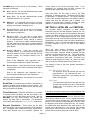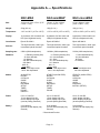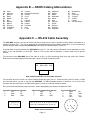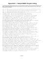
1
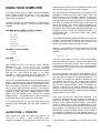
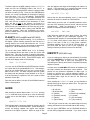
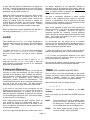
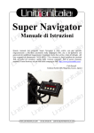
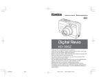
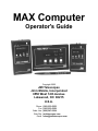
MAX Computer Operator's Guide Copyright 2005 JMI Telescopes Jim's Mobile, Incorporated 8550 West 14th Avenue Lakewood, CO 80215 U.S.A. Phone Fax Order Line Web Site Email (303) 233-5353 (303) 233-5359 (800) 247-0304 jmitelescopes.com [email protected] Table of Contents INTRODUCTION............................................................................................................. 4 What is Does................................................................................................... 4 What it Doesn't Do .......................................................................................... 4 GETTING STARTED ...................................................................................................... 4 Encoder Test........................................................................................................... 4 Troubleshooting ...................................................................................................... 5 USING YOUR COMPUTER ............................................................................................ 7 ALIGN STAR or STAR FIX...................................................................................... 7 RA DEC................................................................................................................... 8 CATALOG ............................................................................................................... 8 NEW Catalog .................................................................................................. 8 PLANETS........................................................................................................ 9 GUIDE..................................................................................................................... 9 IDENTIFY................................................................................................................ 9 ALIGN ................................................................................................................... 10 Subsequent Alignments ................................................................................ 10 TIMER ................................................................................................................... 10 ENCODER ............................................................................................................ 11 POLAR .................................................................................................................. 11 SETUP or INSTALL .............................................................................................. 11 About SET DEC=0, LEVEL ME, and VERTICAL .......................................... 12 Appendices A. Specifications ....................................................................................................... 13 B. NS/DS Catalog Abbreviations.............................................................................. 14 C. RS-232 Cable Assembly....................................................................................... 14 D. Sample BASIC Program Listing .......................................................................... 15 E. Quick-Start Guide ..................................................................................Back Cover INTRODUCTION accomplish this task. (Some "Go To" telescopes can be software controlled using the SGT-MAX system.) This manual covers the NGC-MAX, NGC-miniMAX and NGC-microMAX computer units. Sections which cover material not common to all of these units are labeled with the models they apply to. GETTING STARTED The MAX family of computers are revolutionary, computerized digital setting circle units with an internal database of hundreds to thousands of astronomical objects. After a simple alignment process (pointing your telescope at any two celestial objects, such as bright stars), the computer will operate as a high-resolution, real-time display of the Right Ascension and Declination of your telescope. Due to the internal database of galaxies, clusters, nebulae, stars, quasars, black holes and planets, the computer can quickly guide both the novice and expert viewer alike to almost any object desired. Instead of spending the majority of your viewing session attempting to locate objects, you can now be guided from object to object in seconds! The MAX computer utilizes an 8-character (16 on the NGCMAX) dot-matrix LED display with brightness control and four large push-buttons for the user-interface. All functions, including selection of any one of the internal objects, can be accomplished easily in a matter of seconds with very little practice. After a brief familiarization period, most users will be able to perform all operations by touch. The NGC-MAX's serial interface allows communication with external devices, opening the door to almost endless possibilities. One application of this technology is our popular SGT-MAX setup. This system allows users with a personal computer to install a real-time link between their telescope and desktop planetarium software, such as THESKY™ by Software Bisque. What it Does The MAX computer will guide the user to celestial objects by indicating the direction and angular separation for each axis of the telescope mount. When guiding to the Orion Nebula, the display might show the following: M042 59→ 51↑ To break this down, M042 represents Messier catalog number 42 (the designation for the Great Orion Nebula), 59→ indicates the object is 59° to the right, and 51↑ indicates the object is 51° up. As the telescope is moved in the directions indicated, these numbers will decrease toward zero, at which point the telescope is pointed at the desired object. What it Doesn't Do The MAX computer cannot physically move the telescope. The user will normally need to move the telescope by hand, although some telescopes have slewing motors which can Page 4 The first step in preparing to use your MAX computer is to install the optical encoders onto the axes of your telescope. If purchased with one or more sets of encoder mountings from JMI, will find a separate Encoder Installation sheet which covers the installation process required for your specific mount. Most of these installations require no drilling or tapping and can be installed in approximately 1520 minutes. After the encoders have been mounted, a test should be performed to confirm proper installation and function of each of the two encoders, as well as the setup information within the MAX computer. (When purchased with a set of encoder mountings, the MAX computer is pre-programmed with the necessary information to work with your specific mount, so you should not need to concern yourself with this aspect yet. For further information on this topic, see SETUP on page 11.) Encoder Test Plug the common end of the encoder cable into the MAX computer and each of the opposite two ends into its appropriate encoder (the Encoder Installation sheet indicates which end is for each encoder). Place the MAX computer unit in its holding tray or on a stable surface out of the way of the telescope's motion. The unit should be turned off at this time. Point your telescope at the zenith (directly overhead). Now turn the MAX computer on. After the version number is briefly shown, use the brightness button (found to the right of the ON/OFF switch) to set the display brightness as desired. Press the DOWN button until ENCODER is displayed, then press ENTER. The display should now show one of the following: NGC-MAX NGC-miniMAX/microMAX ER=000 ED=+000 000 +000 ER=000 ED=+090 000 +090 AZ=000 AL=+000 AZ=000 AL=+090 Note exactly where your telescope is pointed relative to your mount (mechanical setting circles make this easier), as you will want to be able to reliably return to this same position in a future step. Begin rotating your telescope in its Right Ascension or Azimuth axis (left-to-right) in a clockwise direction as seen from a vantage point directly above the telescope. (Southern Hemisphere users should rotate in the opposite direction.) The first set of displayed digits should increase as the telescope is moved (you will see something similar to 000 ... 001 ... 002 ... 003, etc.). If the digits decrease instead, see the troubleshooting guide for help. If possible, continue rotating the telescope through a full 360° circle. Verify the accuracy of the display by comparing it with the number of degrees you have moved in Right Ascension or Azimuth. At 360° you will see 359 or 0. Return the telescope to its starting point by rotating counterclockwise. At this point the digits should return to 000. If instead they vary from zero by more than plus or minus 1, see the troubleshooting guide for help. Now rotate the telescope in Declination or Altitude (up-and down) from the zenith toward the Southern horizon. The second set of digits should decrease (Note: an apparently increasing value is actually decreasing if the sign is negative). If the digits increase instead, then see the troubleshooting guide for help. If possible, continue rotating the telescope through a full circle. Return the telescope to its starting point by rotating in the opposite direction. At this point the digits should return to their original 000 or 090. If instead they vary from the original value by more than plus or minus 1, then see the troubleshooting guide for help. If you encountered no problems, continue on to the next section, USING YOUR COMPUTER. Troubleshooting Use the Troubleshooting Guide (below) to find possible causes then read the sections below for possible solutions. For a more in-depth troubleshooting guide, see the addendum Diagnosing MAX Computer System Problems. Low battery. The MAX computer can be powered from any 7-15 volt DC (direct current) source. When the power supply is below about 6.5 volts, the display will flash ENCODER ERROR. If using an internal 9 volt battery, be sure that it is alkaline ("Alkaline" must appear on the battery casing). Due to potentially rapid voltage and current drops in other battery designs, they should not be used. This includes nickelcadmium (NiCd) rechargeable batteries as well as carbonzinc batteries). Page 5 Troubleshooting Guide Symptom Possible Cause(s) The unit does not come on. • Low battery (use only alkaline batteries) The display does not reflect the motion of one or both encoders. • Mechanical slippage • Incorrect encoder setup • Bad encoder/cable One or both encoders • Reverse mounting appear to run in the opposite • Incorrect encoder setup direction. • "Hung" German mount Moving telescope in one axis changes opposite encoder reading. • Swapped encoder cables • Not polar aligned Bad warp factors, inaccurate • Incorrect encoder setup operation. • Incorrect initialization • Not polar aligned Display shows ENCODER ERROR at times. • Slew rate exceeded • Bad encoder/cable • Low battery Mechanical slippage. Verify that all appropriate setscrews and bolts are tight. Any gears or belts should not have slop (you should not be able to rotate the encoder shaft without turning the telescope — a belt does not need to be very tight to meet this criteria). You might want to mark the encoder shaft to determine if it rotates with the telescope as it should. Incorrect encoder setup. Since the computer can be used with various encoder resolutions and gearing ratios, the software allows the definition of the resolution for both axes. If this value is set improperly, the result can be slightly to grossly inaccurate performance, and if set to zero, can make an encoder appear to be non-functional. A separate sheet titled JMI Encoder Setup Sheet — TicsPer-Revolution, included with your encoder mountings, lists the correct setup to use with your specific mount. Confirm that the MAX computer setup matches this sheet paying particular attention to the order and sign of each tics-perrevolution specification (see SETUP on page 11 for additional help). Reverse mounting. If an encoder is running the improper direction, the simplest solution is to change the sign of that encoder's resolution as found in the setup (see SETUP on page 11). This should only become necessary if the encoder has been mounted in a manner contrary to that which was intended by the Encoder Installation sheet, or if the encoder installation is custom designed by the user. Alternatively, the encoder can sometimes be re-mounted so that it turns the opposite direction. Bad encoder/cable. While the probability of an encoder or cable being bad is extremely small, it is a possibility. If the problem is isolated to either the cable or encoder, there are a few simple tests which can quickly determine the exact culprit. Follow each point as outlined below, checking the operation of the encoders after each until the problem disappears. 1. Confirm that all three ends of the encoder cable are securely connected. If visible, inspect each of the four wires at the encoder pins to check for a loose or intermittent connection (it is normal for one of the second-to-outside pins to have no connection). 2. Swap the two encoder ends of the encoder cable so that the Right Ascension/Azimuth cable is plugged into the Declination/Altitude encoder and vice-versa. 3. If the symptom is still present on the same displayed axis after step 2, then the problem is in the encoder cable. Remove the cable from the problem axis and check the wire for damage and the cable's plug to see that all four golden metal plates have been pressed down evenly. If necessary, compare it with the other encoder plug. If one or more of these plates is high, you may try to press it down carefully with a small flat-head screwdriver or similar tool. If this cannot be done, the cable should be replaced. 4. If the symptom switches axes after step 2, then the problem is at the encoder. Remove the encoder cable connector and visually inspect the jack on the encoder. The four golden wires inside should be roughly even, although they might be staggered high-low-high-low. If any of the wires appears to be bent at an odd angle or pressed down too much, this could be the problem. The jack may need to be replaced. "Hung" German mount. (German equatorial mount users only). Because of the design of these mounts, it is possible to point the telescope at the same location from two quite different positions. To visualize this, point the telescope at 0° Declination. Now rotate the telescope 180° in each axis, avoiding the base as necessary. The telescope is on the opposite side of the mount head, yet pointing in the same direction. This feature of the German mount is nice when an object is located in a normally hard-to-view position, but it has the added affect of changing the polarity of the Declination encoder. For this reason, a unique stipulation is placed on users of German mounts — when performing the encoder test or an initial star alignment, the telescope tube must be on the West side of the mount. (Southern Hemisphere users should place the tube on the East side of their mount.) Refer to the addendum titled Star Alignments with a German Equatorial Mount for a complete description. Page 6 Swapped encoder cables. The Encoder Installation sheet included with the encoder mountings should detail exactly which encoder cable is for each axis. As a general rule, on equatorial mounts the Declination encoder cable is the longer of the two, and on Altitude/Azimuth mounts the Azimuth cable is longer. Not polar aligned. This is not a true problem as the MAX computer works very well even if the mount is 90° from polar aligned. However, there are symptoms of which the user should be aware. First, do not use the EP or GP mount setting unless your mount is accurately polar aligned, or you intend to use the POLAR mode to assist in polar alignment. Please note that the EP/GP settings assume a perfectly polar aligned mount — most pointing errors when using these settings are due to an inaccurate polar alignment. Second, a clock drive (Right Ascension motor) cannot properly track the stars if the telescope mount is not polar aligned — stars and other objects will appear to drift out of the eyepiece, requiring regular re-positioning. In other words, the closer your mount is to polar alignment the longer an object will stay in view without manual adjustments. Third (and the cause of misplaced concern among some new users of units such as the MAX computer), is the simultaneous change of both Right Ascension and Declination as seen under the RA DEC display when moving only one axis of the telescope. This is not an error as the MAX computer is simply reporting the telescope's true Right Ascension and Declination. What is commonly overlooked is the fact that a non-polar aligned mount is always moving through both Right Ascension and Declination when either of its two axes is rotated. Incorrect initialization. A common problem is that of ignoring or misunderstanding the initial pointing instruction from the MAX computer at power up (e.g. SET DEC=0, LEVEL ME, and VERTICAL). If you have set up the MAX computer for a polar aligned telescope (EP or GP), then you do not need to concern yourself with this aspect, although it might be a good idea to be familiar with it. See SETUP on page 11 for more information. Slew rate exceeded. The MAX computer has a maximum rate at which the encoders can be rotated. Due to the frequency at which the computer samples the encoders, they can be rotated faster than the computer can accept the data. The maximum speed depends on the number of tics per telescope axis rotation and the sampling rate. While it is unlikely that you will spin your telescope through a large arc fast enough to exceed this speed, it can be jolted a small amount in a very short interval causing a loss of alignment. With smaller telescopes and higher total encoder resolutions you will be more susceptible, but under normal operation you should never exceed the limit. USING YOUR COMPUTER alignment stars (chosen with the UP/DOWN buttons) and then center that star in your telescope's eyepiece. If you wish to start using your MAX computer immediately without reading through the manual, or you just want a quick refresher course, please refer to the Quick-Start Guide found in Appendix E. With the chosen star centered as well as possible in your telescope's eyepiece (not the finder scope), press the ENTER button to align the MAX computer on that star. Never use Polaris as an alignment star for an Equatorial mount and never use a star near Zenith for an Alt/Az mount. Any delay in pressing the ENTER button might allow the star to drift slightly from center, thereby decreasing the accuracy of your alignment — try to keep this delay as small as possible, with five seconds or less being about right. For increased accuracy during the alignment process, it is recommended that a short focal length (high power) eyepiece be used. The MAX computer has several modes, or applications to enhance your observing time. Below is a list of the modes available: NGC-MAX, NGC-miniMAX and NGC-microMAX ALIGN STAR or STAR FIX RA DEC CATALOG GUIDE ALIGN ENCODER SETUP or Install If you should accidentally press the ENTER button and align the MAX computer before you had the star centered in your eyepiece, you will need to reset the unit by turning it off, waiting five seconds, and then turning it back on. When you press ENTER for the first alignment, the MAX computer will briefly report a "warp" factor such as the following: NGC-MAX and NGC-miniMAX TIMER POLAR WARP=- 0.2 NGC-MAX IDENTIFY Upon turning the unit on, you will see a brief message, followed by ALIGN STAR or STAR FIX. (If instead you see a message to point the telescope a particular direction, you should do so if you plan to align the computer with the sky. See SETUP on page 11 for further information. When operating the unit apart from the telescope, you may simply press ENTER at this point.) Use the UP and DOWN buttons to scroll through the various modes. Notice that either of these buttons pressed for more than an instant will cause the options to scroll faster until the button is released. Following is a detailed description of each of these modes and how to use them. For reference, the UP and DOWN buttons scroll through options (whether choosing a mode, star name, catalog number or other option), and the ENTER button selects the currently displayed option. The MODE button is solely for returning to the mode level to permit selection of a new mode. It is recommended that the new user study each of the following mode descriptions with the MAX computer in hand. ALIGN STAR or STAR FIX Upon entering this mode, the display will read ALIGN ACHERNAR or similar. When connected to your telescope's encoders, you would need to select one of the Page 7 If you are using either of the EP or GP mount settings, which assume that the mount is perfectly polar aligned, the warp value will show zero and you will be ready to begin using the other features of the unit. If you are not using EP or GP (see SETUP on page 11) then you should finish this section before continuing. Since the telescope is not perfectly polar aligned (i.e. you are not using the EP or GP mode), you will need to align on one more star to complete the alignment procedure. For best results, the second star should be between 60° and 120° distance from the first star. Simply repeat the initial procedure of selecting a star name, pointing the scope to that star, then pressing ENTER. (Note: for simplicity, the method of aligning on two stars is presented here. In reality, the user may choose to align on any two objects in the MAX computer database, including the user definable objects, via the ALIGN mode.) Once again you will see a warp factor displayed. This message is reporting how many degrees the telescope is from where the MAX computer expected it to be when pointing at your selected alignment object. This number should be within plus or minus one-half degree of zero (±0.5). Any value greater than this should be considered an error indication. (It is possible to have a perfect warp factor and still have very poor pointing accuracy if one or both of the encoders is appearing to run the opposite direction. If this is experienced, see the Troubleshooting Guide on page 5.) If the warp factor is considerable, you should confirm that the star you are pointing at is indeed the one selected in the MAX computer. For indoor familiarization, the alignment process may be simulated to allow access to additional modes (attempting to select some modes before the alignment process has been completed will result in a STAR SIGHTINGS ARE REQUIRED message). RA DEC This mode displays the Right Ascension and Declination (coordinates) of the direction the telescope is currently pointed. By use of an internal sidereal clock, the MAX computer will work properly with or without a clock drive running. This means that users not using a clock drive will be able to watch the Right Ascension slowly increase with time as the Earth rotates. The Right Ascension is displayed in the format HHMM (hours and minutes) and the Declination is in the format ±DDTT (plus or minus degrees and tens of arc minutes). Please note that the Declination is to tens of minutes, not tenths of a degree (thus the digits 6-9 never appear in the last column). With the telescope pointed at R.A. (Right Ascension) 12 hours 36 minutes and Dec. (Declination) +26 degrees 42 minutes, the display would read: NGC-MAX: R=12h36 D=+26°42 miniMAX / microMAX: 1236+264 ST Unique compilation of most of the brighter and interesting stars (including many doubles) M Messier catalog (deep-sky) NGC Revised New General Catalog (deep-sky) IC Index Catalog (deep-sky) Planets Eight major planets and the Sun (alias "DATE") NEW User-definable list of object coordinates NS/DS Unique compilation of non-stellar, deep-sky objects. The user definable list contains the coordinates of any objects you wish, and can only be changed by writing new information over the old. In other words, even without a battery, the list is retained within the MAX computer until you want to change it. Upon entering the CATALOG mode, use the UP/DOWN buttons to select which catalog you wish to use, and then press ENTER. You will now be permitted to define the specific catalog number (2-4 digits, depending on the catalog) one digit at a time, or planet name. This is accomplished through a process similar to setting a digital watch. Use the UP/DOWN buttons to define each digit, then ENTER to continue on to the next. If your desired number is of fewer digits than requested, you will need to use preceding zeros (e.g. - for M1 you would enter M001). After ENTERing the last digit, the coordinates for that object will be displayed, similar to the following: M001 The MAX computer uses epoch 2000.0 coordinates. Because the computer "sees" all stars and objects relative to each other, rather than to an Earth-based coordinate system, the Earth's precession is not a factor in the pointing accuracy of the MAX computer. Only the reported R.A. and Dec. are affected by precession, therefore any user defined objects should be entered with epoch 2000.0 coordinates. The ENTER button can be pressed any time during the RA DEC mode to display a star chart number for that region of sky. The NGC-MAX can display information for either the Sky Atlas 2000.0 or Uranometria charts. The NGCminiMAX and NGC-microMAX units only display Sky Atlas 2000.0 chart numbers. 0534+220 With the exception of the planets and user defined (NEW) objects, you may now press ENTER once more to see a description of the object scroll across the screen. For our above example, this would appear as follows: M001 MAG= 8.4 SIZE=5.8 CRAB NEBULA SUPERNOVA REMNANT TAURUS NEBULA SA=05 The descriptions fit a common format which is normally selfexplanatory. This format is: object catalog and number; magnitude; size (in minutes unless followed by "); common name (if applicable); constellation; object type; and Sky Atlas 2000.0 or Uranometria chart number. The smaller NGC-microMAX database does not include size, constellation or type information. NEW Catalog CATALOG The MAX computers have several catalogs in memory: Model ST M NGC IC P NEW NS/DS NGC-microMAX 90 110 NGC-miniMAX 80 110 2745 960 9 NGC-MAX 928 110 7840 2852 9 28 28 28 17 86 386 Page 8 The coordinates for up to 28 user defined objects may be entered into the MAX computer for later reference. This can be used to store the positions of objects not found in the other MAX computer catalogs (such as comets, asteroids and variable stars). While it is possible to plan an evening's viewing ahead of time and put the coordinates of each object in the NEW catalog, it is recommended that the builtin catalogs (M, NGC, etc.) be used whenever possible. This is because the built-in catalogs store coordinates more precisely than is allowable under the NEW catalog. To add an object to the NEW catalog, enter the CATALOG mode and use the UP/DOWN buttons until NEW01 is displayed. After pressing ENTER, select the object number you wish to modify (01-28). Once you have ENTERed the number, the current coordinates are displayed (if defining for the first time, 2400-000 will appear). Press ENTER once more and the first digit of the Right Ascension will begin flashing. Define the new coordinates one digit at a time, until the last is entered (if the Declination is three digits, the last is tens of arc minutes, not tenths of a degree). The display will stop flashing, and at this point you should review your coordinates to be sure they are correct. If you need to change them, simply press ENTER and repeat the process. When the coordinates are correct, press the MODE button to have the MAX computer store them in its memory. PLANETS (NGC-miniMAX and NGC-MAX) Upon ENTERing the PLANETS catalog, DATE will flash on the display. Before selecting a planet for the first time in a viewing session, the current date should be set. For the most accurate guiding, use the current date for Greenwich, England (i.e. set the date based on Universal Time). To set the date, press ENTER while DATE is flashing. (The coordinates shown are those of the Sun for the last defined date. This may be useful for daytime alignments, however, you should take proper precautions when pointing your telescope near the Sun!) Press ENTER again, and you will see a display similar to the following: DATE 12-31-2000 You may use the UP/DOWN and ENTER buttons to define the current date in the format MM-DD-YYYY. This setting is stored in non-volatile RAM, so if the unit is turned off the date will not be lost. The MAX computer does not update this setting with the passage of time (whether on or off), so it will be necessary to update it if the unit is used to locate planets at a later date. Once the date is defined, use the UP and DOWN buttons to select a desired planet. GUIDE After selecting a desired object under CATALOG, entering GUIDE mode will show you how far to move the telescope in each axis to find that object. Following is an example display: NGC4565 171← 29↓ This indicates that the telescope should be moved to the left 171° and down 29° to locate NGC4565. As the telescope is moved, the display updates the angles and changes directions if the object is passed. When an angle is less Page 9 than ten degrees, that angle will be displayed to tenths of a degree. If the telescope in our example had been moved down 21.7 degrees, the display would now read: NGC4565 171← 6↓3 Notice that the direction-indicating arrow (↓) has moved between the 6 and 3 to double as a decimal point. While entirely up to the user, it is probably easiest to move one axis of the telescope mount at a time, rather than both simultaneously. When the telescope is at the correct position, the display will show the following: NGC4565 0♦0 0♦0 If the initial star sighting(s) were done properly, the object should now appear in your telescope's eyepiece. A moderate power eyepiece is recommended when using the GUIDE mode, as the object is more likely to be within its field of view than in that of a high power eyepiece. Eyepieces yielding 1/4° to 1/2° field of view work best. (If you don't know the field of view of your eyepieces, try finding one which just fits the full moon into the field.) IDENTIFY (NGC-MAX only) If you are looking at an object you cannot identify, this mode will let the NGC-MAX try to identify it for you. Additionally, you might simply wish to point your telescope to an unfamiliar part of the sky and have the computer find nearby objects of interest. In either case, the NGC-MAX will search its databases for the object nearest the telescope's current position. The search can be performed regardless of object type, or limited to a specific type, such as planetary nebulae. A limiting magnitude is also entered to eliminate objects from the search which might be too faint for the observer's circumstances. Upon entering the IDENTIFY mode, you are allowed to specify which type of object you wish to find. This type can be any of the following: R (red star) 2 (double star) NB (nebula) PN (planetary nebula) GX (galaxy) OC (open cluster) GC (globular cluster) ST (star) BK (black hole candidate) QSR (quasar) NS (any non-stellar)* ANY (any of above) * The NS type is used to find a non-stellar object from any catalog, and should not be confused with the NS catalog. After the type is ENTERed, use the UP/DOWN buttons to set the limiting magnitude as desired. If you enter a value of eight, then only objects of magnitude 8.0 or brighter will be found. The limiting magnitude range is from one (bright) to 17 (faint). Those objects which do not have a magnitude defined are only found with a limit of 17. When both search parameters have been defined, press ENTER and the computer will display the name of the nearest object meeting your search criteria. Because the display is updated every few seconds to indicate the nearest object at that instant, you may move the telescope until an object you wish to observe is shown. Pressing ENTER will scroll the information available on the object. the angular separation of the alignment positions is essentially equal to the separation of the objects. Note the distinction between alignments and objects. Relative to the Earth, an object's position is changing with time, however the alignment positions remain fixed. Any time a subsequent alignment is made, pointing accuracy in the neighboring region should be improved. However, it is possible for such an alignment to decrease pointing accuracy elsewhere, even to an extent worse than that observed prior to the new alignment. ALIGN When a new alignment is made, one of the previous two alignment positions — that which is least desirable relative to the new — is discarded. Therefore, the angle of separation between the remaining previous alignment position and that of the new alignment becomes the critical factor. If this angle is too small or too great, the overall pointing accuracy will degrade. This is similar to the ALIGN STAR mode, except that an alignment may be done on any object in the MAX computer catalogs. This includes the planets and user defined objects. For the average user, this should not be a noticeable problem, but if you should experience degraded accuracy, it can probably be eliminated by following these steps in selecting subsequent alignment objects: The object used for the ALIGN mode is that last displayed in the ALIGN STAR, CATALOG or IDENTIFY modes. Use one of these modes if you wish to select a different object. 1. Recall the positions of your last two alignment objects, relative to the Earth (these are not their current positions). When no object fits the search parameters, the first item in the catalog is displayed (e.g. FOUND NGC0001). The ALIGN mode can be used in place of, or in conjunction with the ALIGN STAR mode to meet the initial alignment requirements, as well as for subsequent alignments, as outlined below. Subsequent Alignments If, in the course of an evening's viewing, you find that the accuracy of guiding has decreased, you may re-align the telescope on an additional object to restore this accuracy. Such a situation is normally caused by inaccuracies in the manufacture of the telescope's mount, affecting its orthogonality (meaning all axes are perpendicular). This introduces a pointing error when moving the telescope from one side of the sky to the other. The MAX computer assumes a perfectly orthogonal mount for its calculations. If your mount is very close to being orthogonal, you will probably never see such an error, and should not need to make additional alignments. If, however, you do wish to make an alignment subsequent to the initial two required, you should keep the following in mind. (This does not apply to users of the EP or GP settings.) When making alignments, the MAX computer "sees" all such locations in terms of an Earth-based reference. In other words, the altitude and azimuth of an object, at the time of its alignment, determines its angular separation from another alignment object. Of course, if alignments are done near to each other in time, Page 10 2. Try to make your subsequent alignment on an object which is as close to 90° (±30°) from either one of your last two alignment positions as possible. This process will maintain maximum pointing accuracy and should be followed with each subsequent alignment. TIMER (NGC-miniMAX and NGC-MAX) This is a 24 hour event timer which displays to the second. Possible uses for this mode include recording elapsed time between occultation contacts or other astronomical phenomena, and exposure times for astrophotography. Upon entering this mode, the display will read: 00 00 00.0 (Tenths of a second are not displayed on the NGCminiMAX.) While in this mode, use the MODE and ENTER buttons as follows: MODE This will exit the timer mode, permitting another mode to be chosen. The timer will continue in the background, so that returning to this mode will accurately show the current elapsed time. ENTER This button cycles through a series of three functions: START, STOP, and RESET. The timer is started by pressing the ENTER button, which will temporarily cause the display to show the following: START The elapsed time from the moment you pressed the ENTER button will then be displayed until you press ENTER to stop the timer or MODE to exit the timer mode. ENCODER This mode is primarily used for verifying proper operation of the encoders. The encoder angles (in whole degrees) relative to their startup positions is shown. For equatorial mounts, the first axis is Right Ascension and the second Declination; for Alt/Az mounts, the first axis is Azimuth, the second Altitude. For more information on using this mode to test the performance of your encoders, see the Encoder Test section beginning on page 4. POLAR (NGC-miniMAX and NGC-MAX) Although the MAX computer can be used without it, having your telescope polar aligned is desirable in many cases. The accuracy of a clock drive depends upon this alignment for visual and especially photographic purposes. The POLAR mode is used to achieve a highly accurate polar alignment. Before using this mode, you must change your setup to reflect either an EP (Equatorial - Polar aligned), or GP (German - Polar aligned) mount. See SETUP, below, for help on doing this. If you do not do so, upon attempting to enter this mode nothing will happen or you will see: ONLY FOR EP GP Once you have ENTERed the POLAR ALIGN mode, use the UP and DOWN buttons to choose a reference star by name from the list of 30 to 40. The star you choose should be between 60º and 120º from the pole — with those near the celestial equator being best. Do not press any more buttons yet. With your mount at least roughly on the pole (the closer you are to begin with, the faster the process), point the telescope at your chosen star and press ENTER once it is in the center of your eyepiece. A bright asterisk (*) may momentarily appear, followed by a display similar to the following: POLARIS 77← 83↓ Page 11 This indicates the direction and distance to Polaris. You should now move your telescope to the indicated position just like under GUIDE mode. When you have zeroed both angles, your display should look like this: POLARIS 0♦0 0♦0 If your mount is polar aligned, Polaris will appear near the center of a moderately powered eyepiece. (Don't worry about the offset of Polaris from the actual pole — the MAX computer is accounting for this.*) If Polaris is not near the center of your eyepiece, you will need to adjust the altitude and azimuth adjustments of your mount until Polaris is centered in your eyepiece. Be sure not to move your telescope relative to your mount — the computer's display should remain as shown above. If you should accidentally move the telescope itself, you can zero the angles again so that the display does match that above. Now press the ENTER button, and you will briefly see a reminder to adjust your altitude and azimuth, then a display similar to this: SIGHT PROCYON You should now point your telescope back at your reference star and center it in the eyepiece. Press ENTER and you will be instructed to guide back to Polaris. Repeat the above process from this point as many times as desired. With each iteration of the process, your telescope's polar alignment should become more and more accurate. Two or three iterations should be sufficient for most visual work, while up to five or six iterations may be required for longexposure photographic work. Users installing a mount permanently will find this procedure helpful for obtaining an accurate polar alignment, however one of the more time-consuming methods (star drift or photographic) should be used for fine tuning. * While your telescope's optical tube is being aligned on Polaris, the mount's polar axis is actually being aligned on the pole, not Polaris. SETUP or INSTALL This mode is used characteristics of your setup parameters is showing the selected following: to tell the MAX computer some mount. The meaning of each of the defined here. The first display, mount type, will be similar to the SCOPE EQ Mount. This setting informs the MAX computer of the type of mount your telescope is on. The six types to choose from are AZ, AV, EQ, EP, GQ, and GP (the NGC- microMAX does not have the EP or GP settings). These represent the following: AV Alt/az Vertical. For use with altitude/azimuth mounts initialized to a vertical* position. AZ Alt/az Zero. For use with altitude/azimuth mounts initialized to a level* (or 0°) position. EQ EQuatorial. For equatorial mounts using a two-star alignment. This must be used if you have a non-polar aligned, non-German, equatorial mount. EP Equatorial Perfect. Only for use with a non-German, equatorial mount which will be used in a perfectly polar aligned configuration. ET Equatorial Table. For use with a mount whose tracking motion is not apparent to the encoders (such as an altitude/azimuth mount utilizing a tracking platform). In this mode, the MAX computer assumes that the telescope is being driven at exactly sidereal rate, however it does not require that the mount be polar aligned. GQ German EQuatorial. Used with non-fork type equatorial mounts. If the telescope can be pointed in the same direction from two unique positions (as with German mounts), the computer assumes one of these positions. Refer to the addendum "Star Alignments with a German Equatorial Mount" for further information. GP German Perfect. Used with non-fork type equatorial mounts which will be used in a perfectly polar aligned configuration. Refer to the addendum Star Alignments with a German Equatorial Mount for further information. * See the separate addendum The Importance of the Initial NGC Alignment for details. Scroll Rate. This determines how fast the information on objects is scrolled across the MAX computer display. The default value (that set prior to shipment) is 5, with the range being 0 (slowest) to 9 (fastest). Chart Reference. Whenever information on an object is scrolled across the display, the last item shown is the chart number on which that object can be found. With the NGC-MAX you may select between two popular star atlases: Sky Atlas 2000 or Uranometria. The appropriate chart number will appear after "SA=" or "UA=" respectively. Encoder Resolution. These values tell the MAX computer what the final output resolutions of the encoders are. A separate sheet, JMI Encoder Setup Specifications, which was included with your encoders, specifies the Page 12 correct values to use for your telescope mount. If you purchased your encoders with the MAX computer, the resolutions are already defined for your mount. Under this setup, the first value is that of the Right Ascension, or Azimuth encoder. The second value is that of the Declination, or Altitude encoder. The correct resolution is that of the encoder multiplied by the number of turns it makes each time the telescope axis is rotated. For example, an encoder with a resolution of 5000 tics, when geared 2:1, yields an effective resolution of 10000. SET DEC=0, LEVEL ME, and VERTICAL For non-polar aligned telescopes, or polar aligned telescopes using the two-star alignment method, the only case in which you can ignore the initial pointing instruction is when the MAX computer will not be used for actual viewing (such as when conducting the Encoder Test). At all other times, this step is vital to proper performance, and can greatly affect the accuracy of the unit (either beneficially or detrimentally). None of the above messages will appear if the MAX computer is set for use with a polar aligned telescope. When the initial pointing instruction is displayed (immediately after the power-up version message), no button on the MAX computer should be pressed until that positional requirement has been met. This initial position tells the computer where your two encoder axes are perpendicular (or parallel) to each other. This point is not affected by polar aligning or leveling, so it does not matter how your mount is oriented relative to the Earth or sky. The meaning of each of the three possible messages is outlined here: SET DEC=0 or LEVEL ME The telescope should be pointed with the tube perpendicular to the polar/azimuth axis. A Declination setting circle, if set properly, may be used to find this point. VERTICAL The telescope should be pointed with the tube parallel to the polar/azimuth axis. A Declination setting circle, if set properly, may be used to find this point. It should be noted that improving this initial alignment can greatly increase the guiding accuracy without showing an improvement in the warp factor (which only measures the accuracy of the distance between the two alignment stars). Since factory marks are often off by a significant amount, you may wish to do the following test. First, adjust the initial position in one direction a few thousandths of an inch, finish the alignment, then test the guiding accuracy. If it is worse, try adjusting the initial alignment in the other direction. Do several more adjustments in the direction that showed improvement until you see the most accurate guiding. This process is time consuming but well worth the effort. Appendix A — Specifications NGC-MAX NGC-miniMAX* NGC-microMAX Size: 14.6cm x 9.1cm x 3.7cm (5.75" x 3.60" x 1.44") 7.0cm x 11.7cm x 3.0cm (2.75" x 4.60" x 1.18") 6.1cm x 9.9cm x 3.0cm (2.40" x 3.88" x 1.18") Weight: 233g (8.2 oz.) 155g (5.4 oz.) 122g (4.3 oz.) Temperature: -10°C to +50°C (14°F to 122°F) -10°C to +50°C (14°F to 122°F) -10°C to +50°C (14°F to 122°F) Display: 16 character, 5x5 dot matrix red LED (four brightness levels) 8 character, 5x5 dot matrix red LED (four brightness levels) 8 character, 5x5 dot matrix red LED (four brightness levels) Coordinates: Epoch AD 2000.0 Epoch AD 2000.0 Epoch AD 2000.0 Sensors: Two high-resolution, shaft- type, incremental optical encoders Two high-resolution, shaft- type, incremental optical encoders Two high-resolution, shaft- type, incremental optical encoders Sampling rate: 2.5KHz (2500 samples/sec) 1.95KHz (1950 samples/sec) 2.5KHz (2500 samples/sec) Database: 9 28 110 386 928 2852 7840 12153 12047 Planets (including Sun) User definable Messier Non-stellar/deep-sky Stars IC NGC Total object count Non-duplicated 9 28 80 86 110 960 2745 4018 3912 Planets (including Sun) User definable Stars Non-stellar/deep-sky Messier IC NGC Total object count Non-duplicated 17 28 90 110 Non-stellar/deep-sky User definable Stars Messier 245 Total object count 245 Non-duplicated Modes: ALIGN STAR RA DEC CATALOG GUIDE ALIGN ENCODER SETUP TIMER POLAR IDENTIFY STAR FIX (ALIGN STAR) RA DEC CATALOG GUIDE ALIGN ENCODER SETUP TIMER POLAR STAR FIX (ALIGN STAR) RA DEC CATALOG GUIDE ALIGN ENCODER INSTALL (SETUP) Power: 6.5 to 15 volts DC 17mA, display fully dim 60mA, display fully bright (reverse polarity protected) 6.5 to 15 volts DC 17mA, display fully dim 45mA, display fully bright (reverse polarity protected) 6.5 to 15 volts DC 14mA, display fully dim 44mA, display fully bright (reverse polarity protected) Battery: 9 volt alkaline (25 hour life with display fully dimmed) 9 volt alkaline (25 hour life with display fully dimmed) 9 volt alkaline (30 hour life with display fully dimmed) * Discontinued Product Page 13 Appendix B — NS/DS Catalog Abbreviations AB AN B BA BD BI BK BL BO CE CR Abell Antalova Barnard Basel Baade Biur Berkley Blanco Bochum Cederblad Colinder CZ DD DO FR GU H HA HB HU KI LY MA ME MF MK MR NE PA PI RO RU SH2 Czernik Dolidze-Dzimselejsvili Dolidze Frolov Gum Harvard Haffner Hubble Humason King Lynza Markarian Melotte Maffei Minkowski Merrill New Palomar Pismis Roslund Ruprecht Sharpless SP ST TO TR TZ U VB Stephenson Stock Tombaugh Trumpler Terzian Upsala Van Den Burgh Appendix C — RS-232 Cable Assembly The NGC-MAX computer unit has an RS-232 serial port which may be used to provide encoder position information to a personal computer (PC). This can be used with the sample BASIC program provided in Appendix D, or with a commercial software program which supports the NGC-MAX protocol (such as Software Bisque's THESKY™). A special cable is required between the NGC-MAX and your PC. You may use the information here to assemble your own cable, or you may purchase one from JMI. While a 12 foot (3.6m) cable is standard, a custom length may be special ordered. The connector at the NGC-MAX side of the cable is an RJ11 or RJ12 phone-type plug using the center four contacts. Reference the following diagram when inserting the wires from a flat 4-conductor cable: YEL GRN RED BLK Wire insertion end of RJ11 or RJ12 male connector The connector at the PC can be one of three varieties, depending upon your PC. Check the size of the PC's serial, or COM port connector which you plan to use with the NGC-MAX. On IBM-compatible systems, it should be a 9 or 25 pin male connector with two rows of pins. On Macintosh systems, it will be a round 8 pin female connector. Once you have determined the proper connector, use the appropriate pinout below to complete the cable. 9-socket D-subminiature (female) 2 YEL TX 3 GRN RX 5 RED GND 1 2 3 4 5 6 7 8 9 25-socket D-subminiature (female) 2 GRN RX 3 YEL TX 7 RED GND 1 2 3 4 5 6 7 8 9 10 11 12 13 14 15 16 17 18 29 20 21 22 23 24 25 Solder side of connectors Page 14 8-pin mini-DIN (male) 3 GRN 4 RED 5 YEL 8 RED 1 3 6 2 4 7 5 8 RX GRN TX GND Appendix D — Sample BASIC Program Listing The following program listing has been tested on numerous MS-DOS compatible computers using both GW-BASIC and QBASIC. While all efforts have been made to ensure error-free code, the user is solely responsible for the accurate entry and operation of this program. 100 110 120 130 140 150 160 170 180 190 200 210 220 230 240 250 260 270 280 290 300 310 320 330 340 350 360 370 380 390 400 410 420 430 440 450 460 470 480 490 500 510 520 530 540 550 '*************************************************************************** '** This BASIC program reads and displays encoder positions directly ** '** from the RS-232C serial port of the JMI NGC-MAX v3.50 or later ** '** Copyright 1996-2005 by Jim's Mobile Inc. ** '*************************************************************************** ENC(1)=4096: 'Defines telescope Azm/RA encoder resolution ENC(0)=4000: 'Defines telescope Alt/DEC encoder resolution PORT$="COM1": 'Defines which serial port is connected to the NGC-MAX CLS:PRINT "Make sure the NGC-MAX is on - then press the SPACE bar." K$=INKEY$:IF K$="" THEN GOTO 190: 'Waits for user to press a key IF K$=CHR$(27) THEN GOTO 370: 'If ESC is pressed, jumps to line 370 OPEN PORT$+":9600,N,8,1,RS,CS,DS" AS #3: 'Opens serial port DEFP$="+00000"+CHR$(9)+"+00000": 'Defines the default position response P$="":PRINT #3,"Q";: 'Asks NGC-MAX for encoder positions K$=INKEY$:INPUT #3,P$: 'Reads keyboard/serial port IF K$ = CHR$(27) THEN GOTO 370: 'If ESC is pressed, jumps to line 370 IF P$="" THEN GOTO 230: 'Waits for input from keyboard or serial port IF LEN(P$)<8 THEN P$=DEFP$: 'If input not complete, sets to default AZM$=LEFT$(P$,6): 'Extracts the Azimuth/R.A. encoder position ALT$=MID$(P$,8,6): 'Extracts the Altitude/Dec. encoder position A=-VAL(AZM$):GOSUB 400: 'Jumps to line 400 to interpret Azimuth angle RA$=A$: 'Sets variable RA$ equal to the Azimuth angle A=VAL(ALT$):GOSUB 400: 'Jumps to line 400 to interpret Altitude angle DEC$=A$: 'Sets variable DEC$ equal to the Altitude angle LOCATE 10,19:PRINT "Azm/R.A.= ";RA$: 'Displays the Azimuth/R.A. angle LOCATE 10,46:PRINT "Alt/DEC.= ";DEC$: 'Displays the Altitude/Dec. angle GOTO 230: 'Goes back to line 230 to check positions again CLOSE #3:LOCATE 20:PRINT "Exiting program.": 'Closes the serial port SYSTEM: 'and EXITS the program '*** This subroutine changes the raw encoder data into angular form. *** AX=(AX=0): 'Toggles variable AX to indicate which axis A=A*360/ENC(-AX): 'Changes raw encoder tic value to an angle IF A>359 THEN A=A-360:GOTO 420: 'Makes sure angle is less than 360 IF A<-359 THEN A=A+360:GOTO 430: 'Makes sure angle is greater than -360 IF NOT AX AND A>180 THEN A=A-360: 'Makes sure Altitude is within -180 to 180 IF A<0 AND AX THEN A=360+A: 'Makes sure Azimuth is greater than zero A=A+.0051:A=INT(A*10000)/10000: 'Puts angle in a 2 decimal place format S=SGN(A):A$="000"+MID$(STR$(A),2): 'Temporarily adds leading zeros A=0:FOR X=1 TO LEN(A$): 'Starts looking for decimal place in angle IF MID$(A$,X,1)="." THEN A=X: 'When decimal found, marks with variable A NEXT X:IF A=0 THEN A$=A$+".0":A=LEN(A$)-2: 'Adds decimal value if absent A$=MID$(A$,A-3,6): 'Extracts the angle in proper format IF LEN(A$)<6 THEN A$=A$+"0": 'Makes sure second decimal place is present S$="+":IF S<0 THEN S$="-": 'Sets the sign as plus or minus for angle IF NOT AX THEN A$ = S$ + A$: 'Adds sign to the Altitude angle only RETURN: 'Returns the program to line 310 or 330 Page 15 Appendix E — MAX Quick-Start Guide NOTE: For best results, the following steps should be followed while using the telescope under actual observing conditions. Simulated star alignments may be used for the purpose of familiarizing yourself with the operation of the computer, however, the user should be aware that under these conditions the coordinate display and GUIDE mode will behave unpredictably. 1. Turn unit ON. A message will appear briefly. 2. Use the DIM button to set the brightness of the LED display as desired. If at any time during these steps a single, bright asterisk (*) is shown on your display, it is an indication of an encoder error. It can also be indicated by the display showing ENCODER ERROR. This can be caused by turning the telescope too rapidly or a bad electrical connection (including not having the encoders plugged in). 3. If display shows: Then do this: DEC=0 Point your telescope such that the Declination setting circle is at the zero degree mark*. Press the ENTER button and proceed to step 4. MODE ALIGN STAR The computer is set up for polar alignment. If the telescope is not polar aligned, or STAR FIX the POLAR ALIGN mode may be used as an aid to this end. Proceed to step 4. VERTICAL (Used with Altitude/Azimuth mounts) Position the telescope tube such that it is pointed directly perpendicular to the bottom of the rocker box*. Press the ENTER button and proceed to step 4. LEVEL ME (Used with Altitude/Azimuth mounts) Position the telescope tube such that it is pointed exactly parallel with the bottom of the rocker box*. Press the ENTER button and proceed to step 4. * This initial setting needs to be as accurate as possible. The maximum tolerable error is one half of a degree. Any error larger than this will result in poor pointing accuracy. Please see the addendum The Importance of the Initial NGC Alignment for additional help on this setting. 4. Choose a bright star to use as an initial alignment. (Do not use Polaris with an Equatorial mount or a star at Zenith with an Alt/Az mount.) After entering ALIGN STAR or STAR FIX mode (by pressing ENTER when this is shown on the LED display), use the UP and DOWN buttons to scroll through the star list until your chosen star's name is displayed. 5. With the star from step 4 centered in your telescope's eyepiece, press the ENTER button to align on the star. If a W or WARP value is shown, it may be ignored at this point (only the warps on alignments after the first have real meaning). 6. Repeat steps 4 and 5 using a second star which is at least 60 degrees from the first to complete the alignment procedure (Polaris may be used for this alignment). At this point the warp value should be ±0.50 or less for accurate alignment. 7. To view an object, press the MODE button to enter the mode selection, and use the UP and DOWN buttons to locate the CATALOG mode (this is two presses of the UP button from ALIGN STAR or STAR FIX). 8. Press the ENTER button to select CATALOG mode. If you followed the above steps properly, the display will now show a flashing ST next to a three digit number. This is indicating that you are currently working with the STar catalog, the number being that of the alignment star from step 5. 9. To select an object, you must first define which catalog it is in. Use the UP and DOWN buttons to set the catalog (ST=STARS, M=Messier, NGC=New General Catalog, IC=Index Catalog, NEW=User definable objects), then press ENTER. 10. You will now see the first digit of a 2-4 digit number flashing. Use the UP and DOWN buttons to select the first digit of the catalog number you wish to observe. (If your catalog number is of fewer digits than that displayed, you must use preceding zeros. For example, to enter M-42, your display would look like this: M042.) 11. With the first digit set, press ENTER and the second digit will be flashing. Continue this process until you have all digits set as needed. Pressing ENTER once more will display the Right Ascension and Declination for that object. 12. If you would like to see the information which the MAX has on this object, press ENTER again. The display will scroll the catalog number, magnitude, (size, common name, constellation), type of object, and Sky Atlas (SA) or Uranometria (UA) chart reference. 13. Press the MODE button to return to mode selection. Press the UP button then ENTER to select GUIDE mode. 14. Displayed is the angular distance and direction to that object from the telescope's current location. The first angle is that of Right Ascension/Azimuth, and has a left or right facing arrow to indicate direction. The second angle is that of Declination/Altitude, and has an up or down facing arrow to indicate direction. 15. Moving the telescope in the direction indicated (one axis at a time if desired), the angles will decrease toward zero. Whenever an angle is less than ten degrees, that angle is shown to tenths of a degree with the arrow doubling as a decimal point. Zeroing both angles results in pointing the telescope at the selected object. JMI Telescopes Jim's Mobile, Inc. y 8550 W 14th Ave y Lakewood, CO 80215 y USA y 303-233-5353 y Fax 303-233-5359 y jmitelescopes.com