1
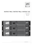
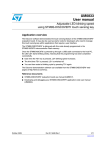
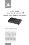
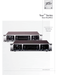
OWNER’S MANUAL four-channel system amplifier Thank you for purchasing a JL Audio amplifier for your automotive sound system. Your amplifier has been designed and manufactured to exacting standards in order to ensure years of musical enjoyment in your vehicle. For maximum performance and extended warranty coverage, we highly recommend that you have your new amplifier installed by an authorized JL Audio dealer. Your authorized dealer has the training, expertise and installation equipment to ensure optimum performance from this product. Should you decide to install the amplifier yourself, please take the time to read this manual thoroughly so as to familiarize yourself with its installation requirements and setup procedures. If you have any questions regarding the instructions in this manual or any aspect of your amplifier’s operation, please contact your authorized JL Audio dealer for assistance. If you need further assistance, please call the JL Audio Technical Support Department at (954) 443-1100 during business hours. PROTECT YOUR HEARING! We value you as a long-term customer. For that reason, we urge you to practice restraint in the operation of this product so as not to damage your hearing and that of others in your vehicle. Studies have shown that continuous exposure to high sound pressure levels can lead to permanent (irreparable) hearing loss. This and all other high-power amplifiers are capable of producing such high sound pressure levels when connected to a speaker system. Please limit your continuous exposure to high volume levels. While driving, operate your audio system in a manner that still allows you to hear necessary noises to operate your vehicle safely (horns, sirens, etc.). SERIAL NUMBER In the event that your amplifier requires service or is ever stolen, you will need to have a record of the product’s serial number. Please take the time to enter that number in the space provided below. The serial number can be found on the bottom panel of the amplifier and on the amplifier packaging. INSTALLATION APPLICATIONS This amplifier is designed for operation in vehicles with 12V, negative-ground electrical systems. Use of this product in vehicles with positive ground and/or voltages other than 12V may result in damage to the product and will void the warranty. This product is not certified or approved for use in aircraft. %POPUBUUFNQUUPiCSJEHFwUIFPVUQVUTPGUIJT amplifier with the outputs of a second amplifier, including an identical one. Cooling Efficiency Considerations: Your JL Audio amplifier employs an advanced type of heat management, called RealSink™. This feature takes advantage of convection and radiation effects to remove heat from the amplifier circuitry. For optimum cooling performance, the vertical heat sinks located at the back of the amplifier should be exposed to as large a volume of air as possible. Enclosing the amplifier in a small, poorly ventilated chamber can lead to excessive heat build-up and degraded performance. If an installation calls for an enclosure around the amplifier, we recommend that this enclosure be ventilated with the aid of a fan. In normal applications, fan-cooling is not necessary, but you still need to follow some basic guidelines: t"NQMJGJFSNPVOUFEWFSUJDBMMZXJUIIFBUTJOLGJOT pointing up: Optimum t"NQMJGJFSNPVOUFEIPSJ[POUBMMZ right side up: Good t"NQMJGJFSNPVOUFEIPSJ[POUBMMZCVUVQTJEF down: Fair (not recommended if there is less than 1 inch (2.5 cm) clearance above the amplifier heat sinks) t"NQMJGJFSNPVOUFEWFSUJDBMMZXJUIIFBUTJOLGJOT pointing laterally: Fair t"NQMJGJFSNPVOUFEWFSUJDBMMZXJUIIFBUTJOLGJOT pointing down: Poor (not recommended) PLANNING YOUR INSTALLATION It is important that you take the time to read this manual and that you plan out your installation carefully. The following are some considerations that you must take into account when planning your installation. Serial Number: Chassis Ground Connector (pg. 6) +12 V Power Remote Turn-On Connector Connector (pg. 6) (pg. 7) +12VDC Ground Remote Safety Considerations: Your amplifier needs to be installed in a dry, well-ventilated environment and in a manner which does not interfere with your vehicle’s safety equipment (air bags, seat belt systems, ABS brake systems, etc.). You should also take the time to securely mount the amplifier using appropriate hardware so that it does not come loose in the event of a collision or a sudden jolt to the vehicle. Stupid Mistakes to Avoid: tCheck before drilling any holes in your vehicle to make sure that you will not be drilling through a gas tank, brake line, wiring harness or other vital vehicle system. t%POPUSVOTZTUFNXJSJOHPVUTJEFPSVOEFSOFBUI the vehicle. This is an extremely dangerous practice which can result in severe damage to your vehicle and person. t1SPUFDUBMMTZTUFNXJSFTGSPNTIBSQNFUBM edges and wear by carefully routing them, tying them down and using grommets and loom where appropriate. t%POPUNPVOUUIFBNQMJGJFSJOUIFFOHJOF compartment, under the vehicle, on the roof or in any other area that will expose the amplifier circuitry to the elements. CH 3&4 HP Filter Slope Selection / Defeat (pg. 9) CH 3&4 CH 1&2 CH 1&2 Input Filter Slope Sensitivity Control Selection / Defeat (pg. 8) (pg. 9) CH 1&2 CH 1&2 Filter Frequency Input Voltage Range Selector Range Selector (pg. 9) (pg. 7) Infrasonic Filter On/Off Switch (pg. 11) Preamp Output Signal Selector (pg. 10) CH 1&2 Speaker Outputs (pg. 11) Preamp Output Section CH 1 & 2 Speaker Outputs Bass EQ On/Off Switch (pg. 11) CH 1 & 2 Bass Control Signal From Bass EQ Infrasonic Filter 1 & 2 | 3 & 4 | All Off | On Off | 30Hz 450 /4v2 Left Four-Channel System Amplifier Left Output Right Output Left and Right Preamp Output Jacks (pg. 10) 2 | JL Audio - 450/4v2 Owner’s Manual If mounting the amplifier under a seat, make sure there is at least 1 inch (2.5 cm) of space above the amplifier’s outer shell to permit proper cooling. Either feature sums the CH 1&2 input signals to mono when activated. Right Bridged: 300W x 1 (3-8Ω) Remote Bass Port Jack for Remote Bass Control Knob (pg. 11) CH 1 & 2 Filter Section Freq. Range Filter Mode | Slope x1 | x10 Off | 12dB | 24dB 95 75 60 50 130 Filter Frequency Range Selector (pg. 9) CH 1 & 2 Input Section Input Voltage CH 3 & 4 Filter Section Freq. Range High-Pass Filter Input Sens. Low | High x1 | x10 Filter Type Input Mode 200 500 95 75 60 LP | BP | HP Filter Freq. (Hz) Selects CH 1&2 HP or LP Cutoff Frequency or HP Cutoff of Bandpass Filter (pg. 8) 2ch | 4ch CH 1 (Left) CH 2 (Right) CH 1&2 Left and Right Input Jacks (pg. 7) 1&2 Inputs Only 1&2 and 3&4 Selects 2ch / 4ch Input Mode (pg. 7) 50 CH 3&4 Input Sensitivity Control (pg. 8) CH 3&4 Input Voltage Range Selector (pg. 7) CH 3 & 4 Input Section Input Voltage Off | 12dB | 24dB CH 3&4 Speaker Outputs (pg. 11) CH 3 & 4 Speaker Outputs Input Sens. Low | High Also sets low-pass cutoff for 200 CH 1 & 2 Bandpass Filter 500 (if selected) 130 HP Filter Freq. (Hz) Selects CH 3&4 High-Pass Cutoff Frequency and Low-Pass Cutoff for CH 1&2 Bandpass Filter (pg. 10) Left CH 3 (Left) CH 4 (Right) Right Bridged: 150W x 1 (3-8Ω) CH 3&4 Left and Right Input Jacks (pg. 7) 3 PRODUCT DESCRIPTION The JL Audio 450/4v2 is a four-channel system BNQMJGJFSVUJMJ[JOHQBUFOUFE"CTPMVUF4ZNNFUSZ Class AB technology for all channels. All channels benefit from JL Audio’s exclusive R.I.P.S. QPXFSTVQQMZEFTJHOXIJDIPQUJNJ[FTUIFPVUQVU of each channel pair for any impedance between 1.5 and 4 ohms per channel. The staggered power distribution of the 1&2 and 3&4 channel pairs (150W x 2 for CH 1&2 and 75 x 2 for CH 3&4) allows for a wide variety of application options. The 450/4v2 can be operated in the following modes: 1) As a full-system amplifier in bi-amp mode with CH 1&2 driving subwoofers in low-pass mode (150W x 1 or 300W x 1) and CH 3&4 driving main speakers in high-pass mode (75W x 2). 2) As a high power four-channel satellite amplifier in a bi-amplified system, delivering high-passed signals to front and rear speaker systems. In this mode, we recommend that CH 1&2 drive the front speaker systems and CH 3&4 drive the rear speaker systems. Preamp outputs permit connection of a separate amplifier to drive the subwoofer system. 3) As a high power four-channel satellite amplifier in a tri-amplified system, delivering band-passed signals through CH 1&2 to mid-bass speakers and highpassed signals through CH 3&4 to midrange/ tweeter speaker systems. Preamp outputs permit connection of a separate amplifier to drive the subwoofer system. 4) As a high power three-channel satellite amplifier, delivering 150W x 3 at 4Ω in highpass mode to left, center and right speaker systems. This requires bridging the outputs of CH 3&4 to create an equal power third channel to complement CH 1&2. Preamp outputs permit connection of a separate amplifier to drive the subwoofer system. 4 | JL Audio - 450/4v2 Owner’s Manual The 450/4v2’s flexible input and crossover sections permit operation with a wide variety of source units and system configurations. The 450/4v2 can operate with a single pair of stereo inputs or with separate inputs for CH 1&2 and CH 3&4, if the source unit is equipped with front and rear outputs. The 450/4v2’s preamp output can send pass-through signals from the CH 1&2 inputs only or the CH 3&4 inputs only or it can sum all four input channels to feed a subwoofer amplifier. This latter mode allows for non-fading sub-bass with front to rear satellite fading. As we said, it’s very flexible. TYPICAL INSTALLATION SEQUENCE The following represents the sequence for a typical amplifier installation, using an aftermarket source unit or OEM Interface processor (like the CleanSweep® CL441dsp). Additional steps and different procedures may be required in some applications. If you have BOZRVFTUJPOTQMFBTFDPOUBDUZPVSBVUIPSJ[FE JL Audio dealer for assistance. %JTDPOOFDUUIFOFHBUJWFCBUUFSZQPTU connection and secure the disconnected cable to prevent accidental re-connection during installation. This step is not optional! 2) Run power wire (minimum 4 AWG) from the battery location to the amplifier mounting location, taking care to route it in such a way that it will not be damaged and will not interfere with vehicle operation. Use 2 AWG or 1/0 AWG power wire if additional amplifiers are being installed with the 450/4v2. 3) Connect power wire to the positive battery post. Fuse the wire with an appropriate fuse block (and connectors) within 18 inches (45 cm) wire length of the positive battery post. This fuse is essential to protect the vehicle. %POPUJOTUBMMUIFGVTFVOUJMUIFQPXFSXJSF has been connected to the amplifier. 4) Run signal cables (RCA cables) and remote turn-on wire from the source unit to the amplifier mounting location. 5) Run speaker wire from the speaker systems to the amplifier mounting location. 6) Find a good, solid metal grounding point close to the amplifier and connect the negative power wire to it using appropriate hardware. Use minimum 4 AWG power wire, no longer than 36 inches (90 cm) from the amplifier to the ground connection point. In some vehicles, it may be necessary to upgrade the battery ground wire. (See page 6 for important notice). 7) Securely mount the amplifier using appropriate hardware. 8) Connect the positive and negative power wires to the amplifier. A fuse near the amplifier is not necessary. 9) Connect the remote turn-on wire to the amplifier. 10) Connect the RCA input cables to the amplifier. 11) Connect the speaker wires to the amplifier. 12) Carefully review the amplifier’s control settings to make sure that they are set according to the needs of the system. 13) Install power wire fuse (60A for a single 450/4v2) and reconnect the negative battery post terminal. 14) Turn on the source unit at a low level to double-check that the amplifier is configured correctly. Resist the temptation to crank it up until you have verified the control settings. 15) Make necessary adjustments to the input sensitivity controls to obtain the right overall output and the desired balance in the system. See Appendix B (page 22) for the recommended input sensitivity setting method. 16) Enjoy the fruits of your labor with your favorite music. 5 POWER CONNECTIONS Before installing the amplifier, disconnect the negative (ground) wire from the vehicle’s battery. This will prevent accidental damage to the system, the vehicle and your body during installation. +12VDC Ground Remote 450/4v2 Four-Channel System Amplifier 5IFWTi+12 VDCwBOEiGroundw connections are designed to accept 4 AWG power wire. 4 AWG is the only recommended power XJSFTJ[FGPSUIJTBNQMJGJFS If you are installing the 450/4v2 with other amplifiers and wish to use a single main power wire, use 2 AWG or 1/0 AWG main power wire (depending on the overall current demands of all the amplifiers in the system). This 2 AWG or 1/0 AWG power wire should terminate into a distribution block mounted as close to the amplifiers as possible and should connect to the 450/4v2 with 4 AWG power wire. Note: Smaller AWG numbers mean bigger wire and vice-versa (1/0 AWG is the largest, 2 AWG is smaller, then 4 AWG, then 8 AWG, etc.). To connect the power wires to the amplifier, first back out the set screw on the top of the amplifier, using the supplied 2.5 mm hex wrench. Strip 1/2 inch (12 mm) of insulation from the end of each wire and insert the bare wire into the receptacle on the front panel of the amplifier, seating it firmly so that no bare wire is exposed. While holding the wire in place, tighten the set screw firmly, taking care not to strip the head of the screw. 6 | JL Audio - 450/4v2 Owner’s Manual The ground connection should be made using the same gauge wire as the power connection (4 AWG) and should be kept as short as possible, while accessing a solid piece of sheet metal in the vehicle. The surface of the sheet metal should be sanded at the contact point to create a clean, metal-to-metal connection between the chassis and the termination of the ground wire. For optimal grounding, we recommend the use of a JL Audio ECS master ground lug (XB-MGLU). Alternatively, a sheet metal screw or bolt can be used with a star washer. Any wires run through metal barriers (such as firewalls), must be protected with a high quality insulating grommet to prevent damage to the insulation of the wire. Failure to do so may result in a dangerous short circuit. ! IMPORTANT Many vehicles employ small (10 AWG - 6 AWG) wire to ground the battery to the vehicle chassis and to connect the alternator’s positive connection to the battery. To prevent voltage drops, these wires should be upgraded to 4 AWG when installing amplifier systems with main fuse ratings above 60A. Fuse Requirements It is absolutely vital that the main power wire(s) to the amplifier(s) in the system be fused within 18 inches (45 cm) of the positive battery post connection. The fuse value at each power wire should be high enough for all of the equipment being run from that power wire. If only the 450/4v2 is being run from that power wire, we recommend a 60A fuse be used. AGU (big glass fuse) or MaxiFuse™ (big plastic-body fuse) types are recommended. No fuse is required or recommended directly before the amplifier power connection. If one is desired, we recommend the use of a 60A AGU fuse or MaxiFuse™ type. TURN-ON LEAD The 450/4v2 uses a conventional +12V remote turn-on lead, typically controlled by the source unit’s remote turn-on output. The amplifier will UVSOPOXIFO7JTQSFTFOUBUJUTiRemotew input and turn off when +12V is switched off. If a source unit does not have a dedicated remote turn-on output, the amplifier’s turn-on lead can be connected to +12V via a switch that derives power from an ignition-switched circuit. 5IFWTiRemotewUVSOPODPOOFDUPS is designed to accept 18 AWG – 8 AWG wire. 12 AWG is more than adequate for this purpose. To connect the remote turn-on wire to the amplifier, first back out the set screw on the top of the amplifier, using the supplied hex wrench. Strip 1/2 inch (12mm) of wire and insert the bare wire into the receptacle on the front panel of the amplifier, seating it firmly so that no bare wire is exposed. When using smaller wire, it may be necessary to strip 1 inch of insulation from the wire and fold the bare wire in half prior to insertion. While holding the wire in the terminal, tighten the set screw firmly, taking care not to strip the head of the screw and making sure that the wire is firmly gripped by the set screw. CH 1&2 / CH 3&4 INPUT SECTIONS The 450/4v2 has two separate input sections, one for CH 1&2 and another for CH 3&4. Each section contains a pair of RCA-type input jacks, BOiInput VoltagewTXJUDIBOEBOiInput Sens.w rotary control. CH 1 & 2 Input Section Input Voltage CH 3 & 4 Input Section Input Sens. Input Voltage Low | High Input Sens. Low | High Input Mode 2ch | 4ch CH 1 (Left) CH 2 (Right) 1&2 Inputs Only 1&2 and 3&4 CH 3 (Left) CH 4 (Right) 5IFiCH 1&2 Input SectionwBMTPDPOUBJOT BOiInput ModewTXJUDIUPBMMPXPQFSBUJPOPG all four amplifier channels with one or two pairs of input signals. 1) Input Mode Switch: If you wish to operate all four channels of the 450/4v2 with a single pair PGTUFSFPJOQVUTTFMFDUUIFi2chwQPTJUJPOPO UIFiInput ModewTXJUDIBOEDPOOFDUBTJOHMF pair of input cables to the input jacks in the iCH 1&2 Input Sectionw*OUIJTNPEFUIF amplifier will route the signals connected to the CH 1&2 inputs to CH 3&4 as well. If you wish to use separate inputs for CH 1&2 and CH 3&4 (to allow front-to-rear fading, for example) and the source unit is equipped with GSPOUBOESFBSPVUQVUTTFMFDUi4chwPOUIFiInput ModewTXJUDIMPDBUFEJOUIFiCH 1&2 Input Sectionw*OUIJTNPEFZPVNVTUDPOOFDUTFQBSBUF pairs of input cables to each input section. 2) Input Voltage Range: A wide range of signal input voltages can be accommodated by each of the 450/4v2’s input sections (200mV – 8V). This wide range is split up into two sub-ranges, accessible via switches located in each input section of the amplifier. Be aware that each JOQVUTFDUJPOTiInput VoltagewTXJUDIXJMM have to be configured, regardless of how many input cables are actually feeding the amplifier. 5IFiLowwQPTJUJPOPOFBDIiInput Voltagew switch selects an input sensitivity range between 200mV and 2V. This means that the iInput Sens.wSPUBSZDPOUSPMXJMMPQFSBUF within that voltage window. If you are using an aftermarket source unit, with conventional preamp-level outputs, this is most likely the QPTJUJPOUIBUZPVXJMMVTF5IFiHighwQPTJUJPO POFBDIiInput VoltagewTXJUDITFMFDUTBO input sensitivity range between 800mV and 8V. This is useful for certain high-output preamp level signals as well as speaker-level output from source units and small amplifiers. To use speaker-level sources, splice the speaker output wires of the source unit or small amplifier onto a pair of RCA plugs for each input pair or use the JL Audio ECS Speaker Wire to RCA adaptor (XB-CLRAIC2-SW). 7 ! IMPORTANT The output of the amplifier will decrease for a given input voltage when the “Input Range” switch is placed in the “High” position. Conversely, the output will be higher with the switch in the “Low” position. While this may sound counter-intuitive, it is correct as described. 3) Input Sensitivity Adjustment: Located next UPUIFiInput VoltagewTXJUDIJOFBDIJOQVU TFDUJPOJTBSPUBSZDPOUSPMMBCFMFEiInput Sens.w0ODFUIFBQQSPQSJBUFiInput Voltagew range has been selected, this control can be used to match the source unit’s output voltage to the input stage of each pair of amplifier channels for maximum clean output. Rotating the control clockwise will result in higher sensitivity (louder for a given input voltage). Rotating the control counter-clockwise will result in lower sensitivity (quieter for a given input voltage). To properly set each pair of amplifier channels for maximum clean output, please refer to Appendix B (page 22) in this manual. After using this procedure, you can then adjust the relative level of each channel pair by adjusting the input sensitivity downward on either or both channel pairs, if they require attenuation to achieve the desired TZTUFNCBMBODF%POPUJODSFBTFUIFiInput Sens.wTFUUJOHGPSBOZBNQMJGJFSJOUIFTZTUFN beyond the maximum level established during the procedure outlined in Appendix B (page %PJOHTPXJMMSFTVMUJOBVEJCMFEJTUPSUJPO and possible speaker damage. Be aware that CPUIiInput Sens.wBEKVTUNFOUTXJMMIBWFUPCF made, regardless of how many input cables are feeding the amplifier. These controls will allow you to set the appropriate relative levels for CH 1&2 relative to CH 3&4 and other amplifier channels in the system. CROSSOVER CONTROLS Crossovers are groups of individual electronic filters which allow only certain frequency ranges to pass through them by attenuating frequencies outside the selected range. These filters allow the user to specify what frequency range will be sent out of each channel section of the amplifier. This, in turn, allows each speaker system to only reproduce a range of frequencies it is well-suited for, resulting in reduced distortion and improved fidelity. CH 1&2 Filter Section: trol c Filter CH 1 & 2 Filter Section Freq. Range Filter Mode | Slope x1 | x10 0Hz r e he nput to hen ed. Off | 12dB | 24dB 95 75 60 50 130 Input V Filter Type 500 LP | BP | HP CH (Le 1)iFilter Typew$POUSPM-PDBUFEJOUIF iCH 1&2 Filter SectionwUIJTTXJUDIBMMPXT you to configure the CH 1&2 filter into one of three filter types: iLPwLow-Pass): Configures the CH 1&2 filter to attenuate frequencies above the selected filter frequency. Useful for connection of subwoofer(s) to CH 1&2 in a bi-amplified system. i BPw#BOEQBTT $POGJHVSFTUIFGJMUFSUP attenuate frequencies above the selected filter frequency and below the frequency selected in the CH 3&4 High-Pass Filter. This creates a true bandpass filter well-suited for driving mid-bass or mid-range speakers in a triamplified system. i HPwHigh-Pass): Configures the CH 1&2 filter to attenuate frequencies below the selected filter frequency. Useful for connection of component speakers to CH 1&2 in a biamplified system. 8 | JL Audio - 450/4v2 Owner’s Manual CH 3 & 4 Filter Section Freq. Range High-Pass Filter Off | 12dB | 24dB x1 | x10 iOffw%FGFBUTUIFGJMUFSGPS$)DPNQMFUFMZ allowing the full range of frequencies present at the inputs to feed that pair of channels. 5IJTJTVTFGVMGPSTZTUFNTVUJMJ[JOHPVUCPBSE crossovers or requiring full-range reproduction from that pair of channels. i 12dBw$POGJHVSFTUIFGJMUFSGPS$) to attenuate frequencies above or below the selected filter frequency at a rate of 12 dB per octave (Butterworth alignment). Low | 200 Filter Freq. (Hz) CH 3&4 Filter Section: 2) iFilter Mode/Slopew$POUSPM5IJTTXJUDI allows you to defeat the CH 1&2 filter or select from two filter slopes. i 24dBw$POGJHVSFTUIFGJMUFSGPS$) to attenuate frequencies above or below the selected filter frequency at a rate of 24 dB per PDUBWF-JOLXJU[3JMFZBMJHONFOU %FQFOEJOHPOUIFTQFBLFSTZTUFNBOE the vehicle, different filter slopes may be required to produce a smooth transition between the sound of different speakers in the system. Experiment to find the slope which best matches the acoustic requirements of UIFTZTUFN5IFTIBSQFSi24dBwTFUUJOHXJMM do a better job of protecting small speakers with limited power handling. The shallower i12dBwPDUBWFTFUUJOHBMMPXTUIFSFBSTQFBLFST to reproduce more low-frequency content. Mode 95 75 60 | 4ch 1&2 and 3&4 50 CH 3 Inpu Low Also sets low-pass cutoff for 200 CH 1 & 2 Bandpass Filter 500 (if selected) 130 HP Filter Freq. (Hz) ( 1) iHigh-Pass Filterw$POUSPM5IJTTXJUDIBMMPXT you to defeat the CH 3&4 filter or select from two different filter slopes. i Offw%FGFBUTUIFGJMUFSGPS$)DPNQMFUFMZ allowing the full range of frequencies present at the inputs to feed that pair of channels. 5IJTJTVTFGVMGPSTZTUFNTVUJMJ[JOHPVUCPBSE crossovers or requiring full-range reproduction from these channels. i12dBw$POGJHVSFTUIFIJHIQBTTGJMUFSGPS$) 3&4 to attenuate frequencies below the selected filter frequency at a rate of 12 dB per octave (Butterworth alignment). i24dBw$POGJHVSFTUIFIJHIQBTTGJMUFSGPS$) 3&4 to attenuate frequencies below the selected filter frequency at a rate of 24 dB per octave -JOLXJU[3JMFZBMJHONFOU 3) iFreq. RangFw$POUSPM8IFOUISPXOUP the right, this switch multiplies the cutoff GSFRVFODZTFMFDUFECZUIFSPUBSZiFilter Freq. (Hz)wDPOUSPMCZBGBDUPSPG*OUIFix1w position, the range of the rotary control is )[BTNBSLFE *OUIFix10w position, the range of the rotary control is )[L)[)[ %FQFOEJOHPOUIFTQFBLFSTZTUFNBOEUIF vehicle, different filter slopes may be required to produce a smooth transition between the speakers in the system. Experiment to find the slope which best matches the acoustic requirements PGZPVSTZTUFN5IFTIBSQFSi24dBwTFUUJOH will do a better job of protecting small speakers with limited power handling. The shallower i12dBwPDUBWFTFUUJOHBMMPXTUIFSFBSTQFBLFSTUP reproduce more low-frequency content. 4)iFilter Freq. (Hz)w5IFGJMUFSGSFRVFODZ markings surrounding this rotary control are for reference purposes and are generally accurate to within 1/3 octave or better. If you would like to select the filter cutoff frequency with a higher level of precision, consult the charts in Appendix A (page 22) of this manual. 2) iFreq. Rangew$POUSPM8IFOUISPXOUPUIF right, this switch multiplies the cutoff frequency TFMFDUFECZUIFSPUBSZiFilter Freq. (Hz)w DPOUSPMCZBGBDUPSPG*OUIFix1wQPTJUJPO UIFSBOHFPGUIFSPUBSZDPOUSPMJT)[BT NBSLFE *OUIFix10wQPTJUJPOUIFSBOHFPGUIF SPUBSZDPOUSPMJT)[L)[)[ 9 3)iFilter Freq. (Hz)w5IFGJMUFSGSFRVFODZ markings surrounding this rotary control are for reference purposes and are generally accurate to within 1/3 octave or better. If you would like to select the filter cutoff frequency with a higher level of precision, consult the charts in Appendix A (page 22) of this manual. Preamp Output Section The 450/4v2 incorporates a pass-through preamp output section, so that additional amplifiers can be added to the system. This passthrough pre-amp output can be configured three EJGGFSFOUXBZTVTJOHUIFTXJUDIMBCFMFEiSignal FromwJOUIFiPreamp Output Sectionw Preamp Output Section CH 1 Signal From 1 & 2 | 3 & 4 | All 1 Left Output Right Output B 1) i1&2w5IFQSFBNQPVUQVUEFMJWFSTUIFTBNF signal that is connected to the 450/4v2’s CH 1&2 Inputs. This mode is useful for feeding a subwoofer amplifier when the 450/4v2 is being used to drive front and rear speaker systems. This preamp output mode will track the signal level of CH 1&2, allowing fading of the rear channels without affecting the subwoofer level. 2) i3&4w5IFQSFBNQPVUQVUEFMJWFSTUIFTBNF signal that is connected to the 450/4v2’s CH 3&4 Inputs. This mode is useful for feeding a subwoofer amplifier when the 450/4v2 is being used to drive front and rear speaker systems. This preamp output mode will track the signal level of CH 3&4, allowing fading of the front channels without affecting the subwoofer level. 10 | JL Audio - 450/4v2 Owner’s Manual 3) iALLw5IJTNPEFEFMJWFSTBTVNPGUIFTJHOBMT CFJOHGFEUPUIFiCH 1&2 Input SectionwBOE iCH 3&4 Input SectionwPGUIFBNQMJGJFS The Preamp Output signal is not affected by UIFiLF BoostwPSiInfrasonic FilterwQSPDFTTJOH selected for the amplifier or by any crossover filter selected (if the input signal is full-range, the preamp output will be full-range). When the 450/4v2 is being used to drive front and rear speaker systems, this preamp output mode will deliver a summed front/rear signal to the subwoofer amplifier, while permitting fading of the front and rear speaker systems from the source unit. Note5IFTJHOBMMFWFMPGUIFiPreamp Outputw is always low level regardless of the voltage applied to this amplifier’s inputs and the setting chosen on this amplifier’s “Input Range” switch. A JL Audio amplifier receiving signal from this preamp output should have its “Input Range” switch set to “Low”. CH 1 & 2 Bass Control This section provides two basic bass processing tools for CH 1&2: a 24 dB/octave infrasonic filter BU)[BOEBE#CPPTUDJSDVJUDFOUFSFEBU )["DUJWBUJPOPGFJUIFSGFBUVSFBVUPNBUJDBMMZ sums the CH 1&2 input signals to mono. (These features should only be used when driving subwoofer(s) from CH 1&2). uts CH 1 & 2 Bass Control Bass EQ Infrasonic Filter Off | On Off | 30Hz Either feature sums the CH 1&2 input signals to mono when activated. Remote Bass Port CH 1 Freq. x1 75 60 50 Filter F 1) iInfrasonic Filterw5IFJOGSBTPOJDGJMUFSJTB 24 dB/octave high-pass filter, with a fixed DVUPGGGSFRVFODZPG)[5IJTGJMUFSJT designed to conserve amplifier power and protect subwoofer systems without audibly degrading the sub-bass output. With ported enclosures, the use of the infrasonic filter is highly recommended to protect the speaker(s) from excessive excursion below box tuning. With sealed enclosures, the use of the filter is less necessary, but can still help protect the speaker system. The infrasonic filter can be completely defeated CZTFMFDUJOHUIFiOffwQPTJUJPOPOUIF iInfrasonic FilterwTXJUDI5IJTCZQBTTFTBMM signal from flowing through the circuit. 2)iBass EQw5IJTTXJUDIBMMPXTUIFVTFSUP BDUJWBUFBE#CPPTUDFOUFSFEBU)[ 3)iRemote Bass Portw"MMPXTZPVUPDPOOFDUBO optional remote boost knob (sold separately, JL Audio Model RBC-1) that can be mounted in the front of the vehicle. With the RBC-1 connected, the boost is no longer limited to 0 or +6 dB, allowing a range of 0-15 dB of boost to be selected. SPEAKER OUTPUTS The 450/4v2 employs JL Audio’s exclusive Regulated, Intelligent Power Supply (R.I.P.S.) design. The operation of the R.I.P.S. system is independent for each pair of channels. This sophisticated power supply allows the amplifier to produce its optimum power (150 watts x 2 for channels 1&2 and 75 watts x 2 for channels 3&4) over a wide range of speaker impedances. Unlike conventional amplifiers that require a specific impedance to produce optimum power, the R.I.P.S.-equipped 450/4v2 gives you the freedom to use a variety of speaker configurations that achieve final nominal impedances between 1.5 – 4Ω per channel in stereo (without sacrificing power output or sound quality). When bridged, each channel QBJSXJMMPQUJNJ[FPVUQVUCFUXFFOo͙ The operation of the R.I.P.S. circuitry is entirely automatic and adjusts itself every time the amplifier is turned on according to the lowest impedance present at the speaker load. There are no user controls to configure. The system operates through multiple stages of JNQFEBODFPQUJNJ[BUJPODIPPTJOHUIFTUBHF most appropriate to the actual impedance of the speakers you connect to it. ction CH 1 & 2 Speaker Outputs CH Ba ! IMPORTANT The “Bass EQ” and “Infrasonic Filter” features will only operate when the CH 1&2 filter is activated and in low-pass mode. If you are using an external active crossover and would like to use the “Bass EQ” and “Infrasonic Filter” features, set the “Filter Mode/Slope” switch on “12dB” and rotate the frequency selection knob fully clockwise to the “500 Hz” position. This will activate the bass controls without significantly affecting the crossover point selected by the external active crossover. O Left 150W utput (1.5-4Ω) Right 150W Bridged: 300W x 1 (3-8Ω) Re Ba 11 ! IMPORTANT If you connect a load higher than 4Ω nominal per channel in stereo mode (or 8Ω in bridged mode), power will drop by half with every doubling of impedance above 4Ω stereo / 8Ω mono. If you connect a load lower than 1.5Ω nominal per channel in stereo mode (or 3Ω in bridged mode, the amplifier protection circuitry activates a “safe” mode which reduces amplifier power to protect the circuitry from failure (the yellow “Low Ω” LED lights to indicate that this has happened). See page 13 for details. ! BRIDGING CONSIDERATIONS Bridging is the practice of combining the output of two amplifier channels to drive a single load. When bridged, each channel produces signals of equal magnitude, but opposite polarity. The combined output of the two channels provides twice the output voltage available from a single channel. The 450/4v2 has been designed for bridging of its channel pairs without the need for input inversion adaptors. ction IMPORTANT Speaker loads below 1.5Ω nominal per channel in stereo or 3Ω nominal in bridged mode are not recommended and may cause the amplifier output to distort excessively. CH 3 & 4 Speaker Outputs Sens. Left 75W H4 ght) (1.5-4Ω) Right 75W Bridged: 150W x 1 (3-8Ω) 5PCSJEHFBQBJSPGDIBOOFMTVTFUIFiLeft +w BOEiRight –wTQFBLFSDPOOFDUPSTPOMZUIFiLeft –wBOEiRight +wSFNBJOVOVTFE 5IFODPOOFDU a mono signal to both left and right RCA inputs for that channel pair. This requires an RCA i:"EBQUPSwMJLFUIF+-"VEJP&$4NPEFM XB-CLRAICY-1F2M (sold separately). When bridged, each channel pair will deliver optimum power into a 3-8Ω load. Operating bridged channel pairs into a load lower than 3Ω is not recommended. Because a bridged pair of channels requires that both channels receive input, you need to connect both left and right RCA inputs to the bridged channel pair’s inputs. Connection of only one RCA input will result in reduced power output, increased distortion and can cause the BNQMJGJFSUPPWFSIFBU%POPUEPUIJT*OTUFBEVTF Bi:BEBQUPSwUPTQMJUUIFNPOPTJHOBMJOUPCPUI left and right RCA inputs. 12 | JL Audio - 450/4v2 Owner’s Manual STATUS INDICATOR LIGHTS / PROTECTION CIRCUITRY There are three status indicator lights on the top of the amplifier. These are as follows: 1)iPowerwGreen): lights to indicate that the amplifier is turned on and operating normally. 2)iThermalwRed): lights to indicate that the amplifier has exceeded its safe operating temperature, putting the amplifier into a selfprotection mode, which reduces the power output of the amplifier. The red light will shut off and the amplifier will return to normal, full-power operating mode if the heat sink temperature drops back to a safe level. 3)iLow ΩwAmber): lights to indicate that the impedance of the speaker load connected to the amplifier is lower than the optimum load impedance range for the amplifier. When this light is on, a protection circuit engages and reduces the power output of CH 1&2 or CH 3&4, depending on which channel is experiencing the problem. The amber indicator will also light when a short-circuit is detected in the speaker wiring (this can be a short between the positive and negative speaker wires or between either speaker wire and the vehicle chassis). This can be used to diagnose a short-circuit by only connecting one of the amplifier sections at a time (CH 1&2 and CH 5IFBNCFS-&%XJMMMJHIUXIFOZPV connect the section that is experiencing the problem and turn the volume up. SERVICING YOUR JL AUDIO AMPLIFIER If your amplifier fails or malfunctions, please SFUVSOJUUPZPVSBVUIPSJ[FE+-"VEJPEFBMFSTP that it may be sent in to JL Audio for service. There are no user serviceable parts or fuses inside the amplifier. The unique nature of the circuitry in the JL Audio amplifiers requires specifically USBJOFETFSWJDFQFSTPOOFM%POPUBUUFNQU to service the amplifier yourself or through VOBVUIPSJ[FESFQBJSGBDJMJUJFT5IJTXJMMOPUPOMZ void the warranty, but may result in the creation of more problems within the amplifier. If you have any questions about the installation or setup of the amplifier not covered in this manual, please contact your dealer or technical support. JL Audio Technical Support: (954) 443-1100 9:00 AM – 5:30 PM (Eastern Time Zone) Monday - Friday There is only one condition that will shut down an undamaged 450/4v2 completely… If battery voltage drops below 10 volts, the entire amplifier will shut itself off. The green i1PXFSwJOEJDBUPSPOUIFUPQPGUIFBNQMJGJFSXJMM turn off when this occurs. The amplifier will turn back on when voltage climbs back above 10 volts. This may happen in a rapid cycle when bassheavy program material causes a weak charging system to dip below 10 volts momentarily. If this is happening in your system, have your charging system inspected to make sure it is working properly. For information on troubleshooting this amplifier, refer to Appendix C (page 24). 13 SYSTEM CONFIGURATIONS The 450/4v2 is a very flexible amplifier, wellsuited for a multitude of system configurations. In this section, the most likely configurations are explained in detail. Once you have selected your desired configuration, you can use the amplifier panel drawings on the bottom of the following pages to mark the required switch positions for easy reference. BI-AMPLIFIED SYSTEMS Bi-amplified systems are defined as systems in which separate amplifier channels drive lowfrequency (LF) and high-frequency (HF) speakers and are separately filtered to send appropriate frequency ranges to each speaker system. The most common application of biamplification in mobile audio is to drive a subwoofer system from one or more amplifiers or channels and component speakers from separate amplifiers or channels. The 450/4v2 can be configured to drive a bi-amplified system by itself or with a separate subwoofer amplifier. Bi-Amplified System with one 450/4v2 In this configuration, CH 1&2 of the 450/4v2 will drive subwoofers (stereo 150W x 2 or bridged 300W x 1) with low-pass filtering. CH 3&4 will drive component speakers in stereo (75W x 2) with high-pass filtering. Input connection options for a bi-amplified system with one 450/4v2 are as follows: A) No User Adjustability Required: a basic source unit or processor with left and right stereo outputs. Input Connections: a single pair of stereo source unit outputs connected to the CH 1&2 inputs of UIFWTFMFDUi2chwPOUIFiInput Modew TXJUDIJOUIFiCH 1&2 Input Sectionw Result: the relative level of the LF and HF DIBOOFMTXJMMCFGJYFECZUIFWTiInput Sens.wTFUUJOHTBOEXJMMOPUCFVTFSBEKVTUBCMF from the front of the vehicle. 14 | JL Audio - 450/4v2 Owner’s Manual B) Fade Subwoofer Level vs. HF Level Required: a source unit or processor with front and rear pairs of outputs. Input Connections: the first stereo pair of source unit outputs is connected to the CH 1&2 inputs of the 450/4v2. The second stereo pair of source unit outputs is connected to the CH JOQVUTTFMFDUi4chwPOUIFiInput Modew TXJUDIJOUIFiCH 1&2 Input Sectionw Result: in this mode, the user has the ability to fade or control the level of the LF channels relative to the HF channels via the source unit’s fader control without exceeding the maximum clean output level set by each BNQMJGJFSTFDUJPOTiInput Sens.wDPOUSPMT C) Subwoofer Level Control Only Required: a source unit or processor with left, right and subwoofer outputs. Input Connections: the main stereo pair of source unit outputs is connected to the CH 3&4 inputs of the 450/4v2. The source unit’s dedicated subwoofer output is connected to the CH JOQVUTTFMFDUi4chwPOUIFiInput Modew TXJUDIJOUIFiCH 1&2 Input Sectionw Result: in this mode, the user has the ability to control the absolute level of the LF channels relative to the HF channels. ! IMPORTANT Set the CH 1&2 “Input Sens.” with the source unit’s subwoofer level control set at 3/4 of full output. See Appendix B (page 22) for details. Crossover Setup for Bi-Amplified System with one 450/4v2: Once the input sections have been DPOGJHVSFEBQQSPQSJBUFMZHPUPUIFiCH 1&2 Filter Sectionw4FMFDUix1wPOUIFiFreq. RangewTXJUDIiLPwMPXQBTT POUIFiFilter TypewTXJUDIBOEi12dBwPSi24dBwPOUIF iFilter Mode/SlopewTXJUDIBOEBOBQQSPQSJBUF iFilter Freqw)[JTBHPPETUBSUJOH point). You may also choose to activate the iInfrasonic FilterwBOEPSiBass EQwGFBUVSFT JOUIFiCH 1&2 Bass ControlwTFDUJPO1MFBTF LFFQJONJOEUIBUBDUJWBUJPOPGUIFiBass EQw NBZSFRVJSFMPXFSJOHUIF$)iInput SenswUPNBJOUBJODMFBONBYJNVNPVUQVU /FYUUVSOZPVSBUUFOUJPOUPUIFiCH 3&4 Input SectionwBOETFMFDUix1wPOUIF iFreq. RangewTXJUDIiHPwIJHIQBTT POUIFiFilter TypewTXJUDIBOEi12dBwPS i24dBwPOUIFiFilter Mode/SlopewTXJUDI BOEBOBQQSPQSJBUFiFilter Freq.wBHBJO )[JTBHPPETUBSUJOHQPJOU After proper adjustment of the CH BOE$)iInput RangewBOE iInput Sens.wDPOUSPMTVTJOHUIFNFUIPE shown in Appendix B (page 22), you can fine tune filter frequencies and slopes and attenuate either pair of channels to achieve proper balance. For precise filter frequency information refer to Appendix A (page 22). Bi-Amplified System with one 450/4v2 in four-channel mode and a separate subwoofer amplifier This configuration requires that the separate subwoofer amplifier has a built-in low-pass filter. All JL Audio subwoofer amplifiers have this feature. In this configuration, CH 1&2 of the 450/4v2 will drive front component speakers (stereo 150W x 2) with high-pass filtering. CH 3&4 will drive rear component speakers in stereo (75W x 2) with high-pass filtering. The separate amplifier will drive the subwoofer system with low-pass filtering (select a filter GSFRVFODZPG)[UPTUBSU 5IFJOQVUTPGUIF subwoofer amplifier may or may not be connected to the preamp outputs of the 450/4v2, depending on which connection option you choose. Input connection options for a bi-amplifier system with one 450/4v2 and a separate subwoofer amplifier are as follows: A) No User Adjustability Required: a basic source unit or processor with left and right stereo outputs. Input Connections: a single pair of stereo source unit outputs is connected to the CH 1&2 JOQVUTPGUIFWTFMFDUi2chwPOUIF iInput ModewTXJUDIJOUIFiCH 1&2 Input Sectionw $POOFDUUIFTVCXPPGFSBNQMJGJFS inputs to the preamp outputs of the 450/4v2 4FMFDUi1&2wPOUIFi4JHOBM'SPNwTXJUDIJO UIFiPreamp Output Sectionw Result: the relative level of the LF and front and rear HF channels will be fixed by the 450/4v2’s iInput Sens.wTFUUJOHTBOEXJMMOPUCFVTFS adjustable from the front of the vehicle. B) Fade Subwoofer Level vs. HF Level Required: a source unit or processor with front and rear pairs of stereo outputs. Input Connections: one stereo pair of source unit outputs is connected to the CH 1&2 JOQVUTPGUIFWTFMFDUi2chwPOUIF iInput ModewTXJUDIJOUIFiCH 1&2 Input Sectionw 5IFTFDPOETUFSFPQBJSPGTPVSDF unit outputs is connected to the subwoofer amplifier inputs. In this mode, the 450/4v2’s preamp output is not used. Result: with this option, the user has the ability to fade the level of the subwoofer amplifier’s input relative to the HF channels, but cannot control front-to-rear fading of the HF channels. The relative level of the front and rear HF channels will be fixed by the 450/4v2’s iInput Sens.wTFUUJOHTBOEXJMMOPUCFVTFS adjustable from the front of the vehicle. 15 C) Fade HF Front to Rear with Non-Fading Subwoofer Level Required: a source unit or processor with front and rear pairs of stereo outputs. Input Connections: one stereo pair of source unit outputs-is connected to the CH 1&2 JOQVUTPGUIFWTFMFDUi4chwPOUIF iInput ModewTXJUDIJOUIFiCH 1&2 Input Sectionw 5IFTFDPOETUFSFPQBJSPGTPVSDF unit outputs is connected to the CH 3&4 inputs of the 450/4v2. Connect the subwoofer amplifier inputs to the preamp outputs of the W4FMFDUiALLwPOUIFiSignal Fromw TXJUDIJOUIFiPreamp Output Sectionw Result: with this option, the user has the ability to fade the HF signals from front-to-rear without fading the signal to the subwoofer amplifier. D) Subwoofer Level Control Only Required: a source unit or processor with left, right and dedicated subwoofer outputs. Input Connections: The main stereo pair of source unit outputs is connected to the CH JOQVUTPGUIFWTFMFDUi2chwPO UIFiInput ModewTXJUDIJOUIFiCH 1&2 Input Sectionw 5IFTPVSDFVOJUTEFEJDBUFE subwoofer output is connected to the subwoofer amplifier inputs. In this mode, the 450/4v2’s preamp output is not used. Result: with this option, the user has the ability to control the absolute level of the subwoofer channel relative to the HF channels, but cannot fade the front and rear HF channels relative to each other. ! IMPORTANT Set the CH 1&2 “Input Sens.” with the source unit’s subwoofer level control set at 3/4 of full output. See Appendix B (page 20) for details. 16 | JL Audio - 450/4v2 Owner’s Manual E) Front to Rear HF Fading and Subwoofer Level Control Required: a source unit or processor with front and rear pairs of stereo outputs plus a dedicated subwoofer output. Input Connections: one stereo pair (front, typically) of source unit outputs is connected to the CH 1&2 inputs of the 450/4v2. The second stereo pair of source unit outputs (rear, typically) is connected to the CH JOQVUTPGUIFWTFMFDUi4chwPO UIFiInput ModewTXJUDIJOUIFiCH 1&2 Input Sectionw 5IFTPVSDFVOJUTEFEJDBUFE subwoofer output is connected to the subwoofer amplifier inputs. In this mode, the 450/4v2’s preamp output is not used. Result: with this option, the user has the ability to fade the front and rear HF channels relative to each other and also has the ability to control the absolute level of the subwoofer channel relative to the HF channels. ! IMPORTANT Set the CH 1&2 “Input Sens.” with the source unit’s subwoofer level control set at 3/4 of full output. See Appendix B (page 20) for details. Crossover Setup for Bi-Amplified System with one 450/4v2 and a separate subwoofer amplifier: Once the input and preamp output sections have been configured appropriately, go to the iCH 1&2 Filter Sectionw4FMFDUix1wPOUIF iFreq. RangewTXJUDIiHPwIJHIQBTT POUIF i'JMUFS5ZQFwTXJUDIBOEi12dBwPSi24dBwPOUIF i'JMUFSMode/SlopFwTXJUDIBOEBOBQQSPQSJBUF iFilter Freq.w)[JTBHPPETUBSUJOHQPJOU 5IFiInfrasonic FilterwBOEiBass EQwGFBUVSFT cannot be used in this mode. /FYUUVSOZPVSBUUFOUJPOUPUIFiCH 3&4 Input SectionwBOETFMFDUix1wPOUIFiFreq. RangewTXJUDIiHPwIJHIQBTT POUIFiFilter TypewTXJUDIBOEi12dBwPSi24dBwPOUIFiFilter Mode/SlopewTXJUDIBOEBOBQQSPQSJBUFiFilter Freq.wBHBJO)[JTBHPPETUBSUJOHQPJOU After proper adjustment of the 450/4v2’s CH 1&2 and CH 3&4, and the subwoofer amplifier’s iInput RangewBOEiInput Sens.wZPVDBOGJOF tune filter frequencies and slopes and attenuate either pair of channels to achieve proper balance. 'PSQSPQFSBEKVTUNFOUPGUIFiInput Sens.w controls of the 450/4v2 use the method shown in Appendix B (page 22). For precise filter frequency information for the 450/4v2 refer to Appendix A (page 22). Refer to the subwoofer amplifier owner’s manual for proper adjustments. Bi-Amplified 3.1 System with one 450/4v2 in three-channel mode and a separate subwoofer amplifier This configuration requires a separate subwoofer amplifier with a built-in lowpass filter. All JL Audio subwoofer amplifiers have this feature. The separate amplifier will drive the subwoofer system with low-pass filtering (select a filter GSFRVFODZPG)[UPTUBSU 5IFJOQVUTPG the subwoofer amplifier will be connected to the preamp outputs of the 450/4v2 or to the source unit or multi-channel processor directly. In this configuration, CH 1&2 of the 450/4v2 will drive front-left and front-right component speakers (stereo 150W x 2) with high-pass filtering. CH 3&4 will be bridged mono to drive a center-front component speaker system (150W x 1) with high-pass filtering. All three channels will have equal power at 3 – 4Ω. Input connection options for bi-amplified 3.1 system with one 450/4v2 and a separate subwoofer amplifier: A) Real Left-Center-Right Channels and Subwoofer with Multi-Channel Source Required: a multi-channel processor or source VOJU%PMCZ%JHJUBM¥%PMCZ1SP-PHJD**¥EUT¥ etc.) with center channel output. Input Connections: the left-front and right-front source unit outputs are connected to the CH 1&2 inputs of the 450/4v2 and the front-center channel output of the source unit or processor is connected to the CH 3&4 inputs of the WTFMFDUi4chwPOUIFiInput Modew TXJUDIJOUIFiCH 1&2 Input Sectionw 6TFB i:BEBQUPSwMJLFUIF+-"VEJP&$4NPEFM9# CLRAICY-1F2M (sold separately) to feed both RCA jacks on the amplifier from the single signal cable. Most multi-channel processors and source units are also equipped with a dedicated subwoofer output and subwoofer level control. Connect this subwoofer output directly to the subwoofer amplifier’s inputs. The 450/4v2’s preamp outputs are not used. Result: True left, center and right channels with multi-channel material, derived center channel with stereo material. Rear-surround channels are unused. User adjustability of left, center and right channels depends on source unit/ processor. Subwoofer level is user adjustable. ! IMPORTANT Set the subwoofer amplifier’s “Input Sens.” with the source unit’s subwoofer level control set at 3/4 of full output. Refer to the subwoofer amplifier owner’s manual for proper adjustment. 17 ! IMPORTANT The “Summed Center Channel” methods outlined below do not create a true center channel, they simply sum left and right signals to the center speaker system. This is not as desirable as a true center channel from a multichannel source, but it can be used to create a convincing sound stage in some applications. B) “Summed Center Channel”, No User Adjustability Required: a basic source unit or processor with left and right stereo outputs. Input Connections: a single pair of stereo source unit outputs, connected to the CH 1&2 JOQVUTPGUIFWTFMFDUi2chwPOUIF iInput ModewTXJUDIJOUIFiCH 1&2 Input Sectionw $POOFDUUIFTVCXPPGFSBNQMJGJFS inputs to the preamp outputs of the 450/4v2 4FMFDUi1&2wPOUIFiSignal FromwTXJUDIJO UIFiPreamp Output Sectionw Result: the relative level of all channels will be GJYFECZUIFWTiInput Sens.wTFUUJOHT and will not be user adjustable from the front of the vehicle. C) Fade Between “Summed Center Channel” Level and Left/Right Level with Non-Fading Subwoofer Level Required: a source unit or processor with front and rear pairs of stereo outputs. Input Connections: one pair of stereo source unit outputs is connected to the CH 1&2 JOQVUTPGUIFWTFMFDUi4chwPOUIF iInput ModewTXJUDIJOUIFiCH 1&2 Input Sectionw "TFDPOEQBJSPGTPVSDFVOJU outputs is connected to the CH 3&4 inputs. Connect the subwoofer amplifier inputs to the QSFBNQPVUQVUTPGUIFW4FMFDUiALLw POUIFiSignal FromwTXJUDIJOUIFiPreamp Output Sectionw Result: with this option, the user has the ability UPBEKVTUUIFSFMBUJWFMFWFMPGUIFi4VNNFE $FOUFS$IBOOFMwJOQVUSFMBUJWFUPUIF-FGUBOE Right channel pair via the source unit’s fader control. Subwoofer is non-fading. 18 | JL Audio - 450/4v2 Owner’s Manual D) Fade Between “Summed Center Channel” Level and Left/Right Level with Separate Subwoofer Level Control Required: a source unit or processor with front and rear pairs of stereo outputs plus a dedicated subwoofer output. Input Connections: one pair of stereo source unit outputs is connected to the CH 1&2 JOQVUTPGUIFWTFMFDUi4chwPOUIF iInput ModewTXJUDIJOUIFiCH 1&2 Input Sectionw "TFDPOEQBJSPGTPVSDFVOJU outputs is connected to the CH 3&4 inputs. The source unit’s dedicated subwoofer output is connected to the subwoofer amplifier’s inputs. In this mode, the 450/4v2’s preamp output is not used. Result: with this option, the user has the ability to GBEFCFUXFFOUIFi4VNNFE$FOUFS$IBOOFMw level and the Left and Right channel levels via the source unit’s fader control and also has the ability to control the absolute level of the subwoofer channel relative to the three HF channels with the source unit’s subwoofer level control. ! IMPORTANT Set the subwoofer amplifier’s “Input Sens.” with the source unit’s subwoofer level control set at 3/4 of full output. Refer to the subwoofer amplifier owner’s manual for proper adjustment. Crossover setup for bi-amplified 3.1 system with one 450/4v2 and a separate subwoofer amplifier: Once the input and preamp output sections have CFFODPOGJHVSFEBQQSPQSJBUFMZHPUPUIFiCH 1&2 Filter Sectionw4FMFDUix1wPOUIFiFreq. RangewTXJUDIiHPwIJHIQBTT POUIFiFilter TypewTXJUDIBOEi12dBwPSi24dBwPOUIF iFilter Mode/SlopewTXJUDIBOEBOBQQSPQSJBUF iFilter Freq.w)[JTBHPPETUBSUJOHQPJOU 5IFiInfrasonic FilterwBOEiBass EQwGFBUVSFT cannot be used in this mode. /FYUUVSOZPVSBUUFOUJPOUPUIFiCH 3&4 Input SectionwBOETFMFDUix1wPOUIFiFreq. RangewTXJUDIiHPwIJHIQBTT POUIFiFilter TypewTXJUDIBOEi12dBwPSi24dBwPOUIFiFilter Mode/SlopewTXJUDIBOEBOBQQSPQSJBUFiFilter Freq.wBHBJO)[JTBHPPETUBSUJOHQPJOU After proper adjustment of the 450/4v2’s CH 1&2 and CH 3&4, and the subwoofer BNQMJGJFSTiInput RangewBOEiInput Sens.w you can fine tune filter frequencies and slopes and attenuate the center channel or the left BOESJHIUDIBOOFMQBJSXJUIUIFiInput Sens.w controls to achieve proper balance. For proper BEKVTUNFOUPGUIFiInput Sens.wDPOUSPMTPGUIF 450/4v2 use the method shown in Appendix B (page 22). For precise filter frequency information for the 450/4v2 refer to Appendix A (page 22). Refer to the subwoofer amplifier owner’s manual for proper adjustments. Bi-Amplified 5.1 System with Multi-Channel Source, one 450/4v2 in three-channel mode, a JL Audio 300/2 amplifier driving rear surround speakers and a separate subwoofer amplifier (JL Audio 500/1v2 or 1000/1v2 recommended) This configuration is identical to the 3.1 system configuration with Input Option A, except for the addition of a JL Audio 300/2v2 two-channel amplifier to drive rear surround speakers, effectively creating a true 5.1 multi-channel system with left-front, center-front, right-front, left-rear and left-right channels. The 300/2v2 in two-channel stereo mode is perfectly matched to the 450/4v2 in three channel Left, Center, Right mode. The system will deliver 150 W x 5 to power the component speaker systems plus the output of an additional amplifier to the subwoofer system. To add this capability, connect the 300/2v2’s inputs to the rear (surround) outputs of a multichannel processor or source unit and set the WTiAmp FilterwJOiHPwNPEFXJUIB i12dBwPSi24dBwGJMUFSTMPQF 19 TRI-AMPLIFIED SYSTEMS Tri-amplified systems are defined as systems in which separate amplifier channels drive low-frequency (LF), mid-frequency (MF) and high-frequency (HF) speakers and are separately filtered to send appropriate frequency ranges to each speaker system. The most common application of triamplification in mobile audio is to drive a subwoofer system from one or more amplifiers or channels (LF channels), mid-range speakers from a separate amplifier or set of channels (MF channels) and high-frequency speakers from a separate amplifier or set of channels (HF channels). One such configuration is to run subwoofers off the LF channel(s), midbass speakers off the MF channels, and a passively crossed over mid/high frequency component speaker systems on the HF channels. Another approach is to run subwoofers off the LF channel(s), mid-woofers off the MF channels and tweeters off the HF channels (all actively crossed over). By activating the CH 1&2 bandpass filter feature, the 450/4v2 can easily be configured to drive a tri-amplified system in conjunction with a separate subwoofer amplifier that includes a low-pass filter. CH 3&4 of the 450/1 will drive the HF speakers (75W x 2), CH 1&2 will drive the MF speakers (150W x 2) and the separate subwoofer amp(s) will drive the LF speakers (subwoofers). 20 | JL Audio - 450/4v2 Owner’s Manual Input connection options for the Tri-Amplified Stereo mode are as follows: A) No User Adjustability Required: a basic source unit or processor with left and right stereo outputs. Input Connections: a single pair of stereo source unit outputs is connected to the CH JOQVUTPGUIFWTFMFDUi2chwPO UIFiInput ModewTXJUDIJOUIFiCH 1&2 Input Sectionw 4VCXPPGFSBNQMJGJFSJOQVUT are connected to the preamp outputs of the W4FMFDUi1&2wPOUIFiSignal Fromw TXJUDIJOUIFiPreamp Output Sectionw Result: the relative level of all channels will be GJYFECZUIFWTiInput Sens.wTFUUJOHT and will not be user adjustable from the front of the vehicle. B) Fade Subwoofer Level vs. MF/HF Level Required: a source unit or processor with front and rear pairs of outputs is required. Input Connections: one stereo pair of source unit outputs is connected to the CH 1&2 JOQVUTPGUIFWTFMFDUi2chwPOUIF iInput ModewTXJUDIJOUIFiCH 1&2 Input Sectionw BOEUIFTFDPOETUFSFPQBJSPGTPVSDF unit outputs is connected to the subwoofer amplifier inputs. In this mode, the 450/4v2’s preamp output is not used. Result: the user has the ability to adjust the level of the subwoofer channel relative to the mid and high-frequency channels via the source unit’s fader control, without exceeding the maximum clean output level set by each BNQMJGJFSTFDUJPOTiInput Sens.wDPOUSPMT C) Subwoofer Level Control Only Required: a source unit or processor with left, right and dedicated subwoofer outputs is required. Input Connections: one stereo pair of source unit outputs is connected to the CH 1&2 JOQVUTPGUIFWTFMFDUi2chwPOUIF iInput ModewTXJUDIJOUIFiCH 1&2 Input Sectionw BOEUIFTPVSDFVOJUTEFEJDBUFE subwoofer output is connected to the subwoofer amplifier inputs. In this mode, the 450/4v2’s preamp output is not used. Result: the user has the ability to control the absolute level of the subwoofer channel relative to the MF and HF channels. ! IMPORTANT Set the subwoofer amplifier’s “Input Sens.” with the source unit’s subwoofer level control set at 3/4 of full output. Refer to the subwoofer amplifier owner’s manual for proper adjustment. Crossover setup for tri-amplified 3.1 system with one 450/4v2 and a separate subwoofer amplifier: Once the input and preamp output sections have CFFODPOGJHVSFEBQQSPQSJBUFMZHPUPUIFiCH 1&2 Filter SectionwPGUIFW5IFTFTFUUJOHT will determine the high-pass cutoff and slope of the bandpass filtering applied to the MF (midGSFRVFODZ DIBOOFMT4FMFDUix1wPOUIFiFreq. RangewTXJUDIiBPwCBOEQBTT POUIFiFilter TypewTXJUDIBOEi12dBwPSi24dBwPOUIF iFilter Mode/SlopewTXJUDIBOEBOBQQSPQSJBUF iFilter Freq.w)[JTBHPPETUBSUJOHQPJOU 5IFiInfrasonic FilterwBOEiBass EQwGFBUVSFT cannot be used in this mode. /FYUUVSOZPVSBUUFOUJPOUPUIFiCH 3&4 Input Sectionw5IFTFTFUUJOHTXJMMEFUFSNJOF the high-pass cutoff and slope of the high pass filtering applied to the HF (high-frequency) channels as well as the low-pass cutoff frequency and slope for the MF channels’ bandpass filter. 4FMFDUix1wPOUIFiFreq. RangewTXJUDIJGZPVS desired MF to HF crossover frequency is below )[4FMFDUix10wPOUIFiFreq. RangewTXJUDI if your desired MF to HF crossover frequency JTBCPWF)[4FMFDUiHPwIJHIQBTT POUIF iFilter TypewTXJUDIBOEi12dBwPSi24dBw POUIFiFilter Mode/SlopewTXJUDIBOEBO BQQSPQSJBUFiFilter Freq.w After proper adjustment of the 450/4v2’s CH 1&2 and CH 3&4, and the subwoofer amplifier’s iInput RangewBOEiInput Sens.wZPVDBOGJOF tune filter frequencies and slopes and attenuate the LF, MF and HF channel pair or with the iInput Sens.wDPOUSPMTUPBDIJFWFQSPQFSCBMBODF 'PSQSPQFSBEKVTUNFOUPGUIFiInput Sens.w controls of the 450/4v2 use the method shown in Appendix B (page 22). For precise filter frequency information for the 450/4v2 refer to Appendix A (page 22). Refer to the subwoofer amplifier owner’s manual for proper adjustments. 21 APPENDIX A: Precise Frequency Selection Chart “FILTER FREQ” CH 1&2 / CH 3&4 Detent Panel Actual Number Marking Freq. Full counter-clockwise: 58 01 . . . . . . . . . . . . . . . . . . . . . . . . . . . .58 02 . . . . . . . . . . . “50” . . . . . . . . . . . .58 03 . . . . . . . . . . . . . . . . . . . . . . . . . . . .58 04 . . . . . . . . . . . . . . . . . . . . . . . . . . . .58 05 . . . . . . . . . . . . . . . . . . . . . . . . . . . .59 06 . . . . . . . . . . . . . . . . . . . . . . . . . . . .60 07 . . . . . . . . . . . . . . . . . . . . . . . . . . . .61 08 . . . . . . . . . . . “60” . . . . . . . . . . . .63 09 . . . . . . . . . . . . . . . . . . . . . . . . . . . .65 10 . . . . . . . . . . . . . . . . . . . . . . . . . . . .67 11 . . . . . . . . . . . . . . . . . . . . . . . . . . . .69 12 . . . . . . . . . . . . . . . . . . . . . . . . . . . .71 13 . . . . . . . . . . . . . . . . . . . . . . . . . . . .74 14 . . . . . . . . . . . “75” . . . . . . . . . . . .77 15 . . . . . . . . . . . . . . . . . . . . . . . . . . . .80 16 . . . . . . . . . . . . . . . . . . . . . . . . . . . .82 17 . . . . . . . . . . . . . . . . . . . . . . . . . . . .85 18 . . . . . . . . . . . . . . . . . . . . . . . . . . . .90 19 . . . . . . . . . . . . . . . . . . . . . . . . . . . .93 20 . . . . . . . . . . . “95” . . . . . . . . . . . .97 21 . . . . . . . . . . . . . . . . . . . . . . . . . . . 102 22 . . . . . . . . . . . . . . . . . . . . . . . . . . . 107 23 . . . . . . . . . . . . . . . . . . . . . . . . . . . 113 24 . . . . . . . . . . . . . . . . . . . . . . . . . . . 120 25 . . . . . . . . . . . . . . . . . . . . . . . . . . . 127 26 . . . . . . . . . . “130” . . . . . . . . . . 135 27 . . . . . . . . . . . . . . . . . . . . . . . . . . . 143 28 . . . . . . . . . . . . . . . . . . . . . . . . . . . 153 29 . . . . . . . . . . . . . . . . . . . . . . . . . . . 171 30 . . . . . . . . . . . . . . . . . . . . . . . . . . . 182 31 . . . . . . . . . . . . . . . . . . . . . . . . . . . 201 32 . . . . . . . . . . “200” . . . . . . . . . . 223 33 . . . . . . . . . . . . . . . . . . . . . . . . . . . 253 34 . . . . . . . . . . . . . . . . . . . . . . . . . . . 289 35 . . . . . . . . . . . . . . . . . . . . . . . . . . . 337 36 . . . . . . . . . . . . . . . . . . . . . . . . . . . 404 37 . . . . . . . . . . . . . . . . . . . . . . . . . . . 474 38 . . . . . . . . . . “500” . . . . . . . . . . 514 Full-clockwise: 542 22 | JL Audio - 450/4v2 Owner’s Manual APPENDIX B: Input Sensitivity Level Setting APPENDIX A: Input Sensitivity Level Setting +-"VEJPBNQMJGJFSTVUJMJ[JOHUIF3FHVMBUFE Intelligent Power Supply (R.I.P.S.) allow delivery of their rated power when connected to any load impedance from 1.5 - 4Ω per channel and when connected to a charging system with any voltage from 11 - 14.5V. This design is beneficial for many reasons. One of these reasons is ease of setup. Because each JL Audio amplifier will always deliver the same amount of power within its operational range of impedances and supply voltages, the maximum, unclipped output is very predictable. This makes setting the gain structure via the input sensitivity controls very simple. Following the directions below will allow the user to adjust the input sensitivity of the amplifier(s) simply and easily in just a few minutes using equipment which is commonly available in installation bays. Necessary Equipment t%JHJUBM"$7PMUNFUFS t$%XJUIBTJOFXBWFUFTUUPOFSFDPSEFEBU 0 dB reference level in the frequency range to be amplified for that set of channels )[GPSTVCXPPGFSDIBOOFMTL)[GPS a midrange application). The CleanSweep® $BMJCSBUJPO%JTDDPOUBJOTUIFBQQSPQSJBUF test tones and is available for sale at http://store.jlaudio.com%POPUVTFBUUFOVBUFE test tones (-10 dB, -20 dB, etc.). The Nine-Step Procedure (follow this procedure for each pair of channels) 1) %JTDPOOFDUUIFTQFBLFST GSPNUIF BNQMJGJFSTiFront Speaker OutputswBOE iRear Speaker OutputswDPOOFDUPST 2) Turn off all processing on the source unit (bass/treble, loudness, EQ, etc.). Set fader control to center position and subwoofer level control to 3/4 of maximum (if used to drive the 450/4v2). 3) 4XJUDIUIFiInput VoltagewUPiLowwBOE UVSOUIFiInput Sens.wDPOUSPMPOCPUITFUTPG channels all the way down. 4) Set the source unit volume to 3/4 of full volume. If either set of channels is being driven by a source unit’s dedicated subwoofer output, also adjust the source unit’s subwoofer level control to 3/4 of maximum output. This will allow for reasonable gain overlap with moderate clipping at full volume. 5) Using the chart below, determine the target voltage for input sensitivity adjustment according to the nominal impedance of the speaker system connected to each set of outputs. 6) Verify that you have disconnected the speakers before proceeding. Play a track with an appropriate sine wave (within the frequency range to be amplified by each set of channels) at 3/4 source unit volume. 7)$POOFDUUIF"$WPMUNFUFSUPUIFiCH 1&2 Speaker OutputswPSiCH 3&4 Speaker OutputswDPOOFDUPSTPGUIFBNQMJGJFS*GUIF channel pair is operating in stereo, it is only necessary to measure one channel. If bridged, make sure you test the voltage at the correct connectors (L+ and R–). Nom. Impedance 8)*ODSFBTFUIFiInput SenswDPOUSPMVOUJM the target voltage is delivered for that set of channels. If excessive voltage is read on either set of channels with the control at minimum (full counterclockwise), TXJUDIUIFBQQSPQSJBUFiInput Voltagew TXJUDIUPiHighwBOESFBEKVTU 9) Once you have adjusted each set of channels to its maximum unclipped output level, reconnect UIFTQFBLFST 5IFiInput Sens.wDPOUSPMTDBO now be adjusted downward if either or both sets of channels requires attenuation to achieve the desired system balance. ! IMPORTANT Do not increase any “Input Sens.” setting in the system beyond the maximum level established during this procedure. Doing so will result in audible distortion and possible speaker damage. *UXJMMCFOFDFTTBSZUPSFBEKVTUUIFiInput Sens.wGPSUIFBGGFDUFEDIBOOFMTJGBOZFRVBMJ[FS CPPTUJTBDUJWBUFEBGUFSTFUUJOHUIFiInput Sens.wXJUIUIJTQSPDFEVSF5IJTBQQMJFTUP any EQ boost circuit, including the amplifier’s iBass EQwBOETPVSDFVOJUUPOFDPOUSPMTPS&2 circuits. EQ cuts will not require re-adjustment. CHANNELS 1&2 CHANNELS 3&4 Stereo Bridged Stereo Bridged 8Ω 24.5 V 49.0 V 17.3 V 34.6 V 6Ω 24.5 V 42.4 V 17.3 V 30.0 V 4Ω 24.5 V 34.6 V 17.3 V 24.5 V 3Ω 21.2 V 30.0 V 15.0 V 21.2 V 2Ω 17.3 V not recommended 12.2 V not recommended 1.5Ω 15.0 V not recommended 10.6 V not recommended 23 APPENDIX C: TROUBLE SHOOTING “How do I properly set the input sensitivity on my amplifier” Please refer to Appendix B (page 22) to set the input sensitivity for maximum, low-distortion output. “My amplifier doesn’t turn on” Check the fuse, not just visually, but with a continuity meter. It is possible for a fuse to have poor internal connections that cannot be found by visual inspection. It is best to take the fuse out of the holder for testing. If no problem is found with the fuse, inspect the fuse-holder. Check the integrity of the connections made to each of the i+12VDCwiGroundwBOEiRemotewUFSNJOBMT. Ensure that no wire insulation is pinched by the terminal set screw and that each connection is tight. Check to make sure there is +12V at the “Remote” connection of the amplifier. In some cases, the turn-on lead from the source unit is insufficient to turn on multiple devices and the use of a relay is required. To test for this problem, jump the i+12VDCw wire to the iRemotew terminal to see if the amplifier turns on. “I get a distorted / attenuated sound coming out of the speaker(s)” Check the speaker wires for a possible short, either between the positive and negative leads or between either speaker lead and the vehicle’s chassis ground. If a short is present, you will experience distorted and/or attenuated output. The iLow Ωw light will illuminate in this situation. It may be helpful to disconnect the speaker wires from the amplifier and use a different set of wires connected to a test speaker. Check the nominal load impedance to verify that each channel of the amplifier is driving a load equal to or greater than 1.5 ohms in stereo mode (3 ohms bridged). Check the input signal and input signal cables to make sure signal is present at the “Amplifier Inputs” and the cables are not pinched or loose. It may be helpful to try a different set of cables and/or a different signal source to be sure. “My amplifier’s output fluctuates when I tap on it or hit a bump” Check the connections to the amplifier. Make sure that the insulation for all wires has been stripped back far enough to allow a good contact area inside the terminal block. Check the input connectors to ensure that they all are making good contact with the input jacks on the amplifier. 24 | JL Audio - 450/4v2 Owner’s Manual “My amplifier shuts off once in a while, usually at higher volumes” Check your voltage source and grounding point. The power supply of the 450/4v2 will operate with charging system voltages down to 10V. Shutdown problems at higher volume levels can occur when the charging system voltage drops below 10V. These dips can be of very short duration making them FYUSFNFMZEJGGJDVMUUPEFUFDUXJUIBDPNNPO%$WPMUNFUFS To ensure proper voltage, inspect all wiring and termination points. It may also be necessary to upgrade the ground wire connecting the battery to the vehicle’s chassis and the power wire connecting the alternator to the battery. Many vehicles employ small (10 AWG - 6 AWG) wire to ground the battery to the vehicle’s chassis and to connect the alternator to the battery. To prevent voltage drops, these wires should be upgraded to 4 AWG when installing amplifier systems with main fuse ratings above 60A. Grounding problems are the leading cause of misdiagnosed amplifier “failures.” “My amplifier turns on, but there is no output” Check the input signal using an AC voltmeter to measure the voltage from the source unit while an appropriate test tone is played through the source unit (disconnect the input cables from the amplifier prior to this test). The frequency used should be in the range that is to be amplified by the amplifier FYBNQMF)[GPSBTVCCBTTBQQMJDBUJPOPSL)[GPSBGVMM range / high-pass application). A steady, sufficient voltage (between 200mV and 8.0-volts) should be present at the output of the signal cables. Check the output of the amplifier. Using the procedure explained in the previous check item (after plugging the input cables back into the amplifier) test for output at the speaker outputs of the amplifier. Unless you enjoy test tones at high levels, it is a good idea to remove the speaker wires from the amplifier while doing this. Turn the volume up approximately half way. 5V or more should be measured at the speaker outputs. This output level can vary greatly between amplifiers but it should not be in the millivolt range with the source unit at half volume. If you are reading sufficient voltage, check your speaker connections as explained below. Check to ensure that the speaker wires are making a good connection with the metal inside the terminal block. The speaker wire connectors are designed to accept up to 8 AWG wire. Make sure to strip the wire to allow for a sufficient connection with the metal inside the terminal block. 25 APPENDIX D: 450/4v2 Specifications General Specifications: Channels 3 & 4: Recommended Fuse Value: 60A Amplifier Topology: Class A/B with patented Absolute Recommended Fuse Type: AFS, AGU or MaxiFuse™ Symmetry™ dual N-Channel MOSFET output design Power Supply: Independent, pulse width modulation- Input Sections: regulated switching power supply with multistage No. of Inputs: Two Stereo Pairs (CH 1&2, CH 3&4) impedance optimizing circuitry. Input Type: Differential-balanced with RCA jack inputs Rated Power (Stereo): Input Range: Switchable from 200mV - 2V RMS 75W RMS x 2 @ 1.5 - 4Ω (11V - 14.5V) to 800mV - 8V RMS Rated Power (Bridged): 150W RMS x 1 @ 3 - 8Ω (11V - 14.5V) Channels 1 & 2: THD at Rated Power: <0.03% @ 4Ω per channel Amplifier Topology: Class A/B with patented Absolute (20 Hz - 20 kHz) Symmetry™ dual N-Channel MOSFET output design Signal to Noise Ratio: >108.5 dB referred to rated power Power Supply: Independent, pulse width modulation- (A-weighted, 20 Hz - 20 kHz noise bandwidth) regulated switching power supply with multistage Frequency Response: 5 Hz - 30 kHz (+0, -1 dB) impedance optimizing circuitry. Damping Factor: >200 @ 4Ω per ch. / 50 Hz, >100 @ 2Ω Rated Power (Stereo): per ch. / 50 Hz 150W RMS x 2 @ 1.5-4Ω (11V - 14.5V) Slew Rate: ± 25V/μs Rated Power (Bridged): Channel 3&4 Filter: State-variable, 12 dB/octave 300W RMS x 1 @ 3-8Ω (11V - 14.5V) Butterworth or 24 dB/octave Linkwitz-Riley High-Pass THD at Rated Power: <0.03% @ 4Ω per channel with continuously variable cutoff frequency from 50 - 500 (20 Hz-20 kHz) Hz, switchable to a range of 500 - 5000 Hz, via x10 switch. Signal to Noise Ratio: >108.5 dB referred to rated power (A-weighted, 20 Hz-20 kHz noise bandwidth) Preamp Output: Frequency Response: 5 Hz - 30 kHz (+0, -1dB) 2-Channel pass-through type, switch-selectable to pass Damping Factor: >200 @ 4Ω per ch. / 50 Hz, >100 @ 2Ω signal from CH 1&2 inputs only, from CH 3&4 inputs only per ch. / 50 Hz or from all four inputs (summed). Slew Rate: ± 25V/μs CH 1&2 Filter: State-variable, 12 dB/octave Butterworth or Dimensions (LxWxH): 24 dB/octave Linkwitz-Riley Low-Pass or High-Pass with 19.70 in. x 9.25 in. x 2.36 in. (500 mm x 235 mm x 60 mm) continuously variable cutoff frequency from 50 - 500 Hz, switchable to a range of 500 - 5000 Hz, via x10 switch. Can also be cascaded from Channel 3&4 filter’s cutoff frequency to operate as a bandpass filter for tri-amp configurations. Defeatable. LF Boost: Single-band, fixed-frequency (48 Hz), fixed “Q” +6 dB boost. Defeatable. Port for optional remote bass control to provide variable boost control from 0 to +15 dB. Infrasonic Filter: 24 dB/octave @ 30 Hz, defeatable. Due to ongoing product development, all specifications are subject to change without notice. 26 | JL Audio - 450/4v2 Owner’s Manual 27 INSTALLATION NOTES: Use this diagram to document your amplifier’s switch and control positions. +12VDC Ground Remote Preamp Output Section CH 1 & 2 Bass Control Bass EQ Infrasonic Filter 1 & 2 | 3 & 4 | All Off | On Off | 30Hz 450/4v2 Left 150W Four-Channel System Amplifier Left Output 28 | JL Audio - 450/4v2 Owner’s Manual CH 1 & 2 Speaker Outputs Signal From Right Output (1.5-4Ω) Either feature sums the CH 1&2 input signals to mono when activated. Right 150W Bridged: 300W x 1 (3-8Ω) Remote Bass Port CH 1 & 2 Filter Section Freq. Range Filter Mode | Slope x1 | x10 Off | 12dB | 24dB 95 75 60 50 130 CH 1 & 2 Input Section Input Voltage CH 3 & 4 Filter Section Freq. Range High-Pass Filter Input Sens. Low | High x1 | x10 Filter Type Input Mode LP | BP | HP 2ch | 4ch 200 500 Filter Freq. (Hz) 95 75 60 CH 1 (Left) CH 2 (Right) 1&2 Inputs Only 1&2 and 3&4 50 Off | 12dB | 24dB CH 3 & 4 Input Section Input Voltage CH 3 & 4 Speaker Outputs Input Sens. Low | High Also sets low-pass cutoff for 200 CH 1 & 2 Bandpass Filter 500 (if selected) 130 HP Filter Freq. (Hz) Left 75W CH 3 (Left) CH 4 (Right) (1.5-4Ω) Right 75W Bridged: 150W x 1 (3-8Ω) 29 NOTES 30 | JL Audio - 450/4v2 Owner’s Manual NOTES 31 LIMITED WARRANTY - AMPLIFIERS (USA) +-"6%*0XBSSBOUTUIJTQSPEVDUUPCFGSFFPGEFGFDUTJONBUFSJBMTBOEXPSLNBOTIJQGPSBQFSJPEPG ninety (90) days from the original date of purchase. The warranty term is extended to two (2) years if JOTUBMMBUJPOJTQFSGPSNFEPSBQQSPWFECZBOBVUIPSJ[FE+-"6%*0EFBMFSQSPPGPGJOTUBMMBUJPOPSBQQSPWBM required on purchase receipt). 5IJTXBSSBOUZJTOPUUSBOTGFSSBCMFBOEBQQMJFTPOMZUPUIFPSJHJOBMQVSDIBTFSGSPNBOBVUIPSJ[FE +-"6%*0EFBMFS4IPVMETFSWJDFCFOFDFTTBSZVOEFSUIJTXBSSBOUZGPSBOZSFBTPOEVFUPNBOVGBDUVSJOH EFGFDUPSNBMGVODUJPO+-"6%*0XJMMBUJUTEJTDSFUJPO SFQBJSPSSFQMBDFUIFEFGFDUJWFQSPEVDUXJUIOFX PSSFNBOVGBDUVSFEQSPEVDUBUOPDIBSHF%BNBHFDBVTFECZUIFGPMMPXJOHJTOPUDPWFSFEVOEFSXBSSBOUZ accident, misuse, abuse, product modification or neglect, failure to follow installation instructions, VOBVUIPSJ[FESFQBJSBUUFNQUTNJTSFQSFTFOUBUJPOTCZUIFTFMMFS5IJTXBSSBOUZEPFTOPUDPWFSJODJEFOUBM or consequential damages and does not cover the cost of removing or reinstalling the unit(s). Cosmetic damage due to accident or normal wear and tear is not covered under warranty. Warranty is void if the product’s serial number has been removed or defaced. Any applicable implied warranties are limited in duration to the period of the express warranty as provided herein beginning with the date of the original purchase at retail, and no warranties, whether express or implied, shall apply to this product thereafter. Some states do not allow limitations on implied warranties, therefore these exclusions may not apply to you. This warranty gives you specific legal rights, and you may also have other rights which vary from state to state. If you need service on your JL AUDIO product: "MMXBSSBOUZSFUVSOTTIPVMECFTFOUUP+-"6%*0T"NQMJGJFS4FSWJDF'BDJMJUZGSFJHIUQSFQBJEUISPVHI BOBVUIPSJ[FE+-"6%*0EFBMFSBOENVTUCFBDDPNQBOJFECZQSPPGPGQVSDIBTFBDPQZPGUIFPSJHJOBM TBMFTSFDFJQU %JSFDUSFUVSOTGSPNDPOTVNFSTPSOPOBVUIPSJ[FEEFBMFSTXJMMCFSFGVTFEVOMFTTTQFDJGJDBMMZ BVUIPSJ[FECZ+-"6%*0XJUIBWBMJESFUVSOBVUIPSJ[BUJPOOVNCFS Warranty expiration on products returned without proof of purchase will be determined from the manufacturing date code. Coverage may be invalidated as this date is previous to purchase date. Nondefective items received will be returned freight-collect. Customer is responsible for shipping charges and JOTVSBODFJOTFOEJOHUIFQSPEVDUUP+-"6%*0'SFJHIUEBNBHFPOSFUVSOTJTOPUDPWFSFEVOEFSXBSSBOUZ For Service Information in the U.S.A. please call JL Audio Customer Service: (954) 443-1100 9:00 AM – 5:30 PM (Eastern Time Zone) JL Audio, Inc 10369 North Commerce Pkwy. Miramar, FL 33025 (do not send product for repair to this address) International Warranties: Products purchased outside the United States of America are covered only by that country’s distributor and not by JL Audio, Inc. Absolute Symmetry™ Class A/B Amplifier Circuit is covered by U.S. Patent #6,294,959 and is pending in the countries listed below. Austria, Belgium, Brazil, Canada, China, France, Germany, Indonesia, Italy, Japan, Republic of Korea, Mexico, Netherlands, Norway, Russian Federation, Singapore, Sweden, Switzerland, United Kingdom, and all other PCT countries. 450/4v2MAN-CH-03-2007