1
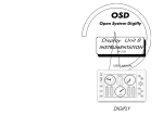
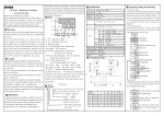
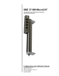
SERIES HB 548 Hardware structure 12 3 45 6 1 0 0 0 0 Installation guide WARNINGS - This manual is a complement ot the Users Manual; it is necessary to get all information here indicated. We recommend then a careful reading and, in case of misunderstandings, please contact QEM for any further information by sending the assistance fax which you shall find enclosed to the manual of installation, maintenance and assistance. - QEM is free from any responsibility for damages to people or things due to unobservance of the instructions and prescriptions contained in this leaflet. We also state that the customer/purchaser must use the instrument according to the instructions supplied by QEM. Any authorization for further use and replacement shall be deemed as valid by QEM, in case of contestation, only if it has been written by QEM - No reprinting or republishing or delivery to third parties of this manual or of its parts is authorized unless a written authorization is provided by QEM. Any infraction shall provoke a request of indemnization for damages on behalf of QEM. - All rights generated by patents or models are reserved. - QEM reserves the right to partially or integrally modify the characteristics of the instrument described and the enclosed documentation - This document is integrally valid except for mistakes or omissions. Manual release 100 Modifications to the manual New manual Modification date 16 / 10 / 01 Issuance and Approval Issued by the Person in Charge for the Documentation: ............................................................................................. Approved by:- Person in Charge of Technical Office: ................................................................................................ - Person in Charge of Commercial Office: .......................................................................................... - Person in Charge for the Product: ............................................................................................. Technical guide SB548100 Page 2 of 16 Available options in HB 548 AVAILABLE OPTION LEGEND Version Description . Basic version. A Output U1 and U2 for stepper motors control. B Bi-directional counter 12V - 100KHz. C Bi-directional counter 5V - 20KHz. D No bi-directional counter and zero pulse. Option Description A Step analog output with +/-15 bits resolution. C CNC analog output with +/- 15 bits resolution. P Epicicloidal CNC analog output with +/- 15 bits resolution L20 20 digital output. U8 8 power digital output. U12 12 power digital output. U16 16 power digital output. U20 20 power digital output. E 5 digital output and 4 digital input. RS RS 232C. DF RS 422. MD RS 485. Technical guide SB548100 Page 3 of 16 Specifications series HB 548 CARATTERISTICHE TECNICHE, ELETTRICHE E MECCANICHE OPERATION ENVIROMENT Temperature: ................................................ 0÷50 °C Humidity: ....................................................... 90% without condensate Max. altitude: ................................................ 2000 m on sea level Atmosphere: ................................................. No corrosive gas Temperature of transport and storage: ..........-25÷70 °C Degree of protection of the container............. IP41 (Conform to EN 60529) Degree of frontal protection: ..........................IP51 (Conform to EN 60529) Resistance to vibrations:...............................Conform to IEC 68-2-6 (Theoretical data) Resistance to shocks: .................................. Conform to IEC 68-2-27 (Theoretical data) Immunity to interferences: ............................. Conform to EN 50082-2 Emission levels: ............................................Conform to EN 50081-2 The technical characteristics specified are valid if you observed all instructions of the Manual of installation, maintenance and assistance. GENERAL ELECTRICAL SPECIFICATIONS Instruments power supply:.................................................................Choice between 24-115-230 Vac ± 15% 50/60 Hz Absorption in maximum hardware configuration:................................... 16 VA Display:............................................................................................6 display h=10 mm + 9 display h=8 mm high luminosity red colour Memory:...........................................................................................Non volatile by semiconductor Microprocessor:................................................................................ H8-520 16 bit - 20 MHz Power supply issued by the instrument:.............................................. 12 Vdc - 150 mA +/- 4% Attention: the dates related to the current supplied by the instrument are to be considered as maximum values. You must perform a careful check of the absorption and forecast if necessary some auxiliary feeders external to the instrument. Technical guide SB548100 Page 4 of 16 Specifications series HB 548 MECHANICAL SPECIFICATIONS 72 66 Front sight Posterior sight 134 66 66 + 0,7 144 119 134 + 1,0 The overall size, the drilling hole and everything described in this paragraph must be deemed as valid for those instruments having hardware configurations being different from those int he figure N.B. All sizes are in millimeters. Type of instrument: ........ In a closed container, size according to DIN 43700 72 x 144 x 119 mm Electric connections: ......Extractable polarized terminalboard with screw fixations. Æ of stiff and flexible wires: 0.2÷2.5 mm serial connection: male 9 PIN Keyboard: ......................In plexiglass covered with antiscratch polyester with 16 mechanical keys and 5 red signalling leds. Weight:.......................... 1050 gr (in the maximum hardware configuration) Technical guide SB548100 Page 5 of 16 HB 548: logical card ELECTRICAL CONNECTIONS LOGIC CARD: TERMINAL DESCRIPTION - ELECTRICAL CONNECTION EXAMPLE Network XXX Power supply voltage XXX Power supply voltage GND Ground wiring Phase Phase (QFRGHU313 IRUDUHDVRQRUSRXUSRVHRIH[DP SOH + Positive transductor power supply - Negative transductor power supply C1 Common terminal for outputs U1÷U5 U1 Output U1 U2 OutputU2 U3 OutputU3 U4 OutputU4 U5 OutputU5 PE Terminal for tranductor polarization PH Input phase 1 transductor PH Input phase 2 transductor Z Zero pulse for transductior P1 Terminal for input I1÷I6 polarization I1 Input I1 I2 InputI2 I3 InputI3 I4 InputI4 I5 InputI5 I6 Ingresso Input Important: read carefully notes at page 13 and 14 Note: terminal 12 must be always connected, otherwise the insturment will not read the encoder pulses. The connection depends on the encoder type: a) Encoder NPN --> terminal 12 must be connected to the positive of the transductor supply (terminal 4) b) Encoder PNP--> terminal 12 must be connected to the positive of the transductor supply (terminal 5) c) Encoder Push-Pull --> terminal 12 must be connected to the positive or to the negative of the transductor supply (morsetto 4 o 5) Technical guide SB548100 Page 6 of 16 HB 548: logical card ELECTRICAL SPECIFICATIONS OF THE LOGICAL CARD Digital inputs Optoisolation .......................................................................................... 2500 V rms Polarization type .................................................................................... NPN - PNP Nominal working voltage .........................................................................12 Vdc Voltage in logical state 0 ........................................................................ 0÷1,5 V Voltage in logical state 1 ........................................................................ 10,5 V÷26,5 V Input resistance .....................................................................................1.5 KW Internal voltage drop ............................................................................... 1.2 V Minimum acquisition time ......................................................................500 ms Minimum acquisition time (interrupt = I1) ................................................ 50 ms Note: minimum acquisition time are a hardware specification.For the functionality of the input please refer to the USER MANUAL of your instrument. Bi-directional counting inputs (version ".") Maximum frequency ...............................................................................20 KHz Optoisolation .......................................................................................... 2500 V rms Polarization type .................................................................................... NPN - PNP Nominal working voltage .........................................................................12 Vdc Voltage in logical state 0 ........................................................................ 0÷1.5 V Voltage in logical state 1 ........................................................................ 10.5÷13 V Input resistance .....................................................................................1,5 kW Internal voltage drop ............................................................................... 1.2 V Bi-directional counting inputs (version B) Like the standard with the following exception: Maximum frequency:...........................................................................100 KHz Bi-directional counting inputs (version C) Like the standard with the following exception: Nomina working voltage .......................................................................... 5 Vdc Voltage in logical state 0 ........................................................................ 0÷1V Voltage in logical state 1 ........................................................................ 3.5÷5.5 V Bi-directional counting inputs (version D) Counting inputs and zero pulse are not installed. Static outputs Optoisolation .......................................................................................... 2500 V rms Commutable load ................................................................................... AC - DC (NPN - PNP) Maximum working voltage ......................................................................24 Vac/dc Internal voltage drop ............................................................................... 2.5 V Maximum current ................................................................................... 70 mA Dispersion current ..................................................................................20 mA ON-OFF commutation time .................................................................... max 120 ms OFF-ON commutation time .................................................................... max 8 ms Note: commutaiton time depends on the load type; data indicated are reffered to resistive loads. Static outputs (version A) Like the standard static outputs with the following exception: Output U1 and U2 are designed to control a stepper motor with maximum frequency of 20 KHz. Note: with version A, outputs in the logical card can be only NPN. Technical guide SB548100 Page 7 of 16 HB 548: expansion card (options E, C, A, P) EXPANSION CARD (OPTIONS E, C, A, P): TERMINAL DESCRIPTION - ELECTRICAL CONNECTION EXAMPLE Motor drive A1 Analog output GA Common for analog output C2 Common terminal for outputs U6÷U10 U6 Output U6 U7 OutputU7 U8 OutputU8 U9 OutputU9 U10 OutputU10 P2 Polarization terminal for inputs I7÷I10. I7 Input I7 I8 Input I8 I9 Input I9 I10 Input I10 Important: read carefully notes at page 13 and 14 ELECTRICAL FEATRES FOR EXPANSION CARD (OPTIONS E, C, A, P) Digital Inputs (option E) Optoisolation ..........................................................................................2500 V rms Polarization type ....................................................................................NPN - PNP Nominal working voltage .........................................................................12 Vdc Voltage in logical state 0 ........................................................................0÷1,5 V Voltage in logical state 1 ........................................................................10,5 V÷26,5 V Input resistance .....................................................................................1.5 KW Internal voltage drop ............................................................................... 1.2 V Minimum acquisition time ......................................................................500 ms Note: minimum acquisition time are a hardware specification.For the functionality of the input please refer to the USER MANUAL of your instrument. Static outputs (option E) Optoisolation ..........................................................................................2500 V rms Commutable load ................................................................................... AC - DC (NPN - PNP) Maximum working voltage ......................................................................24 Vac/dc Internal voltage drop ............................................................................... 2.5 V Maximum current ................................................................................... 70 mA Dispersion current ..................................................................................20 mA ON-OFF commutation time .................................................................... max 120 ms OFF-ON commutation time .................................................................... max 8 ms Note: commutaiton time depends on the load type; data indicated are reffered to resistive loads. Technical guide SB548100 Page 8 of 16 HB 548: expansion card (options E, C, A, P) Analog outputs CNC (option C) Voltage range ......................................................................................... ± 10 V Resolution ..............................................................................................16 bit Isolation .................................................................................................2500 V Maximum current ................................................................................... 1 mA DV f.s. : DI .............................................................................................95 mV/mA Step analog outputs (option A) Analog output with step outline. Specifications like analog outputs CNC (option C). Epicicloidal analog outputs (option P) Analog output with epicicloidal outline to prevent mechanical stress. Specifications like analog outputs CNC (option C). Technical guide SB548100 Page 9 of 16 HB 548: exoansion card (options Lx, Ux) EXPANSION CARD (OPTIONS LX, UX): TERMINAL DESCRIPTION - ELECTRICAL CONNECTION EXAMPLE Electricla connections for cards Ux and Lx are the same; the only dofference is the maximum voltage and current commutable value. The terminal in figure below shows the card U20 (or L20); for the cards U8, outputs are available till terminal number31, for cards U12 till number 36, for cards U16 till number 40, for cards U20 till number 44. C2 Common terminal for outputs U6 ÷ U15 U6 Output U6 U7 Output U7 U8 Output U8 U9 Output U9 U10 Output U10 U11 Output U11 U12 Output U12 U13 Output U13 U14 Output U14 U15 Output U15 C3 Common terminal for outputs U16 ÷ U25 U16 Output U16 U17 Output U17 U18 Output U18 U19 Output U19 U20 Output U20 U21 Output U21 U22 Output U22 U23 Output U23 U24 Output U24 U25 Output U25 Important: read carefully notes at page 13 and 14 Technical guide SB548100 Page 10 of 16 HB 548: expansion card (option Lx, Ux) ELECTRICAL SPECIFICATIONS FOR EXPANSION CARD (OPTIONS LX, UX) Static outputs L20 - L12 and L16 OUT OF PRODUCTION. Optoisolation .......................................................................................... 2500 V rms Commutable load ................................................................................... AC - DC (NPN - PNP) Maximum working voltage ......................................................................24 Vac/dc Internal voltage drop ............................................................................... 2.5 V Maximum current ................................................................................... 70 mA Dispersion current ..................................................................................20 mA ON-OFF commutation time .................................................................... max 120 ms OFF-ON commutation time .................................................................... max 8 ms Note: commutaiton time depends on the load type; data indicated are reffered to resistive loads. Static power outputs (options U8, U12, U16, U20) Cards with 8, 12, 16, or 20 static outputs. Specifications like the standard outputs with the following exceptions: Maximum working voltage ......................................................................110 Vac/dc Maximum current ................................................................................... 200 mA Dispersion current ..................................................................................1 mA Technical guide SB548100 Page 11 of 16 HB 548: serial interface card SERIAL INTERFACE CARD: TERMINAL DESCRIPTION Option RS Pin 2 = RX = Reception Pin 3 = TX = Transmission Pin 5 = GND = Common serial port Option DF Pin 2 = RX = Reception Pin 3 = TX = Transmission Pin 4 = RX = Reception Pin 8 = TX = Transmission Option MD Pin 2 = A Pin 8 = B Serial RS 232C - RS 422 - RS 485 Corresponding to the electrical standards defined by the serial type. Maximum transmission speed is 9600 baud. For the RS 232C, the maximum cable length is 15 m; for RS 422 and RS 485 maximum length is 1200 m Technical guide SB548100 Page 12 of 16 Installation guide DIRECTIONS FOR CABLING This is an extraction from out Installation, mantainance and assistance manual. Please refer to that manual for designing and execution of the cablings. PLACING In cabling, separate the power part from the command part. The structure must allow a correct air flow for cooling. The installation site must be dry and without vibrations; the enviroment temperature must be stable or anyway between the specified limits (see technical specifications). The instrument position inside the board must be separated from the power components and from the cables connected to the power components (relais, drivers, inverters, brakes, ...). CABLES During the cabling separate phisically the power conductors from the command ones. If the cables must cross each others, the angle between them must be closer to 90 degrees. For the command signals, we suggest to use shielded cables with interlaced conductors; it's strongly suggested the use of shielded cables for transductors, analog IN/OUT, serials. The use of shielded cables for digital IN/OUT increase the reliability of the system. We suggest the use of terminal junctions. TERMINAL Do not use the same terminal for power cables (relais, drivers, inverters, brakes, ...) and signal cables (digital and analog signals IN/OUT, transductor signals,...). Technical guide SB548100 Page 13 of 16 Installation guide POWER SUPPLY We prescribe the use of transformers with the CE logo for the supply of the only instrument; the secondary must NOT be connected to ground (thes eare secondary NOT corrected: 55 - 0 - 55, 0 - 24 with 0 to ground ...) Do not use auto-transformers (even if followed by normal transformers) because this solution does not allow a complete galvanic separation from primay to secondary. Separate the supply of the electronic circuits from the power one. Verify that the transformer power is enough to supply the circuits and verify the transformer gives the nominal power without voltage losses. The same indications are valid for the outputs supply (polarization voltage). FILTERS If working in a medium disturber enviroment, the QEM instrumentation does not need filters; the use of theese devices (preferrable of second order), is suggested in presence of power supply with strong noise. All relais, elettrovalve, coils, brakes, ... in the system must be equipped with suppressors. For loads in AC use RC suppressors. For loads in DC use diods in antiparallel. GROUND Use short ground connection. The maximum resistance for the ground connection is 0.2-0.3 Ohm. RELAIS Dispose the connections parallel to the frame plane. For the inputs machanical/elettromechanical, we suggest the use of relais closed in inert atmosphere with contacs designed for 0.1 mA currents. Use, if possible, the N.A. contact. The suggestion gived for the relais must be used for all the ather contacs type. Technical guide SB548100 Page 14 of 16 NOTE Technical guide SB548100 Page 15 of 16 NOTE Il presente prodotto è uno strumento elettronico e quindi non deve essere considerato una macchina. Di conseguenza non deve sottostare ai requisiti fissati dalla Direttiva CEE 89/392 (Direttiva Macchine). Pertanto si afferma che se lo strumento QEM viene utilizzato come parte componente di una macchina, non può essere acceso se la macchina non soddisfa i requisiti della Direttiva Macchine. La marcatura dello strumento non solleva il Cliente dall'adempimento degli obblighi di legge relativi al proprio prodotto finito. Technical guide SB548100 Page 16 of 16