1
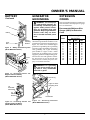
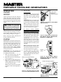
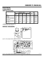
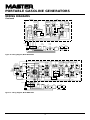
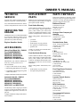
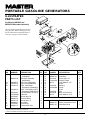
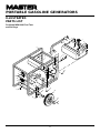
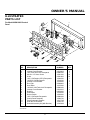
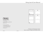
R
PORTABLE GASOLINE
GENERATORS
F
F
U
E
L
OWNER’S OPERATION AND INSTALLATION MANUAL
120
VOL
TS
RES
ET
TES
T
FUL
120
ON
LY
L
SEL POW
ECT ER
OR
120
240
V
120
/240
VO
LTS
EN
000 M
000
HOU
RS
05
1/10
RES
ET
F
F
U
E
L
RES
ET
120
VO
LTS
RES
ET
TES
T
Aut
o-Id
le
ON
OFF
EN
000 M
000
05
HOU
RS
RES
ET
1/10
240
VO
LTS
RES
ET
Generator Models: HWI3000, MGH3000, MGH4000C, MGH4000CI, MGH5000C, MGH5000CI,
MGH5000CIE, MGH6000C, MGH6000CI, MGH7000C, MGH7000CI, and MGH10000
IMPORTANT: Read and understand this manual before operating or servicing
generator. Improper use of generator can cause serious injury. Keep this
manual for future reference.
R
PORTABLE GASOLINE GENERATORS
SAFETY
INFORMATION
1.
WARNINGS
IMPORTANT: Read this owner’s
manual and the engine owner’s
manual carefully. Become familiar with this generator before trying to operate or service it. Know
its uses, limitations, and any hazards involved. Improper use of
generator can cause severe injury or death from explosion, fire,
burns, electrical shock, or carbon monoxide poisoning.
DANGER: Carbon monoxide
poisoning may lead to death!
Engine exhaust contains poisonous carbon
monoxide gas. Overexposure will cause loss
of consciousness and will lead to death. Use
only in well-vented areas. Make sure area
has plenty of free-moving, fresh, outside
air. Never run generator in an enclosed or
confined area. Never run generator inside
occupied building.
Carbon Monoxide Poisoning: Early
signs of carbon monoxide poisoning resemble the flu, with headaches, dizziness,
and nausea. If you have these signs, get
fresh air at once! Some people are more
affected by carbon monoxide than others.
These include pregnant women, persons
with heart or lung disease or anemia, those
under the influence of alcohol, and those at
high altitudes. Make certain you read and
understand all warnings. Keep this manual
for reference. It is your guide to safe and
proper operation of this generator.
Safety information appears throughout these
instructions. Pay close attention to them.
Below are definitions for the safety information listed throughout this manual.
DANGER: indicates a hazard which will
cause severe personal injury, death, or substantial property damage if you ignore warning.
WARNING: indicates a hazard which can
cause severe personal injury, death, or substantial property damage if you ignore warning.
CAUTION: indicates a hazard which will
or can cause minor personal injury or property damage if you ignore warning.
2.
3.
Gasoline presents a hazard of fire or explosion. Gasoline is flammable. Its vapor is explosive.
• Keep fuel out of children’s reach.
• Refuel generator in a well-vented
area. Do not fill fuel tank in the dark.
Do not refuel while engine is running. Unhook all electrical loads and
shut off engine before refueling.
• Do not overfill fuel tank. Always allow room for fuel to expand. If you
overfill tank, fuel can overflow onto
hot generator. This can cause fire or
explosion. After refueling, tightly
close fuel tank cap.
• Do not spill fuel. Fuel or fuel vapor
may ignite. If fuel spills, make sure
area is dry before starting engine.
• Never smoke in refueling area. Never
allow open flames or sparks in area.
• Store fuel in approved container.
Store fuel in a well-vented area free
of open flames or sparks.
Guard against fire hazard. Keep operation area well-vented. Keep generator
at least three feet away from any object. Do not place flammable objects
near generator.
• Do not use generator where flammable vapors are present. Some vapors are heavier than air. These vapors settle in low-lying places.
• Do not use generator in enclosed
spaces. This includes motor home or
RV generator compartments.
Guard against electric shock. Generator
produces high voltage. This high voltage
can cause severe electric shock. Only responsible adults should use generator.
• Properly ground generator before
starting.
• Never let anyone operate or service
generator without proper instructions.
• Avoid contact with live terminals or
bare wires.
• Do not use generator outdoors in rain
or snow.
• Do not use generator near standing
water or snow.
• Do not use if generator is wet or
damp.
• Do not use generator in highly conductive areas. These areas include
metal decking and steelwork.
• Only use grounded extension cords.
2
4.
5.
6.
7.
8.
• Do not use any worn or damaged
electric cords. Electric shock or damage to generator may result.
• Do not wear damp clothing or wet
shoes when using generator.
Guard against burns. Hot engine parts
can cause severe injury. Use caution
and remain alert when using generator.
• Keep children and animals away
from generator while it is running or
hot.
• Keep all covers and shields in place.
Keep them tightly secured.
• The muffler becomes very hot during operation. The muffler remains
hot for a while after shutdown. Do
not touch muffler while it is hot. Do
not let muffler touch anything flammable. Let engine cool before transporting or storing.
Have standby installation to home or
building performed by a licensed electrician. Do not let anyone else wire into
a utility circuit. Personal injury, equipment damage, or damage to home could
occur.
Never connect generator to any existing electrical circuits. The generator
output will back-feed into the utility
power line. This may electrocute a
power company line repair person.
Also, if generator is powering electrical circuits, the chance of an electrical
fire exists.
Battery gives off explosive gases. Keep
sparks, flames, and cigarettes away. Do
not remove or install battery cables
when engine is cranking or running.
Only service or use battery in a wellvented area.
Battery contains sulfuric acid. Battery
acid is poisonous if swallowed. Contact with skin or eyes may cause severe
burns. Do not tilt generator with battery installed. Tilting could cause battery acid to spill. Wear protective clothing and face shield when servicing.
Keep out of children’s reach.
103988
OWNER’S MANUAL
SAFETY
INFORMATION
PRODUCT
IDENTIFICATION
Continued
13.
14.
E
L
U
F
120 Volt
Receptacle
Full Power
Selector Switch
120 Volt
Receptacle
(GFCI)
12
0 VO
LT
S
RE
SE
TE T
ST
FU
LL
PO
WE
R
12
ON 0
LY
12
0
24
0V
120 Volt
Receptacle
(Duplex)
12
0/2
40
UR
S
VO
LT
S
EN
00 M
00
00
HO
05
RE
SE
T
1/1
0
RE
SE
T
Provision for
Auto-Idle Switch
Run Lamp
Hour Meter
Roll Cage
120/240 Volt
Receptacle
Circuit
Breaker
Gas Tank
E
L
Choke
Lever
U
12.
Control
Panel
F
11.
Gas Cap/Fuel Gauge
Fuel
Valve
Lever
Ground
Lug
Starter Grip
Alternator
Engine
Engine ON/
OFF Switch
Oil Dipstick
Figure 1 - Portable Generator (Model MGH4000C Shown)
103988
F
10.
Only a qualified electrical service person should service and repair generator.
• Generator produces high voltage.
Use extreme caution when working
on electrical parts.
• Always remove spark plug wire from
spark plug before servicing. This will
prevent accidental starting.
• When working on generator, avoid hot
muffler, exhaust manifold, and engine
parts. Severe burns may occur.
• Do not work on generator when tired.
• Use only factory approved replacement parts.
Store generator in a well-vented area.
Make sure fuel tank is empty. Never
store with fuel in tank. Vapors may
reach an open flame or spark. Fire or
explosion may result.
Never operate generator
• if engine speed changes greatly
• if engine misfires often
• if powered items overheat
• if electrical output drops
• if it is sparking
• if it produces smoke or flames
• if it vibrates at high levels
• if it has a damaged receptacle
Keep generator and nearby areas clean.
• Keep generator free of oil, mud, and
other foreign matter.
• Remove anything that creates slippery areas around generator.
• Remove oily rags and other items
that create fire hazards.
• Keep a fire extinguisher nearby.
Make sure it is rated ABC by the
NFPA. They are good for all uses.
Consult your local fire department.
• Keep fire extinguisher well maintained. Be familiar with its use.
Know how to stop engine quickly.
Know how to use all controls.
Prolonged exposure to loud noise can
cause hearing loss.
• When working around generator,
wear approved hearing protection.
• Remember neighbors when using
generator.
F
9.
3
R
PORTABLE GASOLINE GENERATORS
GENERAL
INFORMATION
Master portable generators are rugged and
compact. These models provide dependable, trouble-free service. The alternators
are brushless with revolving fields. Honda
gasoline engines provide long life under
heavy use. Honda engines have overhead
valves (OHV). This provides high performance with lower fuel consumption. These
engines are governed to maintain engine
speed of 3600 RPM under load. 3600 RPM
engine speed provides 120/240V, 60 Hz
power.
Additional Features
• Circuit breaker protection
• Spark-arresting muffler (except model
MGH10000)
• Large fuel tank
• Oil alert system
• Electric starter (models MGH5000CIE,
MGH7000C, MGH7000CI, and
MGH10000 only)
• 15-Amp ground fault circuit interrupter
(GFCI) receptacle (Except HWI3000
Model)
UNPACKING
1.
2.
3.
4.
Remove generator from carton.
Remove any protective packaging applied to generator for shipment.
Check for loose or missing parts. Check
for shipping damage. If any parts are
missing or damaged, promptly inform
dealer where you bought generator.
Battery cables are supplied for model
MGH5000CIE,
MGH7000C,
MGH7000CI, and MGH10000 only.
These cables are in a separate bag inside generator carton. You must install
these cables to engine. See Battery,
page 8 for installation instructions.
VENTILATION
DANGER: Use only in wellvented areas. Make sure area has
plenty of free-moving, fresh, outside air. Never run generator in
an enclosed or confined area.
Never run generator inside occupied building. Engine exhaust
contains poisonous carbon monoxide gas. Overexposure will
cause loss of consciousness and
will lead to death.
HIGH AND LOW
TEMPERATURE
OPERATION
Air temperature affects generator output.
Output drops 1% for each 10° temperature
rise above 60° F. Very low temperatures may
make the engine hard to start. See engine
owner’s manual for more information.
This generator needs cooling air to run properly. Never block free-flowing, cooling air
to generator. Overheating will occur without cooling air. This will damage the generator. Keep generator at least three feet
away from any object.
DUST, DIRT, RAIN,
AND SNOW
WARNING: Do not use generator outdoors in rain or snow.
Do not use generator near standing water or snow. Do not use if
generator is wet or damp. Operating generator in these conditions increases the risk of electrocution. Severe injury or death
can occur.
Do not use generator in extremely dusty or
dirty conditions. This will severely affect its
life. Keep generator clean. Do not allow
dust, dirt, rain, or snow to collect on it.
Protect generator from outdoor elements.
4
103988
OWNER’S MANUAL
SPECIFICATIONS
MGH5000C
MGH4000C MGH5000CI MGH6000C
MGH4000CI MGH5000CIE MGH6000CI
MGH7000C
MGH7000CI MGH10000
HWI3000
MGH3000
Rated Wattage
2500
2500
4000
5000
6000
7000
10,000
Rated Amperage
120 V
240 V
20.8
––
20.8
––
33.3
16.7
41.7
20.8
50
25
57
28.3
83.3
41.7
MODEL
Electrical
Receptacle
120-V Duplex
––
––
Yes
Yes
Yes
Yes
Yes
120-V, 20-A Duplex
Yes
––
––
––
––
––
––
120-V, 15-A GFCI
No
Yes
Yes
Yes
Yes
Yes
Yes
120-V Twist-Lock
No
No
30 Amp
30 Amp
30 Amp
30 Amp
30 Amp
120/240-V Twist-Lock
No
No
20 Amp
20 Amp
20 Amp
30 Amp
30 Amp
120-V Full-Power Switch No
No
Yes
Yes
Yes
No
No
120/240-V, 5.0-A
No
No
No
No
No
No
Yes
5.5
5.5
8
9
11
13
20
General
Honda Engine H.P.
Honda Model
Fuel Type
Fuel Tank Capacity
Oil Alert System
Start Method
Weight (pounds)
GX160K1VX GX160K1VX
GX240K1VA
GX270VA
GX340K1VA
Gasoline
Gasoline
Gasoline
Gasoline
Gasoline
GX390K1VXE GX620VXA3
Gasoline
Gasoline
3.9 qt.
3.9 qt.
5 gal.
5 gal.
5 gal.
5 gal.
5 gal.
Yes
Yes
Yes
Yes
Yes
Yes
Yes
Recoil
Recoil
Recoil
Recoil/Elec.
Recoil
Electric
Electric
85.5
85.5
139
173
191
247
325
* Single-phase, 1.0 power factor
Note: Ratings apply to SAE standard conditions. Reduce ratings 3 1/2% for each 1000 feet above sea level and 1% for each 10° Fahrenheit
rise above 60°F.
103988
5
R
PORTABLE GASOLINE GENERATORS
120 VOLT ONLY: This position sends full
power to the 120V receptacles only. 240V
power is not available. Use this position
when powering 120V items only.
GENERATOR
FEATURES
OIL ALERT SYSTEM
The oil alert system protects the engine from
low oil damage. This system automatically
shuts down the engine and prevents engine
restarting if the oil level falls too low.
Note: When this happens, the engine switch
remains in the ON position. The oil alert
system is wired into the ON/OFF Switch.
120/240 VOLT: This position sends full
power to the 120/240V receptacle. It also
powers the 120V receptacles at reduced
wattage capacity.
Full Power
120 V
ONLY
120/
240V
Selector
If this system shuts down the engine, the
engine will not start until you add oil. Add
oil to engine (see Engine Oil, page 7).
Note: Operate generator on a level surface.
If not level, the oil may flow away from the
oil level sensing device. This will cause the
oil alert system to shut down engine.
120 VOLT ONLY Position
120/
240V
Selector
OFF
HONDA
Models
MGH5000CIE,
MGH7000C,
MGH7000CI, and
MGH10000
ON
OFF
START
ENGINE SW
CIRCUIT
BREAKER
Figure 2 - Engine Switch Location
FULL POWER SELECTOR
SWITCH
All models except HWI3000, MGH3000,
MGH7000C, MGH7000CI, and MGH10000
have a full power selector switch on the
control panel. The switch has two positions:
120 VOLT ONLY, and 120/240 VOLT.
When protected by the GFCI, you may still
feel a shock, but the GFCI should cut it off
quickly. A person in normal health should
not receive serious injury. Note: Infants and
very small children may still be affected.
Full Power
120 V
ONLY
Models HWI3000, MGH3000, MGH4000C,
MGH4000CI, MGH5000C, MGH5000CI,
MGH6000C, and MGH6000CI
All models (Except HWI3000) have a 120volt ground fault circuit interrupter (GFCI)
receptacle. The GFCI receptacle is on the
control panel or top cover of alternator
(model MGH3000 only). The GFCI protects you against hazardous electrical shock
caused when your body becomes a path
through which electricity travels to reach
ground. This could happen when you touch
an appliance or cord that is ‘live’ through
faulty mechanism, damp or worn insulation, etc.
Test Procedure
See engine owner’s manual for more
information.
ENGINE SW
ON
GROUND FAULT CIRCUIT
INTERRUPTER RECEPTACLE
120/240 VOLT Position
Check the GFCI receptacle every month.
This insures it is working right.
1. Push black TEST button. Red RESET
button should pop out. This should trip
GFCI, resulting in no electrical power
at receptacle. Verify this by plugging
test lamp with good bulb into receptacle. If lamp does not work, GFCI receptacle is good.
Figure 3 - Full Power Selector Switch
IMPORTANT: Do not move the full power
selector switch while powering electrical
items. Unplug all items before moving
switch. Failure to do so can damage switch.
Models HWI3000, MGH3000, MGH7000C,
MGH7000CI, and MGH10000 do not have
this switch. These models provide full power
to all receptacles.
ELECTRIC START
(Models MGH5000CIE,
MGH7000C, MGH7000CI, and
MGH10000)
Models MGH5000CIE, MGH7000C,
MGH7000CI, and MGH10000 have electric starters. A battery is not supplied with
generator. You must provide a 12-volt, 32amp-hour battery. For more battery information, see Battery, page 8.
WARNING: If RESET button
does not pop out, do not use the
GFCI receptacle. Contact a qualified electrician for repairs.
2.
If the GFCI receptacle tests okay, restore power by pushing the RESET
button back in. The test lamp should
work at this time. IMPORTANT: You
must press the RESET button firmly
and fully. It should lock into place. If
the GFCI does not lock into place, do
not use receptacle. Contact a qualified
electrician for repairs.
RE
SE
TE T
ST
Figure 4 - GFCI Receptacle
6
103988
OWNER’S MANUAL
GENERATOR
FEATURES
Continued
ENGINE CIRCUIT BREAKER
(Models MGH5000CIE,
MGH7000C, MGH7000CI, and
MGH10000)
This circuit breaker, or fuse, protects the
battery charging circuit. A short circuit will
trip the circuit breaker. The circuit breaker
will also trip if you install battery wrong.
Push circuit breaker button to reset. On
Model MGH10000, the fuse is located inside of the Keyswitch box.
ON
OFF
Engine Circuit
Breaker Button
START
ENGINE SW
CIRCUIT
BREAKER
ON/push OFF
Figure 5 - Engine Circuit Breaker
RECEPTACLE CIRCUIT
BREAKER
ENGINE OIL
We ship the generator without oil in the
engine crankcase. You must add oil before
starting engine. See engine owner’s manual
for specific oil type.
CHECKING OIL LEVEL AND
ADDING OIL
Follow steps below to check oil level. Make
sure engine is level and stopped.
1. Remove dipstick (see Figure 7). Wipe
dipstick clean.
2. Insert dipstick into oil filler neck. Do
not screw it in. Oil level should be at
top of filler neck. Oil should cover most
of dipstick. For Model MGH10000
only, the oil should be between the two
dots on dipstick.
3. If level is low, fill to top of oil filler
neck (see Figure 7). For Model
MGH10000 only, fill to top dot on dipstick. Only use oil recommended in
engine owner’s manual.
Note: If oil level is too low, oil alert system
will shutdown engine and prevent engine
from restarting.
The circuit breakers protect the receptacles
and alternator. Overloading generator will
trip circuit breaker. A short circuit in item
being powered will also trip breaker. If this
occurs, unplug electrical load from receptacle. Let circuit breaker cool down. Push
circuit breaker button to reset.
Electric motors need higher starting current.
They require up to three-times their rated
wattage to start. The starting current needed
may be too high. This can cause nuisance
circuit breaker tripping. To help prevent
this, start electric motors first. Connect additional items to generator after starting
motors. If this continues to happen, reduce
the total generator load.
20
Normal
Oil Level
At Top Of
Filler Neck
Dipstick
Oil
Figure 7 - Checking Oil Level (Model
MGH4000C Shown)
20
Tripped
Figure 6 - Receptacle Circuit Breaker
Button
Note: High ambient temperature will cause
nuisance tripping.
103988
FUEL
7
WARNING: Gasoline presents
a hazard of fire or explosion.
Gasoline is flammable. Its vapor
is explosive.
• Keep fuel out of children’s
reach.
• Refuel generator in a wellvented area. Do not fill fuel tank
in the dark. Do not refuel while
engine is running. Unhook all
electrical loads and shut off
engine before refueling.
• Do not overfill fuel tank. Always allow room for fuel to
expand. If you overfill tank, fuel
can overflow onto hot engine.
This can cause fire or explosion. After refueling, tightly
close fuel tank cap.
• Do not spill fuel. Fuel or fuel
vapor may ignite. If fuel spills,
make sure area is dry before
starting engine.
• Never smoke in refueling area.
Never allow open flames or
sparks in area.
• Store fuel in approved container. Store fuel in a wellvented area free of open flames
or sparks.
Use clean, fresh, unleaded gasoline. Use
gasoline with octane rating of 86 or higher.
Service station gasoline pumps should display the octane rating. Using gasoline with
lower octane level could damage engine.
Avoid getting dirt, dust, or water in fuel
tank. Do not mix oil with gasoline.
See engine owner’s manual for more
information.
R
PORTABLE GASOLINE GENERATORS
BATTERY
(Models MGH5000CIE,
MGH7000C, MGH7000CI, and
MGH10000)
WARNING: Battery gives off
explosive gases. Keep sparks,
flames, and cigarettes away. Do
not remove or install battery
cables when engine is cranking
or running. Only service or use
battery in a well-vented area.
WARNING: Battery contains
sulfuric acid. Contact with skin
or eyes may cause severe burns.
Do not tilt generator with battery
installed. Tilting could cause battery acid to spill. Wear protective
clothing and face shield when
servicing. Keep out of children’s
reach.
• If battery acid gets on your
skin, wash with water.
• If battery acid gets in your eyes,
flush with water at least 15
minutes. Call a doctor at once.
Battery acid is poisonous.
• If swallowed, drink large
amounts of water or milk. Follow with milk of magnesia or
vegetable oil. Call a doctor at
once.
Always wear safety glasses when working
with battery. Make sure battery terminals
are clean. Make sure cable connections are
tight.
Always shut down engine before removing
or attaching battery cables. Always remove
the negative (–) cable first. Always attach
negative (–) cable last.
INSTALLING BATTERY
CABLES TO ENGINE
1.
Attach the red, positive (+) battery
cable to the starter solenoid on engine
(see Figure 8). The starter solenoid is
located directly above the starter on
Model MGH10000. This cable is factory installed.
CAUTION: Do not over tighten
positive terminal on starter solenoid. Positive terminal could rotate and cut into negative terminal, causing a short.
2.
Attach the black, negative (–) battery
cable to the engine block. Use the bolt,
nut, and two washers provided with the
battery cables. Use long mounting hole
on opposite side of engine from starter
solenoid. Attach cable as shown in Figure 9.
Black,
Negative (–)
Battery Cable
Figure 9 - Connecting Black, Negative (-)
Battery Cable to Engine Block (Model
MGH7000C Shown)
MOUNTING BATTERY TO
GENERATOR
1.
2.
3.
4.
CAUTION: If you remove battery, insulate the red, positive (+)
battery cable terminal. Insulate
with electrical tape. Exposed terminal may spark when generator
runs.
IMPORTANT: Make sure battery connections are the correct polarity. Electric start
generators use negative ground, 12-volt DC
starting system.
Models MGH5000CIE, MGH7000C,
MGH7000CI, and MGH10000 have an electric starter. A battery is not supplied with
generator. You must provide a 12-volt, 32amp-hour battery. The positive and negative battery cables are supplied with generator. You must install these cables before
mounting battery.
Secure battery to generator by battery
hold-down system. This system consists
of the battery mounting bracket, hook
bolts, and nut (see Figure 10).
Note: Model MGH10000 battery is located on opposite side as shown (see
Figure 11, page 9).
Locate the red, positive (+) battery
cable from starter solenoid. Connect it
to the positive (+) battery terminal (see
Figures 12 and 13, page 9).
Locate the black, negative (–) battery
cable attached to engine block. Connect
it to the negative (–) battery terminal
(see Figures 12 and 13, page 9).
Check battery before starting engine.
Make sure fluid levels are full. Make
sure battery is charged.
See engine owner’s manual for more
information.
Starter
Solenoid
Battery
Mounting
Bracket
Red, Positive (+)
Battery Cable
Nut
Figure 8 - Connecting Red, Positive (+)
Battery Cable to Engine Starter Solenoid
(Model MGH7000C Shown)
FUL
L POW
ER
120
ON
LY
120
240
V
EN
000 M
000
HOU
RS
05
1/10
Battery
Hook
Bolt
Figure 10 - Battery Hold-Down System
(Model MGH7000C Shown)
8
103988
OWNER’S MANUAL
BATTERY
GENERATOR
GROUNDING
Continued
E
F
FU
L
Nut
WARNING: You must properly earth-ground generator before starting. This will help guard
against deadly electric shock.
Only use grounded plugs with
generator. Only use grounded extension cords. Only use threewire or double-insulated power
tools.
Battery
Battery
Mounting
Bracket
Hook
Bolt
Figure 11 - Battery Hold-Down System
(Model MGH10000 Shown)
TO ENGINE
BLOCK
FUL
L PO
WE
R
120
ON
LY
120
240
V
EN
000 M
000
HO
UR
05
S
1/10
Grounding generator helps prevent electric
shock from a ground fault condition. Locate
ground lug on end of generator housing (see
Figure 12). Attach a #10 stranded-copper
ground wire to ground lug. Drive grounding
point into ground. Grounding point can be a
stake, grounding rod, or pipe. Grounding
point should be copper or brass. Attach
ground wire to grounding point. You must
supply the ground wire and grounding point.
These do not come with generator. Follow
the National Electrical Code and all state
and local codes. Consult your power company or a licensed electrician.
TO STARTER
SOLENOID
WARNING: For a grounding
point, do not use metal pipe being used to carry combustible
materials or gases.
Figure 12 - Connecting Positive and
Negative Cables to Battery
(Model MGH7000C Shown)
F
FU
E
L
Copper or Brass
Grounding Point
F
TO
STARTER
SOLENOID
F
U
E
L
Ground Lug
TO
ENGINE
BLOCK
Ground Wire
Alternator
Figure 13 - Connecting Positive and
Negative Cables to Battery
(Model MGH10000 Shown)
103988
Figure 14 - Grounding Generator
(Model MGH4000C Shown)
9
EXTENSION
CORDS
Only use grounded extension cords. Be sure
to use extension cord with proper wire gauge
size. See chart below.
Recommended Minimum Wire
Gauges (AWG) for Extension
Cords
Ampere
Load
2
3
4
5
6
8
10
12
14
16
20
AWG for Length of
Cord in Feet
50'
100'
150'
18
18
16
16
16
16
16
14
14
12
10
18
18
16
16
16
14
14
14
12
12
10
18
18
16
16
14
12
12
12
10
10
8
R
PORTABLE GASOLINE GENERATORS
STANDBY
INSTALLATION TO
HOME OR
BUILDING
1.
WARNING: Have standby installation performed by a skilled,
licensed electrician. Do not let
anyone else wire into a utility
circuit. Personal injury, equipment damage, or damage to home
could occur.
2.
IMPORTANT: This generator will not
power your entire home. Most home utility
electric service is more than 60 amps. This
will exceed generator output. Only power
needed items during a power outage. Make
sure total wattage of electrical load does not
exceed rated wattage of generator.
You may need to use this generator as a
standby power source. During a power outage, the generator will power selected items
in a building. Have generator and additional
wiring installed by a skilled, licensed electrician. This is not a do-it-yourself job. Follow all local codes.
WARNING: The electrician
must install a double-throw transfer switch. This isolates existing
electrical circuits from the utility
power line. If not isolated, generator output will back-feed into
utility power line. This may electrocute a power company line
repair person.
DETERMINING
ELECTRICAL LOAD
FOR GENERATOR
You must decide what electrical load your
generator can power. Do this before using
generator. Use the following four-step
method. It will help you select a load that is
not too large. Make sure total wattage of all
electrical loads does not exceed rated wattage of generator. For rated wattage of your
generator, see Specifications, page 5. Electric motors present a special problem when
figuring load. Read Step 3 carefully.
3.
Make two lists of items you want powered by generator. List all motors and
motor powered appliances in one. List
all lights, small appliances, etc. in the
other. For standby service to home or
building, only include items you must
power.
Enter running watts of each item except motors. The light bulb or appliance nameplate lists its wattage. Remember, 1KW = 1000 watts. Note: The
nameplate may not list wattage. It may
only list volts and amps. The formula
for finding wattage is: Volts x Amps =
Watts. For example: An appliance
nameplate states 3 amps at 120 volts. 3
amps x 120 volts = 360 watts.
Electric motors present a special problem. They require up to three-times
their rated wattage to start. Chart 2,
below, shows starting watts for differ-
4.
ent size motors. For example: an electric motor nameplate states 5 amps at
120 volts. 5 amps x 120 volts = 600
watts running. Multiply this figure by
3. This will show the starting watts
needed. 600 watts x 3 = 1800 watts to
start. When figuring the generator load
for motors, you must use the starting
watts figure. Do not use the running
watts figure. Note: Some motors require nearly the same wattage to run as
to start. These items include saws,
drills, hair dryers, and food mixers. See
Chart 1 for typical appliance wattage
examples.
Add watts and starting watts of all
items. This total must not be larger than
the rated wattage of your generator. It
is a good idea to have up to 25% extra
capacity for future needs or extra
equipment.
Chart 1 - Typical Electric Appliance Wattages
Running Starting
Watts
Watts
Equipment
Light bulb (100W)
Radio
Fan
Television
Furnace fan (1/3 hp)
with blower
Vacuum cleaner
Sump pump (1/3 hp)
Refrigerator/freezer
6" Circular saw
Floodlight
100
150
200
400
100
150
600
400
600
600
700
800
800
1000
1800
750
2100
2400
1000
1000
Equipment
1/2" Drill
Toaster
Coffee maker
Skillet
14" Chain saw
Water well pump
(1/2 hp)
Hot plate/range
(per burner)
10" Table saw
Water heater
(storage-type)
Running
Watts
Starting
Watts
1000
1200
1200
1200
1200
1250
1200
1200
1200
1500
1000
3000
1500
2000
1500
6000
5000
5000
Chart 2
Approximate Starting Watts*
Motor
HP
Rating
Approximate
Running
Watts
Universal
Motors
(small appliance)
Repulsion
Induction
Motors
Capacitor
Motors
Split
Phase
Motors
1/8
1/4
1/3
1/2
3/4
1
1 1/2
2
3
275
400
450
600
850
1000
1600
2000
3000
400
500
600
750
1000
1250
1750
2350
x
600
850
975
1300
1900
2300
3200
3900
5200
850
1050
1350
1800
2600
3000
4200
5100
6800
1200
1700
1950
2600
x
x
x
x
x
* – Always use starting watts, not running watts, when figuring correct electrical load.
x – Motors of higher horsepower are not generally used.
10
103988
OWNER’S MANUAL
OPERATION
Model MGH10000 also has a 120/240V,
50-amp receptacle (see Figure 15).
POWER CORD AND PLUG
REQUIREMENTS
GENERAL INFORMATION
Model HWI3000 has only the 120V, 20amp duplex receptacle.
120V, 30-amp twist-lock receptacle
• NEMA L5-30P plug
• Three-wire, 30-amp cord
This generator is not large enough to power
your entire home. Do not connect generator
to any existing electrical circuits. Plug items
directly into generator receptacles. Do not
exceed amperage rating of receptacles. Only
use grounded cords.
DANGER: Use only in wellvented areas. Make sure area has
plenty of free-moving, fresh, outside air. Never run generator in
an enclosed or confined area.
Never run generator inside occupied building. Engine exhaust
contains poisonous carbon monoxide gas. Overexposure will
cause loss of consciousness and
will lead to death.
DANGER: Never connect generator to any existing electrical
circuits. The generator output will
back-feed into the utility power
line. This may electrocute a power
company line repair person. Also,
if generator is powering electrical circuits, the chance of an electrical fire exists.
Model MGH3000 has only the 120V, 15amp GFCI duplex receptacle.
120V, 15-Amp GFCI Duplex
120V, 15-Amp Duplex
120/240V, 20 or 30Amp Twist-Lock
12
0V
OL
TS
120/240V, 20 or 30-amp twist-lock
receptacle
• NEMA L14-20P (20-amp) or L14-30P
(30-amp) plug
• Four-wire, 20-amp or 30-amp cord
120/240V, 50-amp receptacle
• NEMA L14-50P
• Four-wire, 50-amp cord
RE
SE
TE T
ST
120/240 Volt
20 Amp
12
ON 0
LY
Neutral
120V
120V
12
24 0
0V
EN
M
00
00
0
00
HO
UR
S
5
1/10
120V, 30-Amp
Twist-Lock
RE
w
SE
T
RE
SE
T
X
(Hot)
Ground
(Green)
Y
L14-20P
Plug
X
G
Ground
W
(Neutral)
Y
(Hot)
RE
SE
T
Neutral
120V
120V
24
0V
OL
TS
RE
SE
T
RE
SE
T
120/240 Volt
20 and 30
Amp
L14-20P
Plug
w
Y
X
Ground L14-50P
Plug
G
RE
SE
T
Note: We supply the engine owner’s manual
with generator. Refer to that manual for
questions concerning engine operation.
Ground
Ground
(Green)
X
(Hot)
Y
Neutral
120V
120V
120V
USING RECEPTACLE
G
X
w
w
Y
120V
Neutral
X
G
Note: Do not exceed amperage rating of
receptacles. Exceeding rating will trip receptacle circuit breaker.
Use receptacles properly. Improper use could
damage generator. Use only grounded extension cords. Power only grounded or
double-insulated items. Do not overload
receptacles. All generators (except models
HWI3000 and MGH3000) have the following receptacles (see Figure 15):
• 120V, 15-amp GFCI duplex receptacle
• 120V, 30-amp twist-lock receptacle
• 120/240V, 20 or 30-amp twist-lock
receptacle
• 120V, 15-amp duplex receptacle
120/240V, 50-Amp
(Model MGH10000 only)
Figure 15 - Receptacle Locations
Y
(Hot)
W
(Neutral)
Ground
L14-30P
Plug
Figure 16 - Cord and Plug Configurations
Continued
103988
11
R
PORTABLE GASOLINE GENERATORS
OPERATION
4.
Continued
PRESTART
Operate generator on a firm, dry, and clean
surface. The surface must be level. Protect
generator from heavy dust, sand, dirt, rain,
or snow. Do not locate generator near standing water and snow. Make sure area is wellvented.
WARNING: Only responsible
adults should use generator.
Never let anyone operate generator without proper instructions.
Note: If oil level is too low, oil alert system
will keep engine from starting (see Oil Alert
System, page 6). Make sure oil level is full
before starting. See Engine Oil, page 7.
Before starting the engine, disconnect all
electric loads from generator.
STARTING
IMPORTANT: The engine speed is preset.
The throttle is locked in preset position. Do
not adjust throttle. Preset position lets engine run at 3600 RPM under load. The
engine must maintain 3600 RPM for generator to create correct voltage. Running
engine at lower speeds will damage generator and powered items.
IMPORTANT: Never start generator with
electrical loads connected. Start engine before adding electrical loads.
1. Make sure gasoline tank is full. See
Fuel, page 7 for fuel information.
2. Move fuel valve lever to the ON position (see Figure 17).
3. Move choke lever fully to the left (see
Figure 17) or pull choke button out
(Model MGH10000 only, see Figure
18). This closes the choke.
Note: You may not need to close choke
if engine is warm or air temperature is
high.
5.
Start the engine.
A. Recoil Starter
Turn engine switch to the ON position
(see Figures 19 and 20). Remove slack
from starter rope by lightly pulling
starter grip. Next, pull starter rope
briskly.
IMPORTANT: Do not let starter grip
snap back against engine. Return it gently. This will prevent damage to starter.
Note: If engine does not start, check
the oil in the crankcase. Add oil as necessary. Be sure engine is on a level surface. See Oil Alert System, page 6.
B. Electric Starter (Models
MGH5000CIE,
MGH7000C,
MGH7000CI, and MGH10000 Only)
Turn the engine switch to the START
position (see Figure 20). Hold it there
until engine starts. When engine starts,
let switch return to the ON position.
IMPORTANT: Do not use electric
starter more than five seconds. Starter
motor damage may occur. If engine
fails to start, release the switch and wait
ten seconds. After ten seconds, try starting again.
Note: If engine does not start, check
the oil in the crankcase. Add oil as necessary. Be sure engine is on a level surface. See Oil Alert System, page 6.
As engine warms up, slowly move
choke lever fully to the right (see Figure 21). This opens the choke. On
Model MGH10000, the choke will automatically open.
Choke Lever (Closed Position)
Choke Button
Pulled Out
(Closed Position)
Figure 18 - Choke Button Closed (Model
MGH10000 Only)
ENGINE SW
ON
OFF
Figure 19 - Engine Switch In ON Position
(All Models Except MGH5000CIE,
MGH7000C, and MGH10000)
HONDA
ON
OFF
Engine
Switch
START
ENGINE SW
CIRCUIT
BREAKER
ON/push OFF
Figure 20 - Engine Switch (Models
MGH5000CIE, MGH7000C, MGH7000CI,
and MGH10000 Only)
Choke Lever (Open Position)
Fuel Valve Lever (ON Position)
Figure 17 - Fuel Valve Lever On, Choke
Lever Closed (Model MGH4000C Shown)
Figure 21 - Choke Lever Opened (Model
MGH7000C Shown)
12
103988
OWNER’S MANUAL
OPERATION
STOPPING ENGINE
Continued
IMPORTANT: The engine speed is preset.
The throttle is locked in preset position. Do
not adjust throttle.
HIGH ALTITUDE OPERATION
This generator will not perform well at high
altitudes without proper adjustment. See
engine owner’s manual for details.
ADDING ELECTRICAL
LOADS
IMPORTANT: Do not overload generator.
Make sure total wattage of all electrical
loads does not exceed rated wattage of generator. Overloading may shorten generator
life. It could also cause internal damage to
generator. Overloading will trip circuit
breaker.
IMPORTANT: (All models except
HWI3000, MGH3000, MGH7000C,
MGH7000CI, and MGH10000) Keep full
power selector switch in the 120 VOLT
ONLY position if only powering 120V items.
Only move switch to 120/240 VOLT position if powering 240V items.
1. Check items to be powered. Their
nameplate lists their wattage ratings.
Note: The wattage ratings for some
electrical motors are misleading. They
may require up to three-times their
rated wattage to start. You must figure
total electrical load wattage. Make sure
total wattage of all electrical loads does
not exceed rated wattage of generator.
See Determining Electrical Load For
Generator, page 10.
2. Start engine. Let engine reach full
speed.
3. Connect electrical loads one at a time.
If the load consists of electric motors,
start them first. Always start the largest first. Start each motor individually.
Follow the steps below to stop engine.
1. Remove all electrical loads from generator (see Disconnecting Electrical
Loads). Remove electrical loads one at
a time.
2. Let engine run for two or three minutes after removing electrical loads.
This lets engine cool slightly.
3. Turn engine switch to the OFF position (see Figure 22).
4. Turn fuel valve lever off. Do this by
moving valve lever fully to the left (see
Figure 23).
ENGINE SW
ON
OFF
Models HWI3000, MGH3000, MGH4000C,
MGH4000CI, MGH5000C, MGH5000CI,
MGH6000C and MGH6000CI
HONDA
ON
OFF
START
ENGINE SW
DISCONNECTING ELECTRIC
LOADS
Remove electrical loads one at a time. Remove voltage sensitive items first. Voltage
sensitive items include TVs, VCRs, and
other home electronic items.
CIRCUIT
BREAKER
ON/push OFF
Models MGH5000CIE, MGH7000C,
MGH7000CI, and MGH10000
Figure 22 - Engine Switch In OFF Position
103988
13
Fuel Valve Lever
(Off Position)
Figure 23 - Fuel Valve Lever Off (Model
MGH7000C Shown)
R
PORTABLE GASOLINE GENERATORS
MAINTENANCE
AND REPAIRS
WARNING: Only a qualified
electrical service person should
service and repair the alternator
on this generator. Use only factory approved replacement parts.
CAUTION: The engine speed
is preset. The throttle is locked in
preset position. Do not adjust
throttle. Preset position lets engine run at 3600 RPM under load.
The engine must maintain 3600
RPM for generator to create correct voltage. Running engine at
lower speeds will damage generator and powered items.
CAUTION: Shut off generator
before performing maintenance.
TROUBLESHOOTING
Note: See engine owner’s manual for engine troubleshooting.
IMPORTANT: Keep generator level when
servicing. Never turn generator upside down
or stand it on end to service.
Note: We supply the engine owner’s manual
with generator. Refer to that manual for
questions concerning engine maintenance
and repairs.
Non-engine parts require little maintenance.
Keep generator clean. Use a damp cloth to
clean outside surfaces. Never use water to
clean generator. Water can cause damage to
internal parts. Use vacuum to clean air inlet
and outlet louvers of alternator.
STORAGE
WARNING: Remove all fuel
from fuel tank before storing generator. Store fuel in approved container. Store fuel in a well-vented
area free of open flames or sparks.
WARNING: The muffler becomes very hot during operation.
The muffler remains hot for a
while after shutdown. Let engine
cool before storing.
IMPORTANT: Keep generator level while
in storage. Never store generator upside
down or standing on end.
Note: We supply the engine owner’s manual
with generator. Refer to that manual for
questions concerning engine storage.
Use a fuel additive, such as STA-BIL® or an
equivalent, when storing generator with fuel
in fuel tank. This will minimize fuel gum
deposits from forming in engine.
Cover and store generator in a clean, dry
place. Do not expose generator to extreme
high or low temperatures during storage.
WARNING: Only a qualified electrical service person should service
and repair generator. Use only factory approved replacement parts.
OBSERVED PROBLEM
POSSIBLE CAUSE
REMEDY
No voltage when starting generator with no
electrical load
1. Defective capacitor
2. Winding short circuit or loose
connections
3. Defective rotor diode
4. Loss of residual magnetism
1. Replace capacitor
2. Check resistance of coils (see Electrical Component Specifications, page 15)
3. Replace both diodes on rotor
4. Apply 12-volt battery to capacitor terminals for 2-3 seconds
Voltage is less than normal voltage with no
electrical load
1. Engine speed too low
1. Set engine speed to 3720 RPM (62 Hz)
with no load
2. Replace both diodes on rotor
3. Check resistance of coils (see Electrical Component Specifications, page 15)
4. Replace capacitor
2. Defective rotor diode
3. Partial short circuit in winding
4. Defective capacitor
Voltmeter reading more than 10% high with
no electrical load
1. Engine speed too high
1. Set engine speed to 3720 RPM (62 Hz)
with no load
Voltmeter reading correct with no electrical
load, but more than 10% low when electrical load is added
1. Defective rotor diode
2. Electrical load too high
3. Engine not running properly
1. Replace both diodes on rotor
2. Do not overload generator
3. Contact an authorized engine service
center
14
103988
OWNER’S MANUAL
ELECTRICAL
COMPONENT
SPECIFICATIONS
Resistance in Ohms
Stator
Stator
Rotor
Rotor
Main
Auxiliary
Primary Secondary
Winding * Winding ∆ Winding † Winding †
Model
HWI3000
MGH3000
MGH4000C, MGH4000CI
MGH5000C, MGH5000CI
MGH5000CIE
MGH6000C, MGH6000CI
MGH7000C, MGH7000CI
MGH10000
1.6
1.6
0.71
0.54
0.54
0.37
0.28
0.40
5.9
5.9
2.17
1.38
1.38
1.01
0.78
0.90
6.9
6.9
0.54
0.61
0.61
0.68
0.77
0.37
Capacitor,
MFD
450 Volt
Diodes (2)
800 Volt
16
16
40
50
50
60
70
80
6 Amp
6 Amp
70 Amp
70 Amp
70 Amp
70 Amp
70 Amp
70 Amp
1.33
1.33
2.07
2.29
2.29
2.57
2.9
0.50
* Connect T2 (green) and T3 (black). Measure resistance between T1 (red) and T4 (yellow).
∆ Resistance between brown and white leads.
† Remove diodes to check resistance.
WIRING DIAGRAMS
Stator
Receptacle
120V/15A
(MGH3000)
Black
L1
T1
T3
T2
20A
L2
Yellow
Stator
White
Auxiliary
Phase
Brown
T1
Green
Yellow
Black
C
D
T2
Receptacle
120V/20A
(HWI3000)
L2
L1
Rotor
GFCI
WHITE
Circuit
Breaker
T4
L2
110/120V
L1
LINE
Black
HOT
Main
T4 Windings
T3
Black
Red
Yellow
Figure 24 - Wiring Diagram, Models HWI3000 and MGH3000
Red
Black
White
Circuit
Breaker
25A
Black
White
ck
T4
Yellow
White
Black
Circuit
Breaker
20A
Green
Black
Green
Main
Windings
White
T1
T4
T3
Green
Red
Capacitor
White
White
LINE
Hour
Meter
Black
Black
Circuit
Breaker
20A
Red
Red
Red
120V, 30A
Receptacle
GFCI
Black
T3
Bla
Circuit
Breaker
25A
Duplex
T2
Full Pwr
Selector
Switch
Green
White
120V, 15A
Receptacle
HOT
T1
White
120V, 15A
Receptacle
Red
120/240V 20A
Receptacle
WHITE
Green/Yellow
T2
T2
T1
Auxiliary
Phase
T3
T4
Rotor
Green
Red
Black
Diode
Yellow
Diode
Stator
Stator
T1
White
L1
Brown
T2
T3
T4
220/240V
110/120V
Figure 25 - Wiring Diagram, Models MGH4000C, MGH5000C, MGH5000CIE, and MGH6000C
103988
15
L2
110/120V
Continued
R
PORTABLE GASOLINE GENERATORS
WIRING DIAGRAMS
Continued
Green/Yellow
Green
Black
120/240V 30A
Receptacle
120V, 15A
Receptacle
120V, 15A
Receptacle
120V, 15A
Receptacle
Circuit
Breaker
20A
T2
Circuit
Breaker
20A
White
White
Circuit
Breaker
30A
Duplex
Red
GFCI
White
White
Black
HOT
Circuit
Breaker
30A
T3
LINE
Hour
Meter
T4
WHITE
T1
White
Yellow
Green
Black
Black
Red
Black
Black
Red
White
White
T1
Auxiliary
Phase
Main
Windings
Capacitor
T4
T3
T2
T2
T1
T4
T3
Stator
Stator
Rotor
Green
Red
Diode
Black
T1
T2
White
Diode
Yellow
T3
L2
110/120V
110/120V
Brown
T4
220/240V
L1
Figure 26 - Wiring Diagram, Model MGH7000C
White
White
Green
Black
125V, 30A
GFCI 125V, 15A
Receptacle
Receptacle
Green
125V, 15A
Receptacle
250V 30A
Receptacle
Auto-Idle
Control Board
250V 50A
Receptacle
White
White
To
Auto-Idle
Solenoid
Circuit
Breaker
30A
Red
Circuit
Breaker
45A
Circuit
Breaker
30A
Yellow
Circuit
Breaker
45A
W
Run Black
Light
h
Hour Meter
Yellow
White
White
n
White
T3
T2
Black
Red
Black
White
Green
Black
Red
T4
ee
Black
Black
T1
Gr
Circuit
Breaker
20A
White
Red
Capacitor
Circuit
Breaker
20A
White
Black
Black
Yellow
White
White
Red
Green
S2
Solenoid
S1
T1-3
L1
L2
Red
Black
Green
Black
Black
Main
Windings
T2
T1
T3
T4
Rotor
Stator
Stator
T1
Diode
T2
T3
T4
Diode
220/240V
L2
L1
110/120V
110/120V
Figure 27 - Wiring Diagram, Model MGH10000
16
103988
OWNER’S MANUAL
TECHNICAL
SERVICE
REPLACEMENT
PARTS
You may have further questions about installation, operation, or troubleshooting.
Note: Use only original replacement parts.
This will protect your warranty coverage for
parts replaced under warranty.
If so, contact DESA International’s Technical Service Department at 1-800-323-5190.
SERVICING THE
ENGINE
Honda parts and services should be handled
by your nearest authorized engine service
firm. Check the yellow pages of your telephone directory under the listing:
Engines Gasoline, Honda
ACCESSORIES
Heavy-Duty Wheel Kit – PA2000
For models MGH4000C,
MGH4000CI, MGH5000C,
MGH5000CI, MGH5000CIE,
MGH6000C, MGH6000CI,
MGH7000C, and MGH7000CI
Wheelbarrow-style wheel kit. Makes generator easy for one person to move.
This kit includes:
• Large 12-inch wheels for easy rolling
• Plated tubing and hardware for long life
• Long handles with thick grips for greater
comfort and control
Parts Under Warranty
Contact authorized dealers of this product. If
they cannot supply original replacement
part(s), either contact your nearest Parts
Central or call DESA International’s Technical Service Department at 1-800-323-5190.
When calling DESA International, have
ready
• your name
• your address
• model number of your generator
• how generator is malfunctioning
• purchase date
Usually, we will ask you to return the defective part to the factory.
Parts Not Under Warranty
Contact authorized dealers of this product.
If they cannot supply original replacement
part(s), either contact your nearest Parts
Central or call DESA International’s Parts
Department at 1-800-972-7879 for referral
information.
When calling DESA International, have
ready
• model number of your generator
• the replacement part number
Complete installation instructions included.
Automatic Idle Kit – PA2010
For models MGH4000C,
MGH4000CI, MGH5000C,
MGH5000CI, MGH5000CIE,
MGH6000C, MGH6000CI,
MGH7000C, and MGH7000CI
These Parts Centrals are privately owned
businesses. They have agreed to support our
customer’s needs by providing original replacement parts and accessories.
Baltimore Electric
1348 Dixwell Avenue
Hamden, CT 06514
1-800-397-7553
203-248-7553
Grainger Parts Company of
America
1657 Shermer Road
Northbrook, IL 60062
1-800-323-0620
708-498-5900
Portable Heater Parts
342 N. County Road 400 East
Valparaiso, IN 46383
1-800-362-6951
219-462-7441
FBD
1349 Adams Street
Bowling Green, KY 42103
502-846-1199
1-800-654-8534
Master Parts Dist.
1184 Wilson Ave. NW
Grand Rapids, MI 49544-3458
1-800-446-1446
616-791-0505
Fax: 616-791-8270
Four Flags Power Products
1115 Stateline Road
Niles, MI 49120-4728
1-800-268-4983
616-684-2697
Laportes Parts & Service
2444 N 5th Street
Hartsville, SC 29550
803-332-0191
MTA Distributors
555 Hickory Hills Blvd.
Nashville, TN 37189-9244
1-800-264-0225
615-726-2225
Automatically reduces engine speed when
no power is being used. Reduces fuel consumption and engine noise. Increases engine life.
Tuco Industrial Products
Complete installation and operation instructions included.
103988
PARTS CENTRALS
P.O. Box 5076
Lynwood, WA 98046
206-743-9533
1-800-735-1268
17
R
PORTABLE GASOLINE GENERATORS
ILLUSTRATED
PARTS LIST
1a
2a
For Models HWI3000 and
MGH3000 Alternator Assembly
1b
This list contains replaceable parts used in
your generator. When ordering parts, follow the instructions listed under Replacement Parts on page 17 of this manual.
7
2b
4
22
5
6
3
20
15
14
21
19
13
17
16
7
8
13
15
12
18
9
7
10
11
7
KEY
NO.
PART
NUMBER
099722-01
099722-02
1a
1b
2a
099849-01
100074-01
104201-01
2b
100445-01
3
4
5
6
7
8
9
10
22616009
27002002S
26333000
099863-01
099701-01
099848-01
17587000
099891-01
DESCRIPTION
Alternator Assembly
(HWI3000)*
Alternator Assembly
(MGH3000)*
Top Cover (HWI3000)
Top Cover (MGH3000)
120V, 20A Duplex
Receptacle (HWI3000)†
120V, 15A Duplex (GFCI)
Receptacle (MGH3000)†
Circuit Breaker, 20 Amp †
Capacitor
Screw, M4 x 20
Terminal Block
Screw, M5 x 13
End Plate
Ground Lug
Flanged Nut, 8mm
QTY.
1
1
1
1
1
1
1
1
1
1
13
1
1
1
KEY
NO.
PART
NUMBER
DESCRIPTION
11
12
13
14
15
16
17
18
19
20
21
22
099861-01
099842-01
26310000
27001005S
WLE-4
**
27001002
27001009S
**
27001006
26327006
WLE-5
Bottom Cover
Draw Bolt
Screw, M6 x 16
Engine Flange
Lock Washer, 1/4"
Stator
Bearing
Diode
Rotor
Fan
Bolt, 5/16-24 x 5/8"
Lock Washer, 5/16"
QTY.
1
1
4
1
4
1
1
2
1
1
4
4
PARTS AVAILABLE - NOT SHOWN
099866-03
099866-04
099867-02
Safety Information Decal
Safety Information Decal
Operation Decal
1
1
1
† Includes fastening hardware.
* Includes reference numbers 1 through 22.
** Parts not available. Included in alternator assembly.
18
103988
OWNER’S MANUAL
ILLUSTRATED
PARTS LIST
23
For Models MGH4000C,
MGH4000CI, MGH5000C,
MGH5000CI, MGH5000CIE,
MGH6000C, MGH6000CI,
MGH7000C, and MGH7000CI
Alternator Assembly
15
22
9
21
19
9
This list contains replaceable parts used
in your generator. When ordering parts,
follow the instructions listed under Replacement Parts on page 17 of this
manual.
20
10
8
14
7
18
6
5
13
16
12
4
1
17
2
11
3
KEY
NO.
MGH4000C
MGH4000CI
1
2
3
4
5
6
7
8
9
10
11
12
13
14
15
16
17
18
19
20
21
22
23
24
25
099723-01
099844-01
099701-01
099760-01
099863-01
099863-02
17587000
M11084-26
099847-01
WLE-5
099843-01
27004002S
——
*
27003002
27003015S
099891-01
099892-01
099842-01
27003003
27003012S
*
27003008
27003007S
26322004
WLE-6
PART NUMBER FOR MODEL
MGH5000C
MGH5000CI
MGH6000C
MGH5000CIE MGH6000CI
099723-02
099844-01
099701-01
099760-01
099863-01
099863-02
17587000
M11084-26
099847-02
WLE-5
099843-01
27005003S
——
*
27003002
27003015S
099891-01
099892-01
099842-02
27003003
27003012S
*
27003008
27003007S
26322004
WLE-6
099723-03
099844-01
099701-01
099760-01
——
099863-02
17587000
M11084-26
099847-03
WLE-5
099843-01
099845-01
100054-01
*
27003002
27003015S
099891-01
099892-01
099842-03
27003003
27003012S
*
27003008
27003007S
26322004
WLE-6
MGH7000C
MGH7000CI
DESCRIPTION
099723-04
099844-01
099701-01
099760-01
——
099863-02
17587000
M11084-26
099847-04
WLE-5
099843-01
27007004S
100054-01
*
27003002
27003015S
099891-01
099892-01
099842-04
27003003
27003012S
*
27003008
27003007S
26322004
WLE-6
Alternator Assembly
End Cover
Screw, M5 x 13
Bushing
Terminal Block (4-block)
Terminal Block (2-block)
Ground Lug
Screw, #10-16 x 3/8"
Stator Bolt
Lock Washer, 5/16"
Bearing Housing
Capacitor
Terminal Post
Stator
Fan Bracket
Screw, M8 x 20
Rotor Nut, Flanged 8mm
Foam Pad
Draw Bolt
Bearing
Diode
Rotor
Fan
Engine Flange
Bolt, 3/8-16 x 5/8"
Lock Washer, 3/8"
* Part not available by itself. Must purchase Alternator Assembly.
103988
19
QTY.
1
1
6
1
1
1
1
1
4
4
1
1
4
1
1
4
1
1
1
1
2
1
1
1
4
4
24
25
R
PORTABLE GASOLINE GENERATORS
19
ILLUSTRATED
PARTS LIST
18
20
For Model MGH10000 Alternator
Assembly
13
17
8
21
This list contains replaceable parts used in
your generator. When ordering parts, follow
the instructions listed under Replacement
Parts on page 17 of this manual.
15
26
12
24
5
25
10
14
11
23
1
2
6
4
16
22
9
7
3
KEY
NO.
1
2
3
4
5
6
7
8
9
10
11
12
13
14
15
16
17
18
19
20
21
22
23
24
25
26
†
DESCRIPTION
Stator
Rotor
Draw Bolt
Fan
Balancing Disc
Lifting Eyes
D.E. Bracket
N.D.E. Bracket
Mounting Bolts
Nuts
Top Box
Screw and Washer
Plastic Cap
Bearing
Borelly Washer
Diode
Terminal Block
Capacitor
Tie Wrap
Foam Pad
Capacitor Bracket
Engine Flange
Bolts
'O' Ring
Washer
Hex Head Nut
Alternator Assembly
PART
NUMBER
*
*
103188-01
103191-01
103192-01
103193-01
103194-01
103195-01
099847-05
270010105
103189-01
099701-01
103198-01
103199-01
103200-01
27003012S
103201-01
099845-02
103204-01
099892-02
103202-01
103190-01
27003155
103203-01
WLE-5
099891-01
102938-01
QTY.
1
1
1
1
1
2
1
1
4
4
1
6
1
1
1
2
1
1
1
1
1
1
4
1
2
1
1
* Part not available by itself. Must purchase Alternator Assembly.
20
103988
OWNER’S MANUAL
ILLUSTRATED
PARTS LIST
For Models HWI3000 and
MGH3000 Roll Cage
This list contains replaceable parts used in
your generator. When ordering parts, follow
the instructions listed under Replacement
Parts on page 17 of this manual.
1
3
4
2
3
4
3 7
4
3
3
4
5
6
6
8
5
5
9
4
3
3
4
4
7
3
3
103988
KEY
NO.
PART
NUMBER
DESCRIPTION
1
2
3
4
5
6
7
8
9
099781-01
099754-01
NEC-5C
WP-5C
099853-02
04110002
14138000
21834000
100406-01
Roll Cage
Engine Spreader
Lock Nut, 5/16-18
Flat Washer, 5/16"
Shock Mount
Screw, 5/16-18 x 1 1/2
Ground Strap
Washer, 5/16" x 1 1/2"
Bolt, 5/16-18 x 3/4"
21
QTY.
1
1
9
7
3
2
1
1
1
R
PORTABLE GASOLINE GENERATORS
ILLUSTRATED
PARTS LIST
For Models MGH4000C,
MGH4000CI, MGH5000C,
MGH5000CI, MGH5000CIE,
MGH6000C, MGH6000CI,
MGH7000C, and MGH7000CÎ
Fuel Tank and Roll Cage
F
2
15
26
F
U
E
L
3
5
1
4
24
9
23
25
7
6
27
7
8
6
11
13 10
11
16
22
21
20
11
14
16
11
13
16
23
11
16
14
12
18
16
17
16
23
13
19
10
16
11
17
16
11
16
11
22
103988
OWNER’S MANUAL
ILLUSTRATED
PARTS LIST
For Models MGH4000C,
MGH4000CI, MGH5000C,
MGH5000CI, MGH5000CIE,
MGH6000C, MGH6000CI,
MGH7000C, and MGH7000CI
Fuel Tank and Roll Cage
This list contains replaceable parts used in
your generator. When ordering parts, follow the instructions listed under Replacement Parts on page 17 of this manual.
KEY
NO.
PART
NUMBER
DESCRIPTION
1
2
3
4
5
6
7
8
9
25954000
099832-01
25978000
M51043-01
099701-01
19508001
25985005
099743-01
099752-01
099752-02
103880-01
NEC-5C
14138000
099853-02
WLE-5
WLI-3
WP-5C
HC5-11C
099756-01
099750-01
099749-01
NEC-5C
100410-01
M10908-74
WP-4C
099965-01
01076002
099742-01
Gas Cap/Fuel Gage
Gas Tank (with 90° fitting)
Breather Assembly
Screw, 1/4-20 x 1"
Screw, M5 x 10
Gas Line Clamp
Fuel Line
Fuel Filter
Roll Cage†
Roll Cage∆
Lock Nut, 1/4-20
Lock Nut, 5/16-18
Ground Strap
Shock Mounts
Lock Washer, 5/16"
Lock Washer, #10
Flat Washer, 5/16"
Bolt, 5/16-18 x 1 3/4"
Engine Spreader
Hook Bolt, 5/16-18 **
Battery Mounting Bracket **
Lock Nut, 5/16-18 **
Sems Screw, #8-18 x 1/2"
Screw, 1/4-20 x 1/2"
Washer, 1/4"
Linkage Cover
Washer, #10
90° Fitting with barbs
10
11
12
13
14
15
16
17
18
19
20
21
22
23
24
25
26
27
QTY.
1
1
1
4
1
2
1
1
1
1
5
8
1
3
3
1
9
2
1
2
1
2
4
3
5
1
1
1
PARTS AVAILABLE - NOT SHOWN
099866-01
099866-02
100003-01
100003-02
099873-01
099873-02
03157000
*
**
∆
†
103988
Safety Information Decal *
Safety Information Decal **
Operation Decal *
Operation Decal **
Battery Cable (Positive, Red)**
Battery Cable (Negative, Black)**
Fuel Line Grommet
For models MGH4000C, MGH5000C, MGH5000CIE, and MGH6000C only
For model MGH7000C only
For models MGH4000C and MGH5000C only
For models MGH6000C and MGH7000C only
23
1
1
1
1
1
1
3
R
PORTABLE GASOLINE GENERATORS
ILLUSTRATED
PARTS LIST
For Model MGH10000 Fuel Tank
and Roll Cage
2
29
F
U
E
L
3
F
31
30
1
4
26
9
28
24
37
7
11 24
6
10
12
8
25
24
13
27
18
11
24
25
22
11
25
20
24
11
32
24
23
14
11
5
17
13
11
24
16
19
24
15
11
21
33
35
34
34
36
24
103988
OWNER’S MANUAL
ILLUSTRATED
PARTS LIST
For Model MGH10000 Fuel Tank
and Roll Cage
This list contains replaceable parts used in
your generator. When ordering parts, follow the instructions listed under Replacement Parts on page 17 of this manual.
KEY
NO.
DESCRIPTION
PART
NUMBER
1
2
3
4
5
6
7
8
9
10
11
12
13
14
15
16
17
18
19
20
21
22
23
24
25
26
27
28
29
30
31
32
33
34
35
36
37
∆
∆
∆
∆
∆
∆
∆
Gas Cap/Fuel Gage
Gas Tank (with 90° fitting)
Breather Assembly
1/4-20 x 1" Screw
1/2-20 x 1" Bolt
Gas Line Clamp
Fuel Line
3/8 Lock Washer
Roll Cage
1/4-20 Lock Nut
5/16-18 Lock Nut
Ground Strap
Shock Mounts
5/16" Lock Washer
3/8-16 x 1-1/4" Screw
3/8" Flat Washer
5/16-18 x 1-3/4" Bolt
Engine Spreader
5/16-18 Hook Bolt
Battery Mounting Bracket
Axle
#8-18 x 1/2" Sems Screw
1/4-20 x 1/2" Screw
5/16" Washer
5/16-18 x 3/4" Bolt
1/4" Washer
1/2" Lock Washer
5/16-18 x 2.50 Screw
Handle
Handle Grip
Handle Plug
Stand
U-Bolt
Flat Washer
Wheels
Cotter Pin
90º Fitting with Barbs
Safety Information Decal
Operation Decal
Red Battery Cable (Positive)
Black Battery Cable (Negative)
Grommet
Screw (.250 x .75)
Wheel Kit Hardware
25954000
099832-01
25978000
M51043-01
260302006
19508001
25985006
WLE-6
102752-01
103880-01
NEC-5C
14138000
17529000
WLE-5
HC6-10C
WP-6C
HC5-11C
102962-01
099750-01
099749-01
102933-01
100410-01
M10908-74
WP-5C
26007004
WP-4C
WLI-8
H8C5-20C
102920-01
103046-01
103057-01
102936-01
100135-01
WP-16C
102932-01
C4-12C
099742-01
099866-02
100003-04
099873-04
099873-02
03157000
HC4-6C
103818-01
∆ Not shown
103988
25
QTY.
1
1
1
1
2
2
1
1
1
4
18
1
3
1
1
1
2
1
2
1
2
4
1
24
10
4
2
4
2
2
2
1
2
4
2
2
1
1
1
1
1
3
2
1
R
PORTABLE GASOLINE GENERATORS
ILLUSTRATED
PARTS LIST
For Models MGH4000C,
MGH4000CI, MGH5000C,
MGH5000CI, MGH5000CIE,
MGH6000C, MGH6000CI,
MGH7000C, and MGH7000CI
Control Panel
2
12
2
5
1
3
6
RE
SE
TE T
ST
Re
se
t
12
0
7
Vo
lt
4
This list contains replaceable parts used in
your generator. When ordering parts, follow the instructions listed under Replacement Parts on page 17 of this manual.
Re
se
t
7
FU
LL
12
0O
WE
NL
R
Y
SE
13
13
PO
12
LE
CT
OR
0/2
40
V
12
0/2
40
7
VO
LT
S
RE
SE
T
RE
SE
14
T
EN
00 M
00
00
HO
0
U
RS
5
11
1/10
9
KEY
NO.
1
2
3
4
5
6
7
8
9
10
11
12
13
14
†
†
∆
10
PART NUMBER FOR MODEL
MGH5000C
MGH4000C MGH5000CI MGH6000C MGH7000C
MGH4000CI MGH5000CIE MGH6000CI MGH7000CI
DESCRIPTION
103349-01
22616009
099833-01
15324000
100445-01
099956-01
22616009
—
—
099834-01
—
101350-01
099760-01
100410-01
100149-01
22261000
099997-01
103348-01
103348-05
100177-07
Control Panel
Circuit Breaker, 20 Amp *
120V, 30A Twist-Lock Receptacle *
120V, 15A Duplex Receptacle *
120V, 15A Duplex (GFCI) Receptacle *
Full Power Selector Switch *
Circuit Breaker, 20 Amp *
Circuit Breaker, 25 Amp *
Circuit Breaker, 30 Amp *
120/240V, 20A Twist-Lock Receptacle *
120/240V, 30A Twist-Lock Receptacle *
Hour Meter
Bushing
Sems Screw, #8-18 x 1/2"
Control Box
U-Nut
Switch Plug
Control Panel Assembly
Control Panel Assembly - Auto Idle Models
Panel Schematic Decal
103349-02
22616009
099833-01
15324000
100445-01
099956-01
—
22616011
—
099834-01
—
101350-01
099760-01
100410-01
100149-01
22261000
099997-01
103348-02
103348-06
100177-07
103349-03
22616009
099833-01
15324000
100445-01
099956-01
—
—
22616010
099834-01
—
101350-01
099760-01
100410-01
100149-01
22261000
099997-01
103348-03
103348-07
100177-07
103349-04
22616009
099833-01
15324000
100445-01
—
—
—
22616010
—
099835-01
101350-01
099760-01
100410-01
100149-01
22261000
099997-01
103348-04
103348-08
100177-07
QTY.
1
2
1
1
1
1
2
2
2
1
1
1
1
4
1
8
1
1
1
1
* Includes fastening hardware
∆ Not shown
† Includes reference numbers 1 through 13
26
103988
OWNER’S MANUAL
ILLUSTRATED
PARTS LIST
For Model MGH10000 Control
Panel
2
14
2
6
16
1
3
Re
12
se
0
t
RE
SE
TE T
ST
11
Vo
12
lt
Re
7
se
t
Au
4
to
Off
5
Idle
5
On
Se
lect
or
12
15
9
20
0V
p;t
Re
8
se
t
Re
se
t
Re
se
t
Re
se
E
00 NM
00
00
05
U
HO
t
RS
1/10
13
10
4
KEY
NO.
1
2
3
4
5
6
7
8
9
10
11
12
13
14
15
16
†
∆
∆
∆
DESCRIPTION
Control Panel
20 Amp Circuit Breaker
120V, 30A Twist-Lock Receptacle
#8-18 x 1/2" Sems Screw
U-Nut
120V, 15A Duplex (GFCI) Receptacle
125/250V, 50A Receptacle
45 Amp Circuit Breaker
Run Light
Hour Meter
120/240V, 20A Twist-Lock Receptacle
30 Amp Circuit Breaker
Bushing
Control Box
Rocker Switch
120V, 15A Duplex Receptacle
Control Panel Assembly
Panel Schematic Diagram
Auto Idle PC Board Kit
Solenoid Assembly Kit (With Bracket)
† Includes reference numbers 1 through 16
∆ Not shown
103988
27
PART
NUMBER
103182-01
22616009
099833-01
100410-01
22261000
100445-01
103183-01
103184-01
26299000
101350-01
099834-01
22616010
099760-01
103185-01
100366-01
099836-01
102927-01
100177-05
103257-01
103258-02
QTY.
1
2
1
16
20
1
1
2
1
1
1
2
1
1
1
1
1
1
1
1
5
WARRANTY INFORMATION
KEEP THIS WARRANTY
Model
Serial No.
Date Purchased
Always specify model and serial numbers when communicating with the factory.
We reserve the right to amend these specifications at any time without notice. The only warranty applicable is our standard
written warranty. We make no other warranty, expressed or implied.
Note: The two-year limited warranty below covers all non-engine parts of this generator including the alternator. Honda
warrants the engine. See engine owner’s manual for engine warranty information.
TWO-YEAR LIMITED WARRANTY
GASOLINE PORTABLE GENERATORS
DESA International warrants each alternator, generator, or electric product of its manufacture, to be free from defects
in material and workmanship for two years from the date of first purchase from an authorized dealer, provided that the
product has been properly installed, maintained, and operated in accordance with all applicable instructions. The bill
of sale or proof of purchase must be presented at the time a claim is made under this warranty.
This warranty is extended only to the original retail purchaser. This warranty covers only the parts and labor required
to restore this unit to its proper operating condition. Warranty parts must be obtained through factory authorized
dealers and service centers for this product. These dealers and service centers will provide original factory replacement parts. Failure to use original factory replacement parts voids this warranty.
This warranty does not apply to parts that are not in original condition because of normal wear and tear, or parts that
fail or become damaged as a result of misuse, abuse, negligence, accident, lack of proper maintenance, alteration,
modification, tampering, contaminated fuels, repair using improper parts, or repair by anyone other than an authorized
dealer or service center. Routine maintenance is the responsibility of the owner. Travel, handling, transportation, and
incidental costs associated with warranty repairs are not reimbursable under this warranty and are the responsibility of
the owner.
DESA International makes no warranty with respect to the engine and engine components not of its manufacture.
They are subject to warranties of their manufacturers.
To the full extent allowed by the law of the jurisdiction that governs the sale of the product, this express warranty
excludes any and all other expressed warranties and limits the duration of any and all implied warranties, including
warranties of merchantability and fitness for a particular purpose to two years from the date of first purchase, and
DESA International’s liability is hereby limited to the purchase price of the product and DESA International shall not
be liable for any other damages whatsoever including indirect, incidental, or consequential damages.
Some states do not allow limitation of how long an implied warranty lasts or an exclusion or limitation of incidental
or consequential damages, so the above limitation of damages may not apply to you.
This warranty provides the original purchaser with specific rights. For information regarding those rights, please
consult the applicable state laws.
INTERNATIONAL
2701 Industrial Drive
P.O. Box 90004
Bowling Green, KY 42102-9004
103988 01
NOT A UPC
103988-01
REV. D
02/98