1
I
i
.......
+
, 1/4" Dim Conduit Access
Hole*
5/8" Plywood Floor (Must Support 142 lbs)
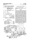
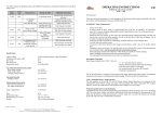
27" WALL OVEN DESCRIPTION
__2
1 1/4" Dia Conduit Access
12
Hole*
5/8" Plywood Fioor (Must Support 142 lbs)
30" WALL OVEN DESCRIPTION
DIMENSIONS
...........
..........
DIMENSIONS
in
cm
in
cm
A
27 MIN
68.58 MIN
A
30 MIN
76.20 MIN
B
24 MIN
60.96 MIN
B
24 MIN
60.96 MIN
D
O
E
23 1/2 MIN
277/16±1/16
251/2±1/16
59.69
MIN
69.69 ±.16
64.77 ±,16
D
C
E
23 1/2 MIN
277/16±1/16
283/16±1/16
59.69
MIN
69.69 ±.16
71.60 ±.16
..............
..............
F
27 3/4
70.49
F
27 3/4
70.49
.........
G
26 3/4
24 7/16
67.95
62.07
G
H
29 3/4
24 7/16
75,57
62.07
........
4to33
10.2 to83,8
I
4to33
10.2 to83.8
.........
I
I
i
!
......!
................
i
........................
S
........................
i .....
'i
"Z
...........................
...............
•
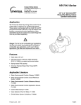
1 1/4" Dia Conduit
Access
Hole--*--
2
5/8" Plywood Floor (Must Support 250 Ibs)
1
1 1/4" Dia Conduit
2
.....
.......
...... ;
Hole*
5/8" Plywood Floor (Must Support 250 Ibs)
DIMENSIONS
......
Access
DIMENSIONS
A
in
27 MIN
cm
68.58 MIN
A
in
30 MIN
cm
76.20 MIN
B
24 MIN
60.96 MIN
B
24 MIN
60.96 MIN
C
49 5/8 4-1/16
126.05 4-.16
C
49 5/84-1/16
126.05 ±.16
D
23 1/2 MIN
59.69 MIN
D
E
25 1/24-1/16
64.77 ±.16
E
283/16±1/16
49 15/16
126.84
F
49 15/16
126.84
26 3/4
24 7/16
67,95
62.07
G
H
29 3/4
24 7/16
75.57
62.07
4 to 12
10.2 to 30.5
[
4 to 12
10.2 to 30.5
_{_E'
IJ
............
: _1
_
.................
......................
:
_
....................................................................................................................................................
...............
.................................................................
23 1/2 MIN
59,69 MIN
71.60 ±.16
......................................
UNDERCOUNTER INSTALLATION
....
_ ......
........................
i
.................
i
..........................
..........................................
!
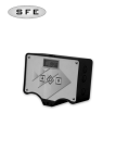
27" WALL
OVEN
1 1/4" Dia Conduit
DESCRIPTION
30" WALL
Access Hole*
1
5/8" Plywood Floor (Must Support 142 Ibs)
2
OVEN
1 1/4" Dia Conduit
DESCRIPTION
Access Hole*
5/8" Plywood Ftoor (Must Support 142 [bs)
-
i ,,l
DIMENSIONS
DIMENSIONS
............
in
cm
............
25
63.50
24 MIN
......
in
cm
A
25
63.50
60.96 MIN
B
24 MIN
60.96 MIN
27 7/16 ±1/16
23 1/2 MIN
69.69 ±.16
69.69 MIN
C
D
27 7/16 ±1/16
23 1/2 MIN
69.69 ±.16
59.69 MIN
25 1/2±1/16
27 3/4
64.77±.16
70.49
E
F
28 3/16±1/16
27 3/4
71.60 ±.16
70.49
............
..........
........
_-.
:
26 3/4
24 7/16
67.95
62.07
G
H
29 3/4
24 7/16
67.95
62.07
36
1 1/2 MIN
91.44
3.81 MIN
I
J
36
1 1/2 MIN
91.44
3.81 MIN
NOTES
NOTES
............. DO not block air intake slots along bottom
of oven
........
Gas or electric cooktops may be installed over
ovens. See cook'top installation instructions for
cutout size.
Electrical connection for electric cooktop must be
in adjacent accessible location. Cooktop and
.....
_ wall oven must be on separate 120/240 or 120/
208 volt 60 HzAC circuits.
__
** JENN-AIR
COOKTOPS
K
K
4 Burner Gas
Electric
.....
Z
Y
W
27" WALL OVEN
in
cm
2 7/8 MIN
3 1/8 MIN
7.3 MIN
7.9 MIN
Do not block air intake slots along bottom
of oven
Gas or electric cooktops may be installed over
ovens. See cook'top installation instructions for
cutout size.
Electrical connection for electric cook'top must be
in adjacent accessible location. Cooktop and
wall oven must be on separate 120/240 or 120/
208 volt 60 HzAC circuits.
.30" WALL OVEN
in
cm
-2 ii1/8 MiN
3 1/8 MIN
....
5.4 MIN
7.9 MIN
Hole must be cut as close to comer of cabinet as possible.
See Dealer for approved cooktops ....
.............
)9/R1
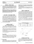
ElectricalConnections
Unit to be properlycircuit protected and wired according to
local electrical code and National Electrical Code.
It is advisable that the electrical wiring and hookuF C."'_
_
accomplished by a competent electrician.
120/240 VAC or 120/208 VAC 60 Hz. See serial plate on
front of unit for power requirements.
1. Cut hole in cabinet to mount oven. Cutout in cabinet
should be level and straight,
Note: There are no provisions to level the unit after it is
installed. An oven that is not level could cause
poor baking results,
The neutral of this unit is grounded to the frame through the
green or solid grounding wire. (The green and the white
wires are twisted together at the termination of the conduit.)
If local conditions do not permit grounding of the neutral,
untwistthe greenwire and connectthe green wireto ground
in accordance with local codes. Connect the white neutral
to the service neutral.
2. Install plywood floor as shown above.
3. Attach unit to the cabinet with four No. 8xl/2" screws
supplied with unit inside of envelope containing these
instructions. Pre-drill holes in cabinet for attachment
screws using 1/8" drill. Oven mounting holes are
The chart below recommended the minimum circuit
protection and wire size if the appliance is the only unit on
the circuit.
provided in side trim.
4. See instructionsbelow for electrical hook-up.
5
=.e User's Manual for operating instructions.
Installing Bottom Trim Piece
K.W,
RATING
ONSER_LPLATE
0- 4.8
4.9 - 6.9
7.0- 9.9
10.0- 11.9
12,0-14.9
RECOMMENDEDMINIMUM
CIRCUITPROTECTION
WlRESIZE
IN_PERS
(AWG)
20
12
_'_
30
10
40
8
50
8
60
6
Service
Interruptthesource of electricityto the unitwhen attempting
to repair or service the oven. Failure to do this could result
in a dangerous or even fatal shock.
IMPORTANT- SAVE FOR LOCAL ELECTRICALINSPECTOR'SUSE
PartNo,209630A