1
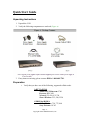
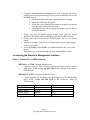
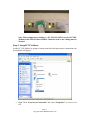
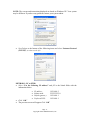
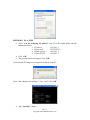
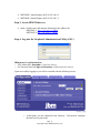
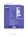
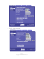
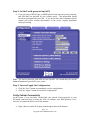
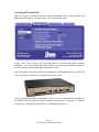
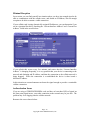
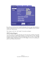
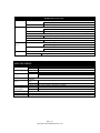
C-130
Quick Start Guide
Page -1Copyright ©2007 JBM Electronics, Inc.
Table of Contents
Quick Start Guide ............................................................................................................... 3 Unpacking Instructions ................................................................................................... 3 Preparation ...................................................................................................................... 3 Accessing the Graphical Management Interface ............................................................ 4 Step 1: Connect PC to JBM Gateway ..................................................................... 4 Step 2: Setup PC IP Address................................................................................... 5 Step 3: Access JBM Webserver .............................................................................. 8 Step 4: Log into the Graphical Administration Utility (GAU) ............................... 8 Cellular Card Configuration ........................................................................................... 9 Step 2: Set the Userid, password and APN ........................................................... 12 Step 3: Save and Apply the Configuration ........................................................... 12 Verify Cellular Connectivity......................................................................................... 12 Cellular Connectivity Troubleshooting......................................................................... 13 Cellular Reception ................................................................................................ 13 Verifying IP Connectivity ..................................................................................... 14 Minimal Reception................................................................................................ 15 Authentication Issues ............................................................................................ 15 JBM Technical Support ........................................................................................ 16 SPECIFCATIONS ............................................................................................ 17 FCC Compliance Statement .............................................................................................. 18 Information To The User .............................................................................................. 18 Warranty ........................................................................................................................... 19 Extended Warranty Program......................................................................................... 19 Page -2Copyright ©2007 JBM Electronics, Inc.
Quick Start Guide
Unpacking Instructions
1. Unpack the C130.
2. Verify the following components are enclosed (Figure A).
3. If any items are missing, please contact JBM at 1-800-489-7781.
Preparation
1. Verify that you have one of the following, supported cellular cards:
1xRTT/1xEVDO
Audiovox/UTSStarcom: 5740
Kyocera: KPC-650
Novatel: S/V-620, S/V-720
Sierra Wireless: 555, 580, 5220
GPRS/Edge/HSDPA
Sierra Wireless: 750, 775, 860
Sony Ericsson: GC-83
Page -3Copyright ©2007 JBM Electronics, Inc.
2. Using the instructions that accompanied the card, verify that the card is
properly activated and functioning correctly prior to installing the car into
the JBM Gateway:
• Install the software that came with the aircard on a laptop.
• Install the aircard into the laptop.
• Follow the carrier provided procedures to properly activate the
card, and unlock the card if necessary.
• Using the browser on the laptop insure that you are able to
browse the Internet.
3. Resolve any and all signal/reception related issues with the aircard
installed in the laptop before installing the card into the JBM Gateway.
4. Gently, insert the Aircard into the PCMCIA slot. Be sure it is firmly
seated.
5. Attach power supply connector to C130 and connect power supply plug to
an AC power outlet.
6. Verify the PWR (yellow) LED is lit to indicate that the unit is receiving
power.
7. Establish access to the unit through Gateway Administration Utility.
Accessing the Graphical Management Interface
Step 1: Connect PC to JBM Gateway
METHOD – 1 ETH0: (Straight Ethernet Port)
•
Connect a crossover CAT-5 Ethernet cable between the local PC and the
JBM unit’s ETH0. Verify the link LED is lit. (Straight cable from a
HUB/Switch).
METHOD 2 - ETH1:(Crossed-over Ethernet Port)
•
Connect straight CAT-5 Ethernet cable between the local PC and the JBM
unit’s ETH1. Verify the link LED is lit. (Crossover cable for
HUB/Switch).
Port
Straight (ETH0)
Straight (ETH0)
Crossed (ETH1)
Crossed (ETH1)
Cable
Straight
Crossed
Straight
Crossed
Device
HUB or Switch
PC
PC
HUB or Switch
Page -4Copyright ©2007 JBM Electronics, Inc.
Note: This example shows cabling to a PC. The link LED is not lit for ETH1.
Without a link LED lit either Method 1 must be used or the cabling must be
checked.
Step 2: Setup PC IP Address
Set the PC’s IP Address by going to control panel and selecting network connections, the
screen below will appear:
•
Right Click “Local Area Connection” and select “Properties” (as shown to the
left).
Page -5Copyright ©2007 JBM Electronics, Inc.
NOTE: The screens and instructions displayed are based on Windows XP. Your system
may be different. If you have any problems contact your system admin.
•
Scroll down to the bottom of the following items and select “Internet Protocol
(TCP/IP)” (as shown to the left).
METHOD 1: PC to ETH0
• Select “Use the following IP address” and fill in the blank fields with the
information below:
•
•
•
•
•
•
IP address:
Subnet mask:
Default gatewa:y
Preferred DNS:
192.168.0.2
255.255.255.0
192.168.0.1
192.168.0.1
Click “OK”
The previous screen will appear Click “OK”
Page -6Copyright ©2007 JBM Electronics, Inc.
METHOD 2: PC to ETH1
• Select “Use the following IP address” and fill in the blank fields with the
information below:
• IP address:
192.168.1.2
• Subnet mask:
255.255.255.0
• Default gatewa:y
192.168.1.1
• Preferred DNS:
192.168.1.1
• Click “OK”
• The previous screen will appear Click “OK”
Verify that the IP change was accepted or acquired on the PC.
Select “Start>Run on your desktop ” Type “cmd” Click “OK”
•
Type “ipconfig” <Enter>
Page -7Copyright ©2007 JBM Electronics, Inc.
•
•
METHOD 1 should display an IP of 192.168.0.2
METHOD 2 should display an IP of 192.168.1.2
Step 3: Access JBM Webserver
•
Open a web browser and enter the following in the address bar:
METHOD 1: http://192.168.0.1:10000/
METHOD 2: http://192.168.1.1:10000/
Step 4: Log into the Graphical Administration Utility (GAU)
JBMgateway Login Instructions
•
User Name enter: jbmadmin ( lowercase letters)
•
For Password enter: six digit serial number of unit (lowercase letters)
Upon successfully logging in you will be rewarded with the following screen:
•
At this point, you are connected to the Gateway. You can now configure
the unit to meet your needs.
Page -8Copyright ©2007 JBM Electronics, Inc.
Cellular Card Configuration
Your JBM Gateway is able to detect many cellular cards, but others must still be
configured manually. If you are using either one of the older 1xRTT/CDMA cards, or a
GPRS/EDGE/HSDPA card that requires the use of a userid, password, and APN, you will
need to configure your car manually, as covered in the next section.
If you are using any of these cards you will need to work through this section:
GPRS/Edge/HSDPA
Sierra Wireless: 750, 775, 860
Sony Ericsson: GC-83
If you are using one of the newer 1xRTT/1xEVDO, USB Serial based cards, your JBM
gateway has probably automatically detected, configured, and activated your cellular
connection for you, so you can skip this section and proceed to the next section to verify
your cellular connectivity.
If you are using any of these cards you can skip this section:
1xRTT/1xEVDO
Audiovox/UTSStarcom: 5740
Kyocera: KPC-650
Novatel: S/V-620, S/V-720
Sierra Wireless: 555, 580, 5220
Navigate through the GAU menus to the screen Cellular Configuration Screen shown
below:
Page -9Copyright ©2007 JBM Electronics, Inc.
Step 1: Cellular Carrier Selection
•
Select the cellular carrier you are using from the drop-down menu.
Page -10Copyright ©2007 JBM Electronics, Inc.
•
Select the Aircard you are using:
Page -11Copyright ©2007 JBM Electronics, Inc.
Step 2: Set the Userid, password and APN
•
If you are using a GPRS, Edge, or HSDPA based card, enter the userid, password,
and APN that was provided by your cellular carrier. This information should
have been packaged with your card. If you do not have this information please
contact your carrier account representative or the carrier’ support department
before proceeding.
Note: The userid, password, and APN are case specific. Be certain that you use the
exact information as provided by your carrier.
Step 3: Save and Apply the Configuration
•
•
Click the “Save” button to permanently save the configuration.
Click the “Apply” button to activate the configuration.
Verify Cellular Connectivity
At this point, if you previously verified that your aircard worked properly in your
PC/laptop, and have been accessing the GAU to configure your JBM gateway via its’
browser, you should be able to access the Internet.
•
Open a browser on the PC/Laptop, and attempt to browse the Internet.
Page -12Copyright ©2007 JBM Electronics, Inc.
Note: Depending on the provisioning of your card, particularly in corporate
applications in which the JBM Gateway is providing cellular backup connectivity
to wired circuits, your card may be restricted from Internet access. If this is the
case, you may want to instead test to insure that you are able to access your
corporate network. If you have any question as to your configuration please
check with your network administration.
If you were able to successfully access you’re the Internet, or your corporate network,
then congratulations, your JBM Gateway is up and running and you have successfully
completed the Quick Start. You may skip the troubleshooting section that follows.
If you were unable to access the Internet, or your corporate network, the section that
follows will help you to determine the cause of your difficulties.
Cellular Connectivity Troubleshooting
If you are reading this section, you have followed all of our instructions so far and your
JBM Gateway is not communicating. This section is intended to give you some
additional things to check in order to isolate the cause of your difficulties.
Cellular Reception
Before we get into specifics regarding how to identify and address specific problems that
can be encountered, it is important that we spend a moment talking about cellular signal
reception, and appropriate expectations.
All of the major cellular carriers expend significant sums insuring that we have excellent
signal coverage within their coverage areas. However, they have no control over the
environments in which we attempt to place or use our cellular devices.
The principles behind cellular data reception are similar to cellular phone reception.
Therefore, our environment has the potential to significantly impact our ability to receive
a good quality cellular signal.
You should be aware that it is possible to stand in the parking lot of a building and have
perfect reception, but walk just 10 feet inside a concrete and steel building and have
absolutely no reception at all.
The important thing to understand here is that in many, many instances it is not the
cellular network that causes us reception problems, but the environment in which we
place our cellular devices.
For this reason, JBM Electronics strongly recommends the use of external antennas
when implementing cellular data. It can make the difference between an implementation
that works and one that doesn’t.
Page -13Copyright ©2007 JBM Electronics, Inc.
Verifying IP Connectivity
First, let’s check to make sure that you card is connecting to the cellular network and
obtaining an IP address. Navigate to the GAU screen shown below:
If your screen looks similar to the one shown above, you are having signal reception
difficulties. As you will notice, the card is neither connected to the cellular network, nor
has it been able to obtain an IP address from the network.
You can further verify this condition by examining the LED signal meter on the left side
of the front panel of the device as shown in the picture below:
If the top and bottom LEDs are flashing the device is not receiving sufficient signal from
the cellular towers in order to be able to connect to the network. Typically, 2-3 LEDs of
reception are a minimum requirement for a sustainable connection.
Page -14Copyright ©2007 JBM Electronics, Inc.
Minimal Reception
On occasion, you can find yourself in a situation where you have just enough signal to be
able to communicate with the cellular tower, and obtain an IP address, but not enough
reception to be able to sustain a viable connection.
If your cellular card is using dynamically assigned IP addresses, you can determine if you
are in a situation like this by watching the “Current Interface Address” and “Current Peer
Address” fields in the screen below:
If you refresh this screen every few minutes and notice that the “Current Interface
Address” is changing frequently, it is very possible that your device is connecting to the
network and obtaining and IP address, and then the connection to the cellular network is
being dropped. When the connection is re-established the device is then issued a
different IP address.
In this situation an external antenna can boost the signal enough to provide a sustainable
cellular connection.
Authentication Issues
If you are using a GPRS/EDGE/HSDPA card, and have at least three LEDs of signal on
the front panel signal meter, your radio connection to the network may be just fine. The
problem may lie in logging onto the cellular network.
Return to the screen shown below:
Page -15Copyright ©2007 JBM Electronics, Inc.
Re-verify your userid, password, and APN information. Be sure to pay close attention, as
all three of these items are case specific and must be entered exactly in order to properly
log into the cellular network.
Don’t forget to click “Save” and “Apply” if you make any changes.
JBM Technical Support
If you have followed all of the instructions up to this point, have satisfied yourself that
you are not having an authentication problem, are convinced that you have sufficient
reception, and your gateway is still not communicating, then it is time to contact JBM
Technical Support at 800-489-7781 and we will be happy to assist you in getting your
gateway up, running, and operational.
Page -16Copyright ©2007 JBM Electronics, Inc.
HARDWARE STATUS LEDS
Power:
Yellow – Power Connection Status (PWR)
ON
Power is being received by the C130
OFF
Power is not being received by the C130
Ethernet Ports:
Green – LAN Connection Status (LINK)
ON
C130 is connected to LAN
OFF
C130 is not connected to the LAN, or the C130 is in the process of being reset
RED – Data Transmit Activity Status (T)
ON-OFF-ON (Flickering)
C130 is transmitting packets
Green – Data Receive Activity Status (R)
ON-OFF-ON (Flickering)
C130 is receiving packets
RS232 Ports:
(Async)
Green – Data Receive Activity Status (RD)
ON-OFF-ON (Flickering)
C130 is receiving packets
Red – Data Transmit Activity Status (TD)
ON-OFF-ON (Flickering)
C130 is transmitting packets
Card Bus:
Yellow – Activity (ACT)
ON
Card negotiation with Bus in C130
SPECIFCATIONS
Console Port:
Ethernet Ports:
RS232 Ports:
(Async)
RS232C Port:
(Sync)
Card Bus:
Operating System:
Management:
Power:
Physical:
Baud Rate:
Interface:
Mbps:
Interface:
Interface:
110-115,200 bps
One Female DB-9, RS-232C DCE
10/100BaseT
Two Female RJ-45 connectors
Type II Connector, 3.3V or 5V, 16 bit PC Cards or 32 bit Card Bus
Linux 2.6 Kernel
Console
CLI Access through async connection
Port:
IP Protocol
SNMP, HTTP/S, Telnet, SSH
12V DC (External) 120 VAC 60Hz or 120-240 VAC 50/60Hz
Size:
7” W x 2.5” H x 8” L
Weight:
2 pounds
486DX-100
32 MB RAM, 16MB Flash
1 Year Parts and Labor
Page -17Copyright ©2007 JBM Electronics, Inc.
Software Licensing Terms and Conditions
Software supplied with each JBM Electronics' product remains the exclusive property of
JBM Electronics. JBM grants with each unit a perpetual license to use this software with
the express limitation that the software may not be copied or used in any other product
for any purpose. It may not be reverse engineered, or used for any other purpose other
than in and with the computer hardware sold by JBM Electronics.
FCC Compliance Statement
This equipment has been tested and found to comply with the limits for a Class A digital
device, pursuant to part 15 of the FCC rules.
These limits are designed to provide reasonable protection against harmful interference
when the equipment is operated in a commercial environment.
This equipment generates, uses and can radiate radio frequency energy; and if not
installed and used in accordance with the instructions, may cause harmful interference to
radio communications.
Operation of this equipment in a residential area is likely to cause harmful interference to
radio communications, in which case the user will be required to correct the interference
at their own expense.
Warning: Changes or modifications to this unit not expressly approved by the party
responsible for compliance could void the user’s authority to operate the equipment.
Information To The User
If this equipment causes interference to radio or television reception, which can be
determined by turning the equipment off and on, the user is encouraged to try to correct
the interference by one or more of the following measures:
In order to meet FCC emissions limits, this equipment must be used only with cables that
comply with IEEE 802.3
If necessary, the user should consult the dealer or an experienced radio/television
technician for additional suggestions.
The user may find the following booklet prepared by the Federal Communications
Commission helpful: “How to Identify and Resolve Radio-TV Interference Problems”.
This booklet is available from:
U.S. Government Printing Office
Washington, DC 20402
Stock No. 004-000-00345-4
Page -18Copyright ©2007 JBM Electronics, Inc.
Warranty
JBM Electronics provides a limited hardware warranty for the Gateway, which consists
of the following:
•
•
•
•
•
This warranty is effective for one year from the delivery date of the Gateway to the
purchaser.
The purchaser is responsible for returning the defective unit to our factory, freight
prepaid.
If the Gateway is under warranty, we will repair it at our cost and return it, freight
prepaid, via UPS ground service.
If the Gateway is not covered by the warranty, we will notify you of the repair charges.
We will not repair the Gateway without your permission.
Repairs are guaranteed for 90 days or the remainder of the warranty, whichever is longer.
Buyer's remedies for breach of warranty shall be limited to repair or replacement subject
to adjustment as stated herein, or full or partial adjustment to purchase price.
The JBM Electronics Gateways are provided with the following warranty:
1. Hardware maintenance and repair is available on a return to factory basis.
2. Configuration assistance is included for the first 60 days after the initial contact to JBM
Technical support. After this initial period, configuration assistance will continue to be available
on a chargeable basis.
3. Software support does not provide for custom code. Custom changes are available as a
chargeable option.
4. The warranty only covers items with a serial number. Cables and adapters are not covered.
Extended Warranty Program
JBM offers an extended warranty for the Gateway. This program extends the original
warranty on a yearly basis. In addition to extending the original warranty, the emergency
replacement program is included for the cost of freight only.
The extension must be purchased before the original warranty expires. Please contact
JBM Electronics for further information
Except for the express warranty set forth herein, JBM Electronics Co. grants no
warranties, either express or implied, of merchantability and fitness. The stated express
warranty is in lieu of all liabilities or obligations of JBM Electronics Co. for damages
including but not limited to consequential damages occurring out of or in connection with
the delivery, use or performance of JBM products.
Page -19Copyright ©2007 JBM Electronics, Inc.