1
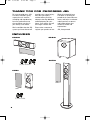
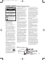
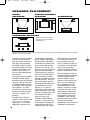
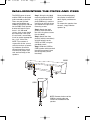
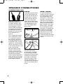
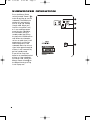
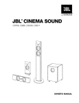
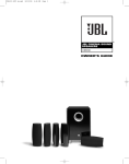
CS OM
5/16/06
9:24 AM
Page 1
JBL CINEMA
SOUND™
®
CST55, CSB5, CSC55,
CSS10
OWNER’S GUIDE
CS OM
5/16/06
9:24 AM
Page 2
THANK YOU FOR CHOOSING JBL
For more than 60 years, JBL
has been involved in every
aspect of music and film
recording and reproduction,
from live performances to
the recordings you play in
your home, car or office.
provide every note of enjoyment that you expect –
and that when you think
about purchasing additional
audio equipment for your
home, car or office, you will
once again choose JBL.
We’re confident that the JBL
system you have chosen will
Please take a moment to
register your product on our
Web site at www.jbl.com.
It enables us to keep you
posted on our latest advancements, and helps us to better
understand our customers
and build products that
meet their needs and
expectations.
JBL, Incorporated
INCLUDED
CSC55
CSS10
Grille
CST55
(2) Wall brackets
CSB5
Grille
Grille
(1) Wall bracket
2
CS OM
5/16/06
9:24 AM
Page 3
READ FIRST! Important Safety Precautions!
CAUTION
RISK OF ELECTRIC SHOCK
DO NOT OPEN
CAUTION: To reduce the risk of electric shock,
do not remove cover (or back).
No user-serviceable parts inside.
Refer servicing to qualified service personnel.
CAUTION: To prevent electric shock,
do not use this (polarized) plug with
an extension cord, receptacle or other outlet
unless the blades can be fully inserted to
prevent blade exposure.
The lightning flash with arrowhead symbol,
within an equilateral triangle, is intended to
alert the user to the presence of uninsulated
“dangerous voltage” within the product’s
enclosure that may be of sufficient magnitude to constitute
a risk of electric shock to persons.
The exclamation point within an equilateral
triangle is intended to alert the user to the
presence of important operating and
maintenance (servicing) instructions in the
literature accompanying the appliance.
1. Read these instructions.
2. Keep these instructions.
3. Heed all warnings.
4. Follow all instructions.
5. Do not use this apparatus near
water.
6. Clean only with a dry cloth.
7. Do not block any ventilation
openings. Install in accordance with
the manufacturer’s instructions.
8. Do not install near any heat
sources such as radiators, heat
registers, stoves or other apparatus
(including amplifiers) that produce
heat.
9. Do not defeat the safety purpose
of the polarized or grounding-type
plug. A polarized plug has two
blades with one wider than the
other. A grounding-type plug has
two blades and a third grounding
prong. The wide blade or the third
prong are provided for your safety.
If the provided plug does not fit into
your outlet, consult an electrician
for replacement of the obsolete
outlet.
10. Protect the power cord from
being walked on or pinched, particularly at plugs, convenience receptacles and the point where they exit
from the apparatus.
11. Only use attachments/accessories specified by the manufacturer.
12. Use only with the cart, stand,
tripod, bracket or table specified by
the manufacturer or sold
with the apparatus.
When a cart is used,
use caution when moving
the cart/apparatus combination to
avoid injury from tip-over.
13. Unplug this apparatus during
lightning storms or when unused for
long periods of time.
14. Refer all servicing to qualified
service personnel. Servicing is
required when the apparatus has
been damaged in any way, such
as power-supply cord or plug is
damaged, liquid has been spilled
or objects have fallen into the
apparatus, the apparatus has been
exposed to rain or moisture, does
not operate normally, or has been
dropped.
15. Do not use attachments not
recommended by the product
manufacturer, as they may cause
hazards.
16. This product should be operated
only from the type of power source
indicated on the marking label. If
you are not sure of the type of
power supply to your home, consult
your product dealer or local power
company. For products intended to
operate from battery power or other
sources, refer to the operating
instructions.
17. If an outside antenna or cable
system is connected to the product,
be sure the antenna or cable system is grounded so as to provide
some protection against voltage
surges and built-up static charges.
Article 810 of the National
Electrical Code, ANSI/NFPA 70,
provides information with regard to
proper grounding of the mast and
supporting structure, grounding of
the lead-in wire to an antenna
discharge unit, size of grounding
conductors, location of antennadischarge unit, connection to
grounding electrodes, and requirements for the grounding electrode.
See Figure A.
18. An outside antenna system
should not be located in the vicinity
of overhead power lines or other
electric light or power circuits, or
where it can fall into such power
lines or circuits. When installing an
outside antenna system, extreme
care should be taken to keep from
touching such power lines or circuits,
as contact with them might be fatal.
19. Do not overload wall outlets,
extension cords, or integral
convenience receptacles, as this
can result in a risk of fire or
electric shock.
20. Never push objects of any kind
into this product through openings,
as they may touch dangerous voltage points or short-out parts, which
could result in a fire or electric
shock. Never spill liquid of any kind
on the product.
21. The apparatus shall not be
exposed to dripping or splashing,
and no objects filled with liquids,
such as vases, shall be placed on
the apparatus.
22. Do not attempt to service this
product yourself, as opening or
removing covers may expose you to
dangerous voltage or other hazards.
Refer all servicing to qualified
service personnel.
23. When replacement parts are
required, be sure the service technician has used replacement parts
specified by the manufacturer or
that have the same characteristics
as the original part. Unauthorized
substitutions may result in fire,
electric shock or other hazards.
24. Upon completion of any service
or repairs to this product, ask the
service technician to perform safety
checks to determine that the product is in proper operating condition.
25. The product should be mounted
to a wall or ceiling only as recommended by the manufacturer.
Figure A.
Example of Antenna Grounding as per
National Electrical Code ANSI/NFPA 70
3
CS OM
5/16/06
9:24 AM
Page 4
SPEAKER PLACEMENT
FRONT
SPEAKERS
CENTER CHANNEL
SPEAKER
SUBWOOFER
0–2 ft
0–0.6m
SURROUND SPEAKERS
† Single surround back speaker
may be used with 6.1 receivers
and processors.
Alternate placement for surround speakers when only 5.1 channels are used; required placement for surround back
speakers in 7.1-channel systems.
The front speakers should be
placed the same distance
from each other as they are
from the listening position.
The CSB5 speakers should
be placed at about the same
height from the floor as the
listeners’ ears will be, or
they may be angled toward
the listeners.
The center channel speaker
should be placed slightly
behind the front left and right
speakers, and no more than
2 feet (0.6m) above or below
the tweeters of the left and
right speakers. It is often
convenient to set the center
speaker on top of the television set, as shown in the
drawing.
The JBL Cinema Sound
speaker system may be used
in 5.1-, 6.1- or 7.1-channel
applications. In 5.1-channel
applications, two of the sur4
round speakers should be
placed slightly behind the listening position and, ideally,
should face each other and
be at a level higher than the
listeners’ ears. If that is not
possible, they may be placed
against a wall behind the
listening position, facing forward. In 6.1-channel applications, two of the surround
speakers should be placed in
the side positions, and a single surround back speaker
should be placed against the
wall behind the listening
position. In 7.1-channel
applications, place two of the
surround speakers in the side
positions, and place the two
surround back speakers
against the rear wall.
In Dolby® Digital and DTS®
systems, it is best to aim all
of the speakers (except the
subwoofer) toward the listening position at or slightly
above about ear-level height.
In systems where only analog surround processing
(such as Dolby Pro Logic® II)
is available, it may be preferable to aim the speakers
straight out from the wall to
obtain a more diffuse sound.
The low-frequency material
reproduced by the subwoofer
is mostly omnidirectional,
and this speaker may be
placed in a convenient location in the room. However,
bass reproduction will be
maximized when the subwoofer is placed in a corner
along the same wall as the
front speakers. Experiment
with subwoofer placement
by temporarily placing the
subwoofer in the listening
position and moving around
the room until the bass
reproduction is best. Place the
subwoofer in that location.
CS OM
5/16/06
9:24 AM
Page 5
WALL-MOUNTING THE CSC55 AND CSB5
The CSC55 center channel
and the CSB5 are designed
to be mounted on the wall.
There are two (2) fixedmount wall brackets provided for the CSC55, and one
for the CSB5. Each speaker
bracket will require up to
three 1-1/2" #10 wood
screws; each screw should
be fastened to a wall stud.
If a wall stud is unavailable,
install an anchor appropriate
for a 1-1/2" #10 screw.
NOTE: The customer is
responsible for the correct
selection and use of mounting hardware (available
through hardware stores)
to ensure the proper and
safe wall-mounting of the
speakers.
Step 1. Using the included
mounting template (CSC55
only) or the bracket back
plate (CSB5 only), mark the
positions on the wall where
you would like to place the
mounting screws.
Once positioned properly,
the speaker should slide
down slightly and become
secure.
To remove the speaker from
the wall, simply slide the
speaker up.
Step 2. Attach the back
plate(s) of the bracket to
the wall using three screws
(not included).
Step 3. Attach the front
plate(s) (with the two holes)
of the bracket(s) to the
CSC55 or CSB5, using the
provided screws.
Step 4. Slide the CSC55 or
CSB5 speaker with attached
bracket front plate(s) onto
the back plate(s) of the
bracket(s).
CSC55
CSB5
NOTE: Remove the base of the
CSB5 by removing the two
screws on the bottom of the
speaker.
5
CS OM
5/16/06
9:24 AM
Page 6
SPEAKER CONNECTIONS
CONNECTION TIPS
Separate and strip the
ends of the speaker wire
as shown. Speakers and
electronics terminals have
corresponding (+) and (–)
terminals. Most manufacturers
of speakers and electronics,
including JBL, use red to
denote the (+) terminal and
black to denote the (–)
terminal.
CST55
CSB5, CSC55
To provide a neater installation, the CST55 allows you
to insert the speaker wires
through holes in the base.
To use the binding-post
speaker terminals, unscrew
the colored collar until the
pass-through hole in the
center post is visible under
the collar. Insert the bare
end of the wire through this
hole; then screw the collar
down until the connection is
tight. The hole in the center
of each collar is intended
for use with banana-type
connectors. To comply with
European CE certification,
these holes are blocked
with plastic inserts at the
point of manufacture. To
use banana-type connectors
requires the removal of the
inserts.
Simply separate and strip
the wires as described
above, loosen the terminals
and insert each wire into its
corresponding hole in the
base. Then tighten down
the terminals.
The (+) lead of the speaker
wire is noted with a stripe.
It is important to connect
both speakers identically:
(+) on the speaker to (+) on
the amplifier and (–) on the
speaker to (–) on the amplifier.
Wiring “out of phase”results
in thin sound, weak bass and
a poor stereo image.
With the advent of multichannel surround sound
systems, connecting all of
the speakers in your system
with the correct polarity
remains equally important in
order to preserve the proper
ambience and directionality
of the program material.
6
The hole in the center
of each collar is intended
for use with banana-type
connectors. To comply with
European CE certification,
these holes are blocked
with plastic inserts at the
point of manufacture. To
use banana-type connectors
requires the removal of the
inserts.
CS OM
5/16/06
9:24 AM
Page 7
DOLBY® DIGITAL OR DTS®
(OR OTHER DIGITAL SURROUND MODE) CONNECTION
frequency effects channel.
Connect this jack to the LFE
output or subwoofer output
on your receiver or amplifier.
Connect each speaker to
the corresponding speaker
terminals on your receiver
or amplifier.
SUBWOOFER
RECEIVER
L
LINE LFE
LEVEL
IN
LFE OUT
R
Use this installation method
for Dolby Digital, DTS or
other digital surround
processors:
Make sure that you have
configured your surround
sound processor for “Subwoofer On.” Also configure
Use the line-level input jack
marked “LFE” for the low-
your receiver for 5.1-, 6.1or 7.1-channel operation, as
appropriate. The front left,
front right, center and rear
speakers should all be set
to “Small.” If your receiver
allows you to set the crossover frequency between the
subwoofer and the main
speakers, select 100Hz or
the setting that is the closest
frequency below it.
DOLBY PRO LOGIC® (NON-DIGITAL) – LINE LEVEL
Use this installation method
for Dolby Pro Logic applications (not Dolby Digital, DTS
or other digital processing),
where the receiver/processor is equipped with a subwoofer output, or a volumecontrolled preamp (line-)
level output:
Center
Left Front
–
Use RCA-type interconnects
to connect the line-level
subwoofer outputs on your
receiver or amplifier to the
line-level inputs on the subwoofer. IMPORTANT: Do not
use the LFE input on the subwoofer with Dolby Pro Logic
processors.
–
+
Right Front
+
–
+
Subwoofer
Line
Level In
Connect each speaker to
the corresponding speaker
terminals on your receiver
or amplifier.
L
R
Receiver
Subwoofer
Out
Left
Front
–
–
+
Left
Surround
Left Surround
–
+
–
+
R
+
Surround Back
Left
–
+
Make sure your receiver or
processor is correctly configured to indicate that the
subwoofer is “On.”
Right
Front
+
–
L
+
Center
Surround Back
Surround Back
Right
Left
–
NOTE: If your receiver or
amplifier has only one subwoofer output jack, then you
will need to use a Y-connector
(not included). Plug the male
end of the Y-connector into
your receiver or amplifier’s
subwoofer output jack, and
connect each of the two
female ends to separate
RCA-type interconnects.
Finally, plug the RCA-type
interconnects into the linelevel inputs on the subwoofer.
–
+
Surround Back
Right
–
+
–
+
Right
Surround
Right Surround
–
+
7
CS OM
5/16/06
9:24 AM
Page 8
SUBWOOFER OPERATION
Press the Master Power
switch (marked “Power” å)
to the On position to use the
subwoofer. The CSS10 subwoofer will automatically
turn on or go into standby
(sleep) mode. When your
receiver or amplifier is off,
or is not sending program
material to the subwoofer,
the subwoofer will be in
standby mode (the LED on
the front of the CSS10 will be
red). When the subwoofer
senses an audio signal, it will
automatically turn on (the
LED will be green). If the
subwoofer does not sense a
signal after approximately 20
minutes, it will automatically
go into standby mode.
If you will be away from
home for an extended period
of time, or if the subwoofer
will not be used, switch the
Master Power switch å to
the Off position by pressing
it until it pops out.
8
CS OM
5/16/06
9:24 AM
Page 9
VOLUME
Subwoofer
Level
MIN
MAX
Subwoofer
Level
MIN
MAX
Volume may be adjusted
using the Subwoofer Level
control ∫, as shown.
The Phase control determines whether the subwoofer’s pistonlike action
moves in and out in phase
with the main speakers or
opposite the main speakers.
There is no correct or incorrect setting. Proper phase
adjustment depends on several variables, such as subwoofer placement and listener position. Adjust the
Phase switch ç to maximize bass output at the
listening position.
Remember, every system,
room and listener is different. There are no right or
wrong settings; this switch
offers the added flexibility to
adjust your subwoofer for
optimum performance for
your specific listening conditions without having to move
your speakers. If at some
time in the future you happen to rearrange your listening room and move your
speakers, you should experiment with the phase switch
in both positions, and leave
it in the position that maximizes bass performance.
9
CS OM
5/16/06
9:24 AM
Page 10
TROUBLESHOOTING
If there is no sound from any
of the speakers:
• Check that receiver/amplifier is on and a source is
playing.
• Check that the powered
subwoofer is plugged in
and is turned on (Power
switch å pushed in).
• Check all wires and connections between receiver/
amplifier and speakers. Make
sure all wires are connected.
Make sure none of the
speaker wires are frayed, cut
or punctured, or touching
each other.
• Review proper operation of
your receiver/amplifier.
If there is no sound coming
from one speaker:
• Check the “Balance” control
on your receiver/amplifier.
• Check all wires and connections between receiver/
amplifier and speakers. Make
sure all wires are connected.
Make sure none of the speaker
wires are frayed, cut or punctured, or touching each
other.
• In Dolby Digital or DTS
modes, make sure that the
receiver/amplifier is configured so that the speaker in
question is enabled.
• Turn off all electronics
and switch the speaker in
question with one of the
other speakers that is working correctly. Turn everything
back on, and determine
whether the problem has followed the speaker or has
remained in the same channel. If the problem is in the
same channel, the source
of the problem is most likely
with your receiver or amplifier, and you should consult
the owner’s manual for that
product for further informa10
tion. If the problem has followed the speaker, consult
your dealer for further assistance or, if that is not possible, visit www.jbl.com.
If there is no sound from the
center speaker:
• Check all wires and connections between receiver/
amplifier and speaker. Make
sure all wires are connected.
Make sure none of the
speaker wires are frayed, cut
or punctured, or touching
each other.
• If your receiver/processor
is set in Dolby Pro Logic mode,
make sure the center speaker
is not in phantom mode.
• If your receiver/processor
is set in one of the Dolby
Digital or DTS modes, make
sure the receiver/processor
is configured so that the
center speaker is enabled.
If the system plays at low
volumes but shuts off as
volume is increased:
• Check all wires and connections between receiver/
processor and speakers.
Make sure all wires are connected. Make sure none of
the speaker wires are
frayed, cut or punctured, or
touching each other.
• If more than one pair of
main speakers is being used,
check the minimum impedance requirements of your
receiver/amplifier.
If there is low (or no) bass
output:
• Make sure the connections
to the left and right “Speaker
Inputs” have the correct
polarity (+ and –).
• Make sure the subwoofer
is plugged into an active
electrical outlet and is
turned on (Power switch
å pushed in).
• In Dolby Digital or DTS
modes, make sure your
receiver/processor is configured so that the subwoofer
and LFE output are enabled.
• Switch the Phase switch
ç to the opposite position,
and select the position that
results in the most pleasing
bass response.
If there is no sound from
the surround speakers:
• Check all wires and connections between receiver/
processor and speakers.
Make sure all wires are connected. Make sure none of
the speaker wires are
frayed, cut or punctured, or
touching each other.
• Review proper operation of
your receiver/amplifier and
its surround sound features.
• Make sure the movie or
TV show you are watching
is recorded in a surround
sound mode. If it is not,
check to see whether your
receiver/processor has other
surround modes you may use.
• In Dolby Digital or DTS
modes, make sure your
receiver/processor is configured so that the surround
speakers are enabled. When
five satellites are in use,
remember to configure your
receiver or processor for
6.1-channel operation, and
when six satellites are in use,
configure your receiver or
processor for 7.1 channels.
• Review the operation of
your DVD player and the
jacket of your DVD to make
sure that the DVD features
the desired Dolby Digital or
DTS mode, and that you
have properly selected that
mode using both the DVD
player’s menu and the DVD
disc‘s menu.
CS OM
5/16/06
9:24 AM
Page 11
SPECIFICATIONS
System
CSC55
Frequency Response
27Hz – 30kHz (–6dB)
Maximum Recommended Amplifier Power
150 Watts*
Power Handling 50W continuous/300W peak
Frequency Response 55Hz – 30kHz (–6dB)
Nominal Impedance 8 Ohms
Sensitivity 90dB @ 1 watt/1 meter
Tweeter
3/4" (19mm) Titanium-laminate dome,
video-shielded
Woofers
Dual 5" (130mm) transducers with PolyPlas™
cones, neodymium magnets and HeatScape™
motor structure, video-shielded
Dimensions (H x W x D)
(including wall-mount bracket and grille)
6-1/4" x 26-1/4" x 4-1/4" (159mm x 667mm x 108mm)
Weight 10 lb (4.5kg)
CST55
Maximum Recommended Amplifier Power
150 Watts*
Power Handling 50W continuous/300W peak
Frequency Response 55Hz – 30kHz (–6dB)
Nominal Impedance 8 Ohms
Sensitivity 90dB @ 1 watt/1 meter
Tweeter
3/4" (19mm) Titanium-laminate dome,
video-shielded
Woofers
Dual 5" (130mm) transducers with PolyPlas™
cones, neodymium magnets and HeatScape™
motor structure, video-shielded
Dimensions (H x W x D)
(including base and grille)
46" x 11-1/4" x 11-1/4" (1168mm x 286mm x 286mm)
Weight 17 lb (7.7kg)
CSB5
Maximum Recommended Amplifier Power
125 Watts*
Power Handling 40W continuous/300W peak
Frequency Response 60Hz – 30kHz (–6dB)
Nominal Impedance 8 Ohms
Sensitivity 88dB @ 1 watt/1 meter
Tweeter
3/4" (19mm) Titanium-laminate dome,
video-shielded
Woofer
5" (130mm) Transducer with PolyPlas™ cone,
neodymium magnet and HeatScape™ motor
structure, video-shielded
Dimensions (H x W x D)
(including base and grille)
14-5/16" x 6-1/8" x 4-9/16"
(363mm x 155mm x 116mm)
Weight 5 lb (2.3kg)
Dimensions (H x W x D)
(without base and with wall-mount bracket
and grille)
13-5/16" x 6-1/8" x 5-1/8"
(338mm x 155mm x 130mm)
Weight 4.5 lb (2kg)
CSS10
Amplifier Power 150 Watts RMS
Frequency Response 27Hz – Low-pass
crossover setting at signal source
Low-Frequency Driver
10" (250mm) Cone and HeatScape™
motor structure, video-shielded
Input LFE preamp level
Dimensions (H x W x D) (including feet)
18-1/4" x 13-1/4" x 16"
(464mm x 337mm x 406mm)
Weight 43 lb (19.5kg)
All features and specifications are subject to change
without notice.
Dolby and Pro Logic are registered trademarks of
Dolby Laboratories.
DTS is a registered trademark of DTS, Inc.
* The maximum recommended amplifier power rating will
ensure proper system headroom to allow for occasional
peaks. We do not recommend sustained operation at
these maximum power levels.
11
CS OM
5/16/06
9:24 AM
Page 12
CSS10 (230V only)
Declaration of Conformity
We, Harman Consumer Group International
2, route de Tours
72500 Château du Loir
France
declare in own responsibility that the product described in this
owner’s manual is in compliance with technical standards:
EN 55013:2001+A1:2003
EN 55020:2002+A1:2003
EN 61000-3-2:2000
EN 61000-3-3:1995+A1:2001
EN 60065:2002
Laurent Rault
Harman Consumer Group International
Château du Loir, France 5/06
CSB5, CSC55, CST55
Declaration of Conformity
We, Harman Consumer Group International
2, route de Tours
72500 Château du Loir
France
declare in own responsibility that the products described in this
owner’s manual are in compliance with technical standards:
EN 61000-6-3:2001
EN 61000-6-1:2001
Laurent Rault
Harman Consumer Group International
Château du Loir, France 5/06
PRO SOUND COMES HOME™
®
JBL, Incorporated,
250 Crossways Park Drive, Woodbury, NY 11797 USA
8500 Balboa Boulevard, Northridge, CA 91329 USA
2, route de Tours, 72500 Château du Loir, France
516.255.4JBL (4525) (USA only) www.jbl.com
© 2006 Harman International Industries, Incorporated. All rights reserved.
JBL and Harman International are trademarks of Harman International Industries, Incorporated, registered in the
United States and/or other countries. JBL Cinema Sound, PolyPlas, HeatScape and Pro Sound Comes Home are
trademarks of Harman International Industries, Incorporated.
Part No. 406-000-05331-E