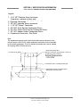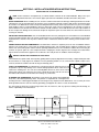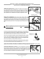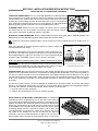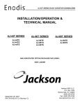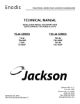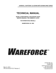
1
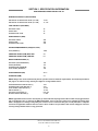
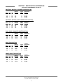
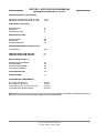
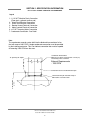
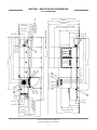
RACKLESS CONVEYOR FLIGHT TYPE DISHMACHINE SERIES
(ELECTRICALLY & STEAM HEATED)
TECHNICAL MANUAL
FOR JACKSON MODEL:
JFT
JFT-S
Jahuary 02, 2008
P/N 7610-002-77-38 (Revision E)
JACKSON MSC LLC.
P.O. BOX 1060
BARBOURVILLE, KY. 40906
PHONE: 1-606-523-9795
FAX: 1-606-523-9196
www.jacksonmsc.com
MANUFACTURERS WARRANTY
ONE YEAR LIMITED PARTS & LABOR WARRANTY
ALL NEW JACKSON DISHWASHERS ARE WARRANTED TO THE ORIGINAL PURCHASER TO BE FREE FROM
DEFECTS IN MATERIAL OR WORKMANSHIP, UNDER NORMAL USE AND OPERATION FOR A PERIOD OF (1) ONE
YEAR FROM THE DATE OF PURCHASE, BUT IN NO EVENT TO EXCEED (18) EIGHTEEN MONTHS FROM THE DATE
OF SHIPMENT FROM THE FACTORY.
Jackson MSC agrees under this warranty to repair or replace , at its discretion, any original part which fails under normal use due to faulty
material or workmanship during the warranty period, providing the equipment has been unaltered, and has been properly installed, maintained and operated in accordance with the applicable factory instruction manual furnished with the machine and the failure is reported to
the authorized service agency within the warranty period. This includes the use of factory specified genuine replacement parts, purchased
directly from a Jackson authorized parts distributor or service agency. Use of generic replacement parts may create a hazard and void warranty certification.
The labor to repair or replace such failed part will be paid by Jackson MSC, within the continental United States, Hawaii and Canada, during
the warranty period provided a Jackson MSC authorized service agency, or those having prior authorization from the factory, performs the
service. Any repair work by persons other than a Jackson MSC authorized service agency is the sole responsibility of the customer. Labor
coverage is limited to regular hourly rates, overtime premiums and emergency service charges will not be paid by Jackson MSC.
Accessory components not installed by the factory carry a (1) one year parts warranty only. Accessory components such as table limit switches, pressure regulators, pre rinse units, etc. that are shipped with the unit and installed at the site are included. Labor to repair or replace
these components is not covered by Jackson MSC.
This warranty is void if failure is a direct result from shipping, handling, fire, water, accident, misuse, acts of god, attempted repair by unauthorized persons, improper installation, if serial number has been removed or altered, or if unit is used for purpose other than it was originally intended.
TRAVEL LIMITATIONS
Jackson MSC limits warranty travel time to (2) two hours and mileage to (100) one hundred miles. Jackson MSC will not pay for travel time
and mileage that exceeds this, or any fees such as those for air or boat travel without prior authorization.
WARRANTY REGISTRATION CARD
The warranty registration card supplied with the machine must be returned to Jackson MSC within 30 days to validate the warranty.
REPLACEMENT PARTS WARRANTY
Jackson replacement parts are warranted for a period of 90 days from the date of installation or 180 days from the date of shipment from the
factory, which ever occurs first.
PRODUCT CHANGES AND UPDATES
Jackson MSC reserves the right to make changes in design and specification of any equipment as engineering or necessity requires.
THIS IS THE ENTIRE AND ONLY WARRANTY OF JACKSON MSC. JACKSON’S LIABILITY ON ANY CLAIM OF ANY KIND, INCLUDING
NEGLIGENCE, WITH RESPECT TO THE GOODS OR SERVICES COVERED HEREUNDER, SHALL IN NO CASE EXCEED THE PRICE
OF THE GOODS OR SERVICES OR PART THEREOF WHICH GIVES RISE TO THE CLAIM.
THERE ARE NO WARRANTIES, EXPRESSED OR IMPLIED, INCLUDING FOR FITNESS OR MERCHANTABILITY, THAT ARE NOT SET
FORTH HEREIN, OR THAT EXTEND BEYOND THE DURATION HEREOF. UNDER NO CIRCUMSTANCES WILL JACKSON MSC BE
LIABLE FOR ANY LOSS OR DAMAGE, DIRECT OR CONSEQUENTIAL, OR FOR THE DAMAGES IN THE NATURE OF PENALTIES,
ARISING OUT OF THE USE OR INABILITY TO USE ANY OF ITS PRODUCTS.
ITEMS NOT COVERED
This warranty does not cover cleaning or deliming of the unit or any component such as, but not limited to, wash arms, rinse arms or strainers at anytime. Nor does it cover adjustments such as, but not limited to timer cams, thermostats or doors, beyond 30 days from the date
of installation. In addition, the warranty will only cover the replacement of wear items such as curtains, drain balls, door guides or gaskets
during the first 30 days after installation. Also, not covered are conditions caused by the use of incorrect (non-Commercial) grade detergents,
incorrect water temperature or pressure, or hard water conditions.
2
STOP!
PARE!
ARRET!
CALL 1-888-800-5672 TO REGISTER THIS PRODUCT!
FAILURE TO DO SO WILL VOID THE WARRANTY!
LLAME AL 1-888-800-5672 PARA REGISTRAR ESTE PRODUCTO!
AL NO HACERLO LA GARANTIA SERA ANULADA!
S.V.P. APPELER 1-888-800-5672 POUR ENREGISTRER CE PRODUIT,
LA GARANTIE SERA ANNULEE POUR TOUT PRODUIT NON- ENREGISTREE
3
REVISION/
PAGE
REVISION
DATE
C
04-30-04
D
12-16-04
MADE APPLICABLE
BY
ECN
DETAILS
N/A
Updated to new format; Added missing parts to steam booster
assembly.
MAW
7144, 7143
7145, 7156
Added new tall door assembly parts. Added stop brackets to
unloader stop assembly. Added keys and set screws for gears.
Changed number for back strainer support. Changed drain handle
number. Changed manifold, rinse arm and plumbing assemblies
to reflect new design. Added the short door assemblies. Corrected
number for switches on load end asm. Changed drawing for belt
assembly. Added unload end assembly plumbing. Updated
schematic to revsion B. Added 600V machines.
Added spacer gaskets. Replaced level control parts with swing
arm sensor. Added final rinse arm assembly for no pump final
rinse units. Added service numbers for motor assemblies. Added
new screws for door guides. Added regulator to final rinse tank.
Added dish stabilizer to blower box assembly. Changed drain connection from 3 to 2 inches. Added new final rinse tank assembly.
Updated dimensions page.
CBW
E
03-16-06
MAW
7316, 7176
7328, 7450
7197, 7263
7289, 7270
7331, 7343
7374
58
12-18-06
CS
7889
Replace 45KW Booster heater with 27KW booster heater.
2, 3, 4
08-20-2007
MAW
N/A
Updated electrical requirements from 45 KW to 27 KW. Changed
flowrate from 3.7 to 2.3 gpm.
35, 53, 55
09-13-2007
MAW
7836
Updated peg part number from 05700-002-63-88 to 05700-00325-80. Added water pressure gauge to control box and parts list.
2 THRU 11
09-14-2007
MAW
N/A
Updated the specifications and added dimensions pages.
Updated heaters to 3Y. Replaced 4810-002-83-15 solenoid with
4820-011-87-39. Added Control box door brace and button
guards. Added loader/unloader strainer weldment. Added sensor
cover. Added slide stop lanyard assembly.
77, 75, 60,
82, 39
10-11-2007
MAW
7673, 7818,
7816, 7804,
7826, 7806
86-90,
113-116
12-14-2007
MAW
N/A
Updated schematic and added JFT-S 200V schematic.
91-112
01-01-2008
MAW
N/A
Updated schematics to include keyed switch option.
i
NOMENCLATURE FOR THE MODELS COVERED IN THIS MANUAL
JFT-S
JFT - Electrically-heated rackless conveyor dishmachine
JFT-S - Steam-heated rackless conveyor dishmachine
Jackson MSC LLC provides technical support for all
of the dishmachines detailed in this manual. We
strongly recommend that you refer to this manual
before making a call to our technical support staff.
Please have this manual with you when you call so
that our staff can refer you, if necessary, to the proper page. Technical support is available from 8:00
a.m. to 5:00 p.m. (EST), Monday through Friday.
Technical support is not available on holidays.
Contact technical support toll free at 1-888-8005672. Please remember that technical support is
available for service personnel only.
Model:
Serial No.:
Installation Date:
Service Rep. Name:
Phone No.:
ii
TABLE OF CONTENTS
SECTION
I.
II.
III.
IV.
V.
VI.
DESCRIPTION
PAGE
SPECIFICATION INFORMATION
Performance/Capabilities of the JFT
Electrical Requirements of the JFT
Performance/Capabilities of the JFT-S
Electrical Requirements of the JFT-S
JFT Legend & Exhaust Fan Requirements
JFT Left to Right Dimensions
JFT Right to Left Dimensions
JFT-S Legend & Exhaust Fan Requirements
JFT-S Left to Right Dimensions
JFT-S Right to Left Dimensions
2
3
4
5
6
7
8
9
10
11
INSTALLATION/OPERATION INSTRUCTIONS
Installing the JFT Machine
Deliming Operations
Detergent Control
Operating Instructions
13
17
18
19
PREVENTATIVE MAINTENANCE
Pre-Scrapping/Strainers
Daily/Weekly/Monthly Maintenance
Monthly (Continued)/Quarterly/Annual Maintenance
Items Not Requiring Maintenance
22
23
24
25
TROUBLESHOOTING SECTION
Common Problems
27
SERVICE PROCEDURES SECTION
Vacuum Breaker Repair Parts Kit
30
PARTS SECTION
Parts Section Reference Diagram
Load End Section
Load End Assembly
Load End Drain Plumbing Assembly
Expansion Assemblies
Installation of Expansion Assemblies
Shroud Assembly
Conveyor Belt Assembly
Prewash Section
Prewash Section Assembly
Prewash Section - Control Box Assembly
Prewash Section - Prewash Arm & Drain Plumbing Assembly
Wash Section
Wash Section Assembly
Wash Section - Control Box Assembly
Wash Section - Wash Arm & Drain Plumbing Assembly
Power Rinse Section
Power Rinse Section Assembly
Power Rinse Section - Control Box Assembly
Power Rinse Section - Rinse Arm & Drain Plumbing Assembly
Final Rinse & Electrical Sections
Final Rinse Assembly (Witha pumped final rinse)
33
34
35
36
37
38
39
40
41
42
43
44
45
46
47
48
49
50
51
52
53
54
iii
TABLE OF CONTENTS
SECTION
VI.
VII.
DESCRIPTION
PAGE
PARTS SECTION
Final Rinse Arm Assembly
3/4” Vacuum Breaker Repair Parts Kit/Air Gap Assemblies
Electrical Section Assembly
Electrical Control Box Assembly
Motor Overloads Chart
JFT Electrical Section - Booster Heater & Frame Assembly
JFT-S Electrical Section - Steam Booster Assembly
Blower Dryer Section
Blower Dryer Section Assembly
JFT Blower Assembly
Unload Expansion & Unload Section(s)
Expansion Section Assemblies
18” Expansion Section Assembly
Unload End Assembly
Unload End Miscellaneous Assemblies
Slide Stop Assembly
Common Parts & Assemblies
Motor Assemblies & JFT Heaters
JFT-S Steam Coil Assembly
Door Assemblies, Tall Version
Door Assemblies, Short Version
Frame Assemblies
Strainers/Curtain Assemblies
Miscellaneous Prewash, Wash & Power Rinse Assemblies
Spare Parts Kit/GO*BOX Components
55
56
57
58
61
62
64
66
67
68
69
70
71
72
74
75
76
77
78
79
80
81
82
83
84
ELECTRICAL SCHEMATICS
JFT 208-230-460 Volt/50-60 Hz/3 Phase
JFT 600 Volt/60 Hz/3 Phase
JFT (Pumped Final Rinse) 208-230-460 Volt/50-60 Hz/3 Phase
JFT-S 208-230-460 Volt/50-60 Hz/3 Phase
JFT-S 600 Volt/60 Hz/3 Phase
JFT-S (Pumped Final Rinse) 208-230-460 Volt/50-60 Hz/3 Phase
JFT-S 200 Volt/50-60 Hz/3 Phase
86
91
96
101
105
109
113
iv
SECTION 1:
SPECIFICATION INFORMATION
1
SECTION 1: SPECIFICATION INFORMATION
PERFORMANCE/CAPABILITIES OF THE JFT
OPERATING CAPACITY (RACKS/HOUR)
DISHES OR GLASSES PER HOUR (8.6 FPM)
DISHES OR GLASSES PER HOUR (6.4 FPM)
17,101
12, 726
TANK CAPACITY (GALLONS):
PREWASH TANK
WASH TANK
POWER RINSE TANK
36
36
36
PUMP CAPACITY (GPM)
PREWASH PUMP
WASH PUMP
POWER RINSE PUMP
260
260
230
VENTING REQUIREMENTS (CFM)(100% CAP.)
FPM (INDIRECT)
1200
CONVEYOR SPEED (FPM) HIGH END
CONVEYOR SPEED (FPM) LOW END
8.6
6.4
WATER TEMPERATURES (°F)
PREWASH (RECOMMENDED)
WASH (MINIMUM)
POWER RINSE (MINIMUM)
FINAL RINSE (MINIMUM)
140
152
161
180
FLOW PRESSURE (PSI)
20±5
FLOWRATE (GPM)
2.3
NOTE: Always refer to the machine data plate for specific electrical and water requirements. The material provided on
this page is for reference only and may be subject to change without notice.
WASH/PREWASH PUMP MOTOR (2)
POWER RINSE PUMP MOTOR (1)
FINAL RINSE PUMP MOTOR (1)
DRIVE MOTOR (1)
EXHAUST FAN MOTOR (1)
BLOWER DRYER MOTOR (1)
3 HP
2 HP
1/2 HP
1/4 HP
0.31 KW
2.1 KW
NOTE: Typical Electrical Circuit is based upon (1) 125% of the full amperage load of the machine and (2) typical fixedtrip circuit breaker sizes as listed in the NEC 2002 Edition. Local codes may require more stringent protection than
what is displayed here. Always verify with your electrical service contractor that your circuit protection is adequate
and meets all applicable national and local codes. These numbers are provided in this manual simply for reference
and may change without notice at any given time.
JFT Series Technical Manual 7610-002-77-38
Issued: 03-16-2006 Revised: 09-14-2007
2
SECTION 1: SPECIFICATION INFORMATION
ELECTRICAL REQUIREMENTS OF THE JFT
CONTROLS, MOTORS, & BLOWER DRYER SECTION
VOLTS
PH
HZ
RINSE
HEATER
RATINGS
208
230
460
600
3
3
3
3
60
60
60
60
N/A
N/A
N/A
N/A
TOTAL
AMPS
44
42
21
19
TYPICAL
ELECTRICAL
CIRCUIT
60 AMP
60 AMP
30 AMP
25 AMP
CONTROLS, MOTORS, (NO BLOWER DRYER SECTION)
VOLTS
PH
HZ
RINSE
HEATER
RATINGS
208
230
460
600
3
3
3
3
60
60
60
60
N/A
N/A
N/A
N/A
TOTAL
AMPS
12
12
6
19
TYPICAL
ELECTRICAL
CIRCUIT
15 AMP
15 AMP
15 AMP
25 AMP
FINAL RINSE & BOOSTER HEATER SECTION
VOLTS
PH
HZ
RINSE
HEATER
RATINGS
208
230
460
600
3
3
3
3
60
60
60
60
27
27
27
27
KW
KW
KW
KW
TOTAL
AMPS
75
68
34
26
TYPICAL
ELECTRICAL
CIRCUIT
100 AMP
90 AMP
45 AMP
35 AMP
WASH TANK SECTION
VOLTS
PH
HZ
WASH
HEATER
RATINGS
208
230
460
600
3
3
3
3
60
60
60
60
24KW
24KW
24KW
24KW
TOTAL
AMPS
77
70
35
27
TYPICAL
ELECTRICAL
CIRCUIT
100 AMP
90 AMP
45 AMP
35 AMP
POWER RINSE TANK SECTION
VOLTS
PH
HZ
RINSE
HEATER
RATINGS
208
230
460
600
3
3
3
3
60
60
60
60
26
26
26
26
KW
KW
KW
KW
TOTAL
AMPS
78
71
35
28
TYPICAL
ELECTRICAL
CIRCUIT
100 AMP
90 AMP
45 AMP
35 AMP
JFT Series Technical Manual 7610-002-77-38
Issued: 03-16-2006 Revised: 09-14-2007
3
SECTION 1: SPECIFICATION INFORMATION
PERFORMANCE/CAPABILITIES OF THE JFT-S
OPERATING CAPACITY (RACKS/HOUR)
DISHES OR GLASSES PER HOUR (8.6 FPM)
DISHES OR GLASSES PER HOUR (6.4 FPM)
17,101
12,726
TANK CAPACITY (GALLONS):
PREWASH TANK
WASH TANK
POWER RINSE TANK
36
36
36
PUMP CAPACITY (GPM)
PREWASH PUMP
WASH PUMP
POWER RINSE PUMP
260
260
230
VENTING REQUIREMENTS (CFM)(100% CAP.)
FPM (INDIRECT)
1200
CONVEYOR SPEED (FPM) HIGH END
CONVEYOR SPEED (FPM) LOW END
8.6
6.4
WATER TEMPERATURES (°F)
PREWASH (RECOMMENDED)
WASH (MINIMUM)
POWER RINSE (MINIMUM)
FINAL RINSE (MINIMUM)
140
152
161
180
FLOW PRESSURE (PSI)
20±5
FLOWRATE (GPM)
2.3
STEAM BOOSTER REQUIREMENTS
Steam Input Rate (Minimum)
Steam Input Rate (Maximum)
Consumption @ 110°F Incoming Water Temp
Consumption WITH BLOWER DRYER
15 PSIG
20 PSIG
145 lbs./hr.
245 lbs./hr.
NOTE: Always refer to the machine data plate for specific electrical and water requirements. The material provided on
this page is for reference only and may be subject to change without notice.
JFT Series Technical Manual 7610-002-77-38
Issued: 03-16-2006 Revised: 09-14-2007
4
SECTION 1: SPECIFICATION INFORMATION
ELECTRICAL REQUIREMENTS OF THE JFT-S
WASH/PREWASH PUMP MOTOR (2)
POWER RINSE PUMP MOTOR (1)
FINAL RINSE PUMP MOTOR (1)
DRIVE MOTOR (1)
EXHAUST FAN MOTOR (1)
BLOWER DRYER MOTOR (1)
3 HP
2 HP
1/2 HP
1/4 HP
0.31 KW
2.1 KW
NOTE: Typical Electrical Circuit is based upon (1) 125% of the full amperage load of the machine and (2) typical fixedtrip circuit breaker sizes as listed in the NEC 2002 Edition. Local codes may require more stringent protection than
what is displayed here. Always verify with your electrical service contractor that your circuit protection is adequate
and meets all applicable national and local codes. These numbers are provided in this manual simply for reference
and may change without notice at any given time.
CONTROLS, MOTORS, & BLOWER DRYER SECTION
VOLTS
PH
HZ
RINSE
HEATER
RATINGS
208
230
460
600
3
3
3
3
60
60
60
60
N/A
N/A
N/A
N/A
TOTAL
AMPS
22
22
11
10
TYPICAL
ELECTRICAL
CIRCUIT
30 AMP
30 AMP
15 AMP
15 AMP
CONTROLS, MOTORS, (NO BLOWER DRYER SECTION)
VOLTS
PH
HZ
RINSE
HEATER
RATINGS
208
230
460
600
3
3
3
3
60
60
60
60
N/A
N/A
N/A
N/A
TOTAL
AMPS
15
15
7
6
TYPICAL
ELECTRICAL
CIRCUIT
30 AMP
30 AMP
15 AMP
15 AMP
WASH/POWER RINSE SECTIONS (COMBINED)
VOLTS
PH
HZ
RINSE
HEATER
RATINGS
208
230
460
600
3
3
3
3
60
60
60
60
N/A
N/A
N/A
N/A
TOTAL
AMPS
16
16
8
7
TYPICAL
ELECTRICAL
CIRCUIT
20 AMP
20 AMP
15 AMP
15 AMP
JFT Series Technical Manual 7610-002-77-38
Issued: 03-16-2006 Revised: 09-14-2007
5
SECTION 1: SPECIFICATION INFORMATION
JFT L-R & R-L LEGEND & EXHAUST FAN DIMENSIONS
Legend
1 - 1-1/2" NPT Machine Drain Connection
(Floor drain - optional to either end)
2 - *Wash Tank Electrical Connection
3 - *Rinse Tank Electrical Connection
4 - *Booster Heater Electrical Connection
5 - *Motor Controls Electrical Connection
6 - 3/4" NPT Incoming Water Connection
7 - Condensate Connection - See Detail
Note:
The condensate removal system built into the dishmachine consists of a fan
that will remove 1200 CFM. A single condensate connection must be provided
by the installing contractor. This is an indirect connection that must be capable
of removing 1200 CFM from the area.
Condensate Exhaust Duct
Minimum 18" Square (Cross Section 324 Sq. In.)
Provided by HVAC Contractor
3" [72mm] Deep
18" [457mm] I.D. Square
Exhaust Requirements
- 1200 CFM
Condensate duct to extended into duct pan.
6'-10" [2083mm]
A.F.F.
Condensate duct pan mounted on top of
dishmachine electrical section.
JFT Series Technical Manual 7610-002-77-38
Issued: 03-16-2006 Revised: 09-14-2007
6
3'-10" [1168mm]
DIRECTION OF OPERATION
3" [76mm] Minimum
Floor Sink or Floor Drain
(Optional to drain at load or
unload end of the machine.)
1" [1048mm]
3'-54
6'-1" [1855mm]
7'-6" [2286mm]
Optional - Short Doors In The Open Position
9'-2" [2794mm]
Doors In The Open Postion
JFT Series Technical Manual 7610-002-77-38
Issued: 03-16-2006 Revised: 09-14-2007
7
1
3' [914mm]
3' [914mm]
1
2'-53
8" [746mm]
2'-43" [721mm]
8
1" [234mm]
94
1" [4712mm]
15'-52
13'-6" [4115mm]
12'-7" [3836mm]
3' [915mm]
51" [129mm]
8
TYPICAL
2
3
4
5
7
4
5
6
3'-6" [1067mm]
Power Connections Inside Control Panel
3' [914mm]
18'-6" [5639mm]
3' [914mm]
3
2
6
7
1" [486mm]
1'-78
3" [76mm] Minimum
Floor Sink or Floor Drain
(Optional to drain at load or
unload end of the machine.)
1'-23
4" [375mm]
9" [229mm]
6" [152mm]
1" [971mm]
3'-24
3' [914mm]
3" [706mm]
2'-34
3" [273mm]
104
1" [743mm]
2'-54
87" [226mm]
8
3' [914mm]
3' [914mm]
1'-7 1" [486mm]
8
6" [152mm]
1" [972mm]
3'-24
3" [1644mm]
5'-44
12'-7" [3836mm]
1" [1943mm]
6'-42
Control Cabinet Door Open
6'-10" [2083mm]
Top of Exhaust Fan Housing
1" [4712mm]
15'-52
13'-6" [4115mm]
SECTION 1: SPECIFICATION INFORMATION
JFT L-R DIMENSIONS
9'-6" [2896mm]
Maximum Ceiling Height for Short Doors - 7'-10" [2388mm]
1" [972mm]
3'-2 4
3' [914mm]
6'-10" [2083mm]
Top of Exhaust Fan Housing
6
7
3' [915mm]
8
5
4
7
JFT Series Technical Manual 7610-002-77-38
Issued: 03-16-2006 Revised: 09-14-2007
2
13'-6" [4115mm]
12'-7" [3836mm]
3' [914mm]
12'-7" [3836mm]
1" [4711mm]
15'-52
18'-6" [5639mm]
1" [129mm]
58
Typical
3
3
2
3' [914mm]
Power Connections Inside Control Panel
3'-6" [1067mm]
4
5
6
3' [914mm]
1
3' [914mm]
1" [234mm]
94
1
1" [971mm]
3'-2 4
3" [72mm] Minimum
Floor Sink or Floor Drain
(Optional to drain at load or unload
end of the machine.)
DIRECTION OF OPERATION
2'-53
8" [746mm]
2'-43" [721mm]
8
1" [486mm]
1'-78
6" [152mm]
87" [226mm]
8
1'-23
4" [375mm]
6'-1" [1855mm]
3" [706mm]
2'-34
3" [1644mm]
5'-44
1" [743mm]
2'-5 4
3' [914mm]
9" [229mm]
1" [1943mm]
6'-42
Control Cabinet Door Open
3" [72mm] Minimum
Floor Sink or Floor Drain
(Optional to drain at load
or unload end of the machine.)
3' [914mm]
1" [1048mm]
3'-54
7'-6" [2286mm]
Optional - Short Doors In The Open Position
1" [486mm]
1'-78
103
4" [273mm]
3'-10" [1168mm]
9'-2" [2794mm]
Doors In The Open Position
6" [152mm]
13'-6" [4115mm]
9'-6" [2896mm]
Maximum Ceiling Height for Short Doors - 7'-10" [2388mm]
1" [4712mm]
15'-52
SECTION 1: SPECIFICATION INFORMATION
JFT R-L DIMENSIONS
SECTION 1: SPECIFICATION INFORMATION
JFT-S L-R & R-L LEGEND & EXHAUST FAN DIMENSIONS
Legend
1 - 1-1/2" NPT Machine Drain Connection
(Floor drain - optional to either end)
2 - Electrical Connection - See Table for Amp Draw
3 - 3/4" NPT Incoming Water Connection
4 - 1-1/2" NPT Steam Connection
5 - 3/4" NPT Wash Section Condensate Return
6 - 3/4" NPT Power Rinse Section Condensate Return
7 - 3/4" NPT Booster Heater Condensate Return
8 - Condensate Connection - See Detail
Note:
The condensate removal system built into the dishmachine consists of a fan
that will remove 1200 CFM. A single condensate connection must be provided
by the installing contractor. This is an indirect connection that must be capable
of removing 1200 CFM from the area.
Condensate Exhaust Duct
Minimum 18" Square (Cross Section 324 Sq. In.)
Provided by HVAC Contractor
3" [72mm] Deep
18" [457mm] I.D. Square
Exhaust Requirements
- 1200 CFM
Condensate duct to extended into duct pan.
6'-10" [2083mm]
A.F.F.
Condensate duct pan mounted on top of
dishmachine electrical section.
JFT Series Technical Manual 7610-002-77-38
Issued: 03-16-2006 Revised: 09-14-2007
9
Doors In The Open Position
9'-2" [2794mm]
JFT Series Technical Manual 7610-002-77-38
Issued: 03-16-2006 Revised: 09-14-2007
10
1
3' [914mm]
3' [914mm]
1
DIRECTION OF OPERATION
1" [1048mm]
3'-5 4
6'-1" [1855mm]
6
WASH
SECTION
1" [4712mm]
15'-52
14'-6" [4420mm]
13'-6" [4115mm]
5
POWER RINSE
SECTION
2
3' [914mm]
18'-6" [5639mm]
3' [915mm]
2
6
5
1" [3843mm]
12'-74
10'-8" [3250mm]
7'-8" [2335mm]
PREWASH
SECTION
3' [913mm]
7'-8" [2335mm]
2'-53" [745mm]
8
2'-43
8" [719mm]
10'-8" [3250mm]
CONTROL
CABINET
8
3' [914mm]
7
4
3'-6" [1067mm]
4
3
8
3
3"[76mm] Minimum
Floor Sink or Floor Drain
(Optional to drain at load or
unload end of the machine.)
1'-23
4" [375mm]
9" [229mm]
6" [152mm]
3" [72mm] Minimum
Floor Sink or Floor Drain
(Optional to drain at load
or unload end of the
machine.)
3'-10" [1168mm]
7'-6" [2286mm]
Optional - Short Doors In The Open Position
10" [254mm]
85" [219mm]
8
1" [972mm]
3'-2 4
10" [253mm]
1" [486mm]
1'-78
3" [273mm]
104
1" [486mm]
1'-78
87" [226mm]
8
6" [152mm]
2'-33
4" [705mm]
1" [343mm]
1'-12
7
1" [724mm]
2'-4 2
3' [915mm]
1" [3840mm]
12'-74
3'-05" [930mm]
8
3" [1644mm]
5'-4 4
14'-6" [4420mm]
1" [972mm]
3'-2 4
6'-10" [2084mm]
Top of Condensate Duct Pan
13'-6" [4115mm]
1" [1945mm]
6'-42
Control Cabinet Door Open
9'-6" [2896mm]
Maximum Ceiling Height for Short Doors - 7'-10" [2388mm]
1" [4712mm]
15'-52
SECTION 1: SPECIFICATION INFORMATION
JFT-S L-R DIMENSIONS
5 " [930mm]
3'-08
3
5'-4 4" [1644mm]
1" [1944mm]
6'-4 2
Control Cabinet Door Open
1" [972mm]
3'-2 4
6'-10" [2084mm]
Top Of Condensate Duct Pan
2'-33
4" [705mm]
1'-2 3
4" [375mm]
3" [72mm] Minimum
Floor Sink or Floor Drain
(Optional to drain at load or
unload end of the machine.)
1" [724mm]
2'-4 2
1" [343mm]
1'-12
3' [915mm]
3
3
JFT Series Technical Manual 7610-002-77-38
Issued: 03-16-2006 Revised: 09-14-2007
11
7
4
3'-6" [1067mm]
4
8
7
CONTROL
CABINET
8
3' [914mm]
2
6
6
POWER RINSE
SECTION
13'-6" [4115mm]
14'-6" [4420mm]
1" [4712mm]
15'-5 2
7'-8" [2335mm]
PREWASH
SECTION
3' [913mm]
10'-8" [3250mm]
12'-7 1
4" [3843mm]
WASH
SECTION
5
5
3' [915mm]
18'-5 7
8" [5637mm]
3' [914mm]
2
1
2'-43
8" [719mm]
2'-53
8" [745mm]
7'-8" [2335mm]
10'-8" [3250mm]
12'-7 1
4" [3840mm]
13'-6" [4115mm]
14'-6" [4420mm]
1
3'-10" [1168mm]
3" [72mm] Minimum
Floor Sink or Floor Drain
(Optional to drain at load or
unload end of the machine.)
DIRECTION OF OPERATION
3' [914mm]
1" [240mm]
92
3' [914mm]
87" [226mm]
8
1" [486mm]
1'-78
3" [273mm]
104
1" [743mm]
2'-5 4
10" [253mm]
9" [229mm]
6" [152mm]
1" [972mm]
3'-2 4
6'-1" [1855mm]
10" [254mm]
85
8" [219mm]
1'-781" [486mm]
6" [152mm]
1" [1048mm]
3'-5 4
7'-6" [2286mm]
Optional - Short Doors In The Open Position
15'-5 1" [4712mm]
2
SECTION 1: SPECIFICATION INFORMATION
JFT-S R-L DIMENSIONS
Maximum Ceiling Height for Short Doors - 7'-10" [2388mm]
9'-6" [2896mm]
9'-2" [2794mm]
Door In The Open Position
SECTION 2:
INSTALLATION/OPERATION
INSTRUCTIONS
12
SECTION 2: INSTALLATION/OPERATION INSTRUCTIONS
INSTALLING THE JFT DISHMACHINE
NOTE: All JFT models are accompanied by a certified Jackson technician for the initial installation. Many of the questions and problems that arise, as well as the proper procedures for installation, should be directed to this person.
VISUAL INSPECTION: Before installing the unit, check the container and machine for damage. A damaged container is an indicator that there may be some damage to the machine. If there is damage to both the container and machine, do not throw away
the container. The dishmachine has been inspected and packed at the factory and is expected to arrive to you in new, undamaged condition. However, rough handling by carriers or others may result in there being damage to the unit while in transit. If
such a situation occurs, do not return the unit to Jackson; instead, contact the carrier and ask them to send a representative to
the site to inspect the damage to the unit and to complete an inspection report. You must contact the carrier within 48 hours of
receiving the machine.
UNPACKING THE DISHMACHINE: Your JFT model dishmachine will come packaged in several containers as each individual
section is packed separately. Once the machine sections have been removed from the container, ensure that there are no missing parts from the machine. This may not be obvious at first. If it is discovered that an item is missing, contact Jackson immediately.
CONNECTION OF MACHINE COMPONENTS: The dishmachine will arrive in separate pieces for ease of installation. Silicone
will have to be used between each section for sealing purposes before each is bolted together. Apply the sealant onto each
surface to be connected together. Observe that the openings and bolt holes are covered with the sealant. When connecting the
sections, use pins or spikes to center components before clamping the machine together. Once clamped, the sealant will be
squeezed from all cracks where applied. The sections are now ready to have the hardware inserted into place.
DO NOT TIGHTEN THE HARDWARE AT THIS POINT!
Check that all sheet joints, bends, and especially, guiding rails are properly aligned and if necessary, readjust at this point. After
all connections are ready, tighten the hardware. Excess protruding sealant is to be removed with a plastic scraper. Once
removed, smooth the sealant seam with the fingers and soapy water.
LEVEL THE DISHMACHINE: The dishmachine is designed to operate while being level. This
is important to prevent any damage to the machine during operation and to ensure the best
results when washing ware. The unit comes with adjustable bullet feet, which can be turned
using a pair of pliers or by hand if the unit can be raised safely. Ensure that the unit is level
from side to side and from front to back before making any connections.
Bullet Foot
PLUMBING THE DISHMACHINE: All plumbing connections must comply with all applicable
local, state, and national plumbing codes. The plumber is responsible for ensuring that the
incoming water line is thoroughly flushed prior to connecting it to any component of the dishmachine. It is necessary to remove
all foreign debris from the water line that may potentially get trapped in the valves or cause an obstruction.
Any valves that are fouled as a result of foreign matter left in the water line, and any expenses resulting from this fouling, are
not the responsibility of the manufacturer.
Individual Named Sections
Load End
Straight
Expansion
Section
Angled
Expansion
Section
Prewash
Wash
Power
Rinse
Control
JFT Series Technical Manual 7610-002-77-38
Issued: 03-16-2006 Revised: N/A
13
Blower
Dryer
Straight
Expansion
Section
Angled
Expansion
Section
Unload End
SECTION 2: INSTALLATION/OPERATION INSTRUCTIONS
INSTALLING THE JFT DISHMACHINE (CONTINUED)
CONNECTING THE DRAIN LINE: The drains for the models covered in this manual are gravity discharge drains. All piping from the 2” connection on the load section
must be pitched (1/4” per foot) to the floor or sink drain. All piping from the machine
to the drain must be a minimum 3” N.P.T. and shall not be reduced. There must also
be an air gap between the machine drain line and the floor sink or drain. If a grease
trap is required by code, it should have a flow capacity of 30 gallons per minute.
Load End Drain Connection
3/4” Water Supply Connection
WATER SUPPLY CONNECTION: Ensure that you have read the section entitled
“PLUMBING THE DISHMACHINE” above before proceeding. Install the water supply
line (3/4” pipe size minimum) to the dishmachine line strainer using copper pipe. It is recommended that a water shut-off valve be installed in the water line between the main
supply and the machine to allow access for service.The water supply line is to be capable of 20±5 PSI “flow” pressure at the recommended temperature indicated on the data
plate.
NOTE: Units equipped with electric final rinse boosters should have the power
switch for the booster inspected to ensure it is in the ON position. The booster will
not work unless this is so.
In areas where the water pressure fluctuates or is greater than the recommended pressure, it is suggested that a water pressure regulator be installed. The models covered
in this manual do come with water pressure regulators as standard equipment. Please
notify Jackson immediately if this component is not present on your machine.
Final Rinse Booster Power Switch
Adjusting screw
Locking nut
If the water level is too low or too high, check the incoming water pressure. It should
be 20 ± 5 PSI. Too high of pressure results in too much water; too low of pressure
results in too little water. To adust the regulator, loosen the nut at the top, this will allow
you to screw or unscrew the adjustment. With a screwdriver, turn the adjuster clockwise to increase pressure or counter clockwise to decrease it.
Do not confuse static pressure with flow pressure. Static pressure is the line pressure
in a “no flow” condition (all valves and services are closed). Flow pressure is the pressure in the fill line when the fill valve is opened during the cycle.
Water Pressure Regulator
It is also recommended that a shock absorber (not supplied) be installed in the incoming water line. This prevents line hammer
(hydraulic shock), induced by the solenoid valve as it operates, from causing damage to the equipment.
STEAM LINE CONNECTIONS (JFT-S ONLY): The JFT-S is designed to use low pressure
steam as a source of heat for the water. The machines come with lines by which the source
steam needs to be connected. The inlet steam is connected to the machine via a 1” FNPT
Y-Strainer located underneath the Electrical Section. The 1” steam supply line is to be capable of 20±5 PSI. Connect all steam lines to the machine as all applicable codes provide.
See machine data plate for information concerning steam flow pressure.
Steam Line Connection Y-strainer
JFT Series Technical Manual 7610-002-77-38
Issued: 03-16-2006 Revised: N/A
14
SECTION 2: INSTALLATION/OPERATION INSTRUCTIONS
INSTALLING THE JFT DISHMACHINE (CONTINUED)
STEAM TRAP CONNECTIONS: There are steam traps provided on the discharge side of all
steam heating devices. A typical unit will have traps on the following: wash section heating
coil outlet, power rinse section heating coil outlet, rinse booster heater outlet, and an optional blower dryer section heating coil outlet. All steam traps can be seen by removing all of the
above mentioned sections lower dress panels. The steam traps are 3/4” FNPT and should be
plumbed together to provide condensate return to the building’s boiler system.
PLUMBING CHECK: Slowly turn on the water supply to the machine after the incoming fill
line and the drain line have been installed. Check for any leaks and repair as required. All
leaks must be repaired prior to placing the machine in operation.
Steam Trap
ELECTRICAL POWER CONNECTION: Electrical and grounding connections must comply with the applicable portions of the
National Electrical Code ANSI/NFPA 70 (latest edition) and/or other electrical codes.
Disconnect electrical power supply and place a tag at the disconnect switch to indicate that you are working on the circuit.
Refer to the data plate for machine operating requirements, machine voltage, total
amperage load and serial number.
Terminal Block
Ground Lug
To install the incoming power lines, open the control box. Install conduit into the prepunched holes in the top of the control box. Route power wires and connect to power
block and grounding lug. Tighten the connections. It is recommended that “DE-OX”
or another similar anti-oxidation agent be used on all power connections.
Please note that the individual sections require separate incoming power supplies
and services. Refer to the machine data plate for information related to service circuit sizing. Ensure that services are labeled correctly. Ensure that service is sized
correctly according to applicable local, state and national codes. Always refer to the
machine data plate to get the total amperage load for each section.
Control Box Electrical Connection
VOLTAGE CHECK: Ensure that the power switch is in the OFF position and apply power to the dishmachine. Check the incoming power at the terminal block and ensure it corresponds to the voltage listed on the data plate. If not, contact a qualified service agency to examine the problem. Do not run the dishmachine if the voltage is too high or too low. Shut off the service breaker(s) and mark as being for the dishmachine. Advise all proper personnel of any problems and of the location of the service
breaker. Close and lock the control box cover until authorized technicians can look at the problem and determine an appropriate solution.
The protective measures must be executed according to the conditions of the local power utilities. All electrical cable connections are to be provided with marked cables screwed in the electrical switch cabinet, according to the wiring diagram and to be
connected to the respective terminals and contactors. Please check the electrical tension.
a. Check all motors for sense of direction.
b. Retighten all terminal fixing screws before the setting in operation.
INSTALLATION OF THE MACHINE’S TRANSPORT BELT: The transport belt
is provided in sections of approximately 12 feet. One end of each section will
have the belt rod inserted and the opposing end will have the belt fingers hanging down. To install the belt, stand at the load end section of the dishmachine.
Remove the end cap from one of the rods. Take the belt rod end of one 12 foot
section and place on the top guide rails at the load end. Ensure that the fingers
are pointing upward. Push the section into the machine until the loose finger
end is approximately one foot from the entrance of the machine. The next 12
foot section of the transport belt can then be placed at the load end.
Temporarily remove the belt rod and interlace the fingers of the two belt sections to conform with the arrangement of all belt fingers. Please refer to the dia-
JFT Series Technical Manual 7610-002-77-38
Issued: 03-16-2006 Revised: N/A
15
Transportation Belt
SECTION 2: INSTALLATION/OPERATION INSTRUCTIONS
INSTALLING THE JFT DISHMACHINE (CONTINUED)
gram to see the order in which the provided washers, wheels, locknuts, and plate
connectors are arranged for proper operation. Continue this process of pulling sections through and connecting sections until the belt is completely installed. Note:
Take care that the belt wheels are guided correctly at the unload section and fall within the depressions on the drive wheels (Please refer to the page entitled “Unload End
Assembly”). The wheels must be placed on top of the lower belt rails before continuing the process. When the lead end of the transport belt returns back to the load
end of the machine, ensure that it will overlap the last section of the belt added.
Remove as many rod sections of either end as to make the connection between both
ends.
Transportation Belt Hardware
Pay attention to the cross-struts of the machine. Be careful to not place fingers
through the belt! Your hand could be injured.
The dishmachine has two transport speeds. The transport speed can be adjusted during operation from low to high or vice versa by adjusting the conveyor speed
switch located on the electrical cabinet.
Unload End Assembly - Drive Wheel
BELT TENSION: It must be possible to lift up the belt in the section of the free feeding or discharge zone by approximately 2” to 4”. The tension station can be adjusted
by loosening the three bolts on each of the two slotted adjusting plates. Pull each plate back until all wheels along the plates
perimeter are firmly touching. Tighten the bolts. Visually inspect the belt for parallelism and ensure the plates are evenly tightened by measuring their distance from the runoff sheet or the end plate. Check tension by pulling the belt off of the top rails by
hand. There should be no greater than a 4” separation. If there is, loosen the slotted adjusting plates, remove one rod section
of the belt and repeat the tensioning process.
INSTALLATION OF DRIVE MOTOR CHAIN: Install chain around large gear. Lift gear motor from bottom to apply tension to
drive springs. Install chain over small gear and release gear motor. Drive springs will automatically tighten chain to it’s proper
tension.
VENTILATION OF DISHMACHINE: The dishmachine
should be located with provisions for venting into an adequate exhaust hood or ventilation system. This is essential
to permit efficient removal of the condensation exhaust.
Ensure that the exhaust system is acceptable in accordance with all applicable codes and standards.
FPM (INDIRECT)
1200
CONDENSATE DUCT PAN MOUNTED ON
TOP OF DISHMACHINE ELECTRICAL
SECTION.
NOTE: Damage caused
by steam or moisture
due to improper ventilation
is NOT covered under the
warranty.
6'-10"
A.F.F.
The exhaust system must be sized to handle this volume
for the dishmachine to operate as it was designed to.
ELECTRIC HEAT: The thermostats are factory set. They
should not be adjusted except by an authorized service
agent.
CONDENSATE EXHAUST DUCT.
MINIMUM 18" SQUARE (CROSS SECTION 324
SQ INCHES)
PROVIDED BY HVAC CONTRACTOR
CONDENSATE DUCT TO EXTEND
INTO DUCT PAN
3" DEEP
This units covered in this manual have the following
exhaust requirements:
18" I.D. SQUARE
CONNECTION FOR THE DETERGENT SUPPLIER: The detergent connection point is at the rear
of the wash section on the machine.
Chemical feeder equipment must not be mounted inside the main control box. Contact your local
chemical distributor for more information regarding chemical feeders.
Detergent Connection
JFT Series Technical Manual 7610-002-77-38
Issued: 03-16-2006 Revised: N/A
16
SECTION 2: INSTALLATION/OPERATION INSTRUCTIONS
DELIMING OPERATIONS
DELIMING OPERATIONS: In order to maintain the dishmachine at its optimum performance level, it will be required to remove
lime and corrosion deposits on a frequent basis. A deliming solution should be available from your detergent supplier. Read and
follow all instructions on the label of the deliming solution.
To proceed with the deliming operation, fill the dishmachine and add the correct amount of deliming solution as recommended
by the deliming solution manufacturer. The water capacity of the various tanks of the dishmachine can be verified on the specification pages of this manual.
Perform the following operations to delime the dishmachine:
1. Turn the machine on.
2. Disconnect or turn off all chemical feeder pumps.
3. Close all doors (after adding the deliming solution).
4. Run the machine for the recommended period of time.
5. Turn the unit off and open the doors.
6. Wait five minutes, then inspect the inside of the machine. If the machine is not delimed, run another time cycle as per the
deliming solution’s instructions.
7. When clean, drain and re-fill the machine.
8. Run in MANUAL for 10 minutes to remove residual deliming solution.
9. Drain and re-fill the machine.
DELIMING THE ELECTRIC BOOSTER HEATER: In order to maintain the electric booster heater at its optimum performance
level, it will be required to remove lime and corrosion deposits on a frequent basis. To delime, please refer to the instruction
manual that came with your particular electric booster heater. A deliming solution should be available from your detergent supplier. Read and follow all instructions on the label of the deliming solution.
JFT Series Technical Manual 7610-002-77-38
Issued: 03-16-2006 Revised: N/A
17
SECTION 2: INSTALLATION/OPERATION INSTRUCTIONS
DETERGENT CONTROL
Detergent usage and water hardness are two factors that contribute greatly to how efficiently your dishmachine will operate.
Using detergent in the proper amount can become, in time, a source of substantial savings. A qualified water treatment specialist can tell you what is needed for maximum efficiency from your detergent, but you should still know some basics so you’ll
understand what they are talking about.
First, you must understand that hard water greatly effects the performance of the dishmachine. Water hardness is the amount
of dissolved calcium and magnesium in the water supply. The more dissolved solids in the water, the greater the water hardness. Hard water works against detergent, thereby causing the amount of detergent required for washing to increase. As you
use more detergent, your costs for operating the dishmachine will increase and the results will decrease. The solids in hard
water also may build-up as a scale on wash and rinse heaters, decreasing their ability to heat water. Water temperature is
important in removing soil and sanitizing dishes. If the water cannot get hot enough, your results may not be satisfactory. This
is why Jackson recommends that if you have installed the machine in an area with hard water, that you also install some type
of water treatment equipment to help remove the dissolved solids from the water before it gets to the dishmachine.
Second, hard water may have you adding drying agents to your operating cycle to prevent spotting, when the real problem is
deposited solids on your ware. As the water evaporates off of the ware, the solids will be left behind to form the spotting and
no amount of drying agent will prevent this. Again, using treated water will undoubtedly reduce the occurrences of this problem.
Third, treated water may not be suitable for use in other areas of your operation. For instance, coffee made with soft water may
have an acid or bitter flavor. It may only be feasible to install a small treatment unit for the water going into the dishmachine
itself. Discuss this option with your qualified water treatment specialist.
Even after the water hardness problems have been solved, there still must be proper training of dishmachine operators in how
much detergent is to be used per cycle. Talk with your water treatment specialist and detergent vendor and come up with a
complete training program for operators. Using too much detergent has as detrimental effects as using too little. The proper
amount of detergent must be used for job. It is important to remember that certain menu items may require extra detergent by
their nature and personnel need to be made aware of this. Experience in using the dishmachine under a variety of conditions,
along with good training in the operation of the machine, can go a long way in ensuring your dishmachine operates as efficiently as possible.
Certain dishmachine models require that chemicals be provided for proper operation and sanitization. Some models even
require the installation of third-party chemical feeders to introduce those chemicals to the machine. Jackson does not recommend or endorse any brand name of chemicals or chemical dispensing equipment. Contact your local chemical distributor for
questions concerning these subjects.
Some dishmachines come equipped with integral solid detergent dispensers. These dispensers are designed to accommodate
detergents in a certain sized container. If you have such a unit, remember to explain this to your chemical distributor upon first
contacting them.
As explained before, water temperature is an important factor in ensuring that your dishmachine functions properly. The data
plate located on each unit details what the minimum temperatures must be for either the incoming water supply, the wash tank
and the rinse tank, depending on what model of dishmachine you have installed. These temperatures may also be followed by
temperatures that Jackson recommends to ensure the highest performance from you dishmachine. However, if the minimum
requirements are not met, the chances are your dishes will not be clean or sanitized. Remember, a dish can look clean, but it
may not be sanitized. Instruct your dishmachine operators to observe the required temperatures and to report when they fall
below the minimum allowed. A loss of temperature can indicate a much larger problem such as a failed heater or it could also
indicate that the hot water heater for your operation is not up to capacity and a larger one may need to be installed.
There are several factors to consider when installing your dishmachine to ensure that you get the best possible results from it
and that it operates at peak efficiency for many years. Discuss your concerns with your local chemical distributor and water
treatment specialist before there is a problem.
JFT Series Technical Manual 7610-002-77-38
Issued: 03-16-2006 Revised: N/A
18
SECTION 2: INSTALLATION/OPERATION INSTRUCTIONS
OPERATING INSTRUCTIONS
Before the first start up of the machine, check that all tools, cleaning rags, and all foreign parts are removed from
the operation areas of the machine.
PREPARATION: Before proceeding with the start-up of the unit, verify the following:
1. Ensure wash arms, rinse arms, pump suction strainers, pan strainers, and curtains are all installed correctly.
2. Close all doors on dishmachine.
3. Close the drain valve(s).
4. Open the main stop valves for water.
5. Pull out all Emergency Stop Switches. Switch on the main switch at the control panel.
POWER UP: To energize the unit, turn on the power at the service breakers. The voltage should have been previously verified
as being correct. If not, the voltage will have to be verified.
For electrical booster operation, ensure that the electric booster heater’s power switch is in the “ON” position. Can be seen
when electrical sections lower dress panel is removed. Check that the power light is illuminated.
For steam booster heater operation, ensure switch below front control door is in the “ON” position. The light beside of the switch
should be illuminated to indicate on and the light beside of the steam guage will turn on and off depending as to whether steam
is cycling to the booster.
WARE PREPARATION: Proper preparation of ware will help ensure good results and less re-washes. If not done properly, ware
may not come out clean and the efficiency of the dishmachine will be reduced. It is important to remember that a dishmachine
is not a garbage disposal and that simply throwing unscraped dishes into the machine simply defeats the purpose altogether
of washing the ware. Scraps should be removed from ware prior to being loaded into a rack. Pre-rinsing and pre-soaking are
good ideas, especially for silverware and casserole dishes. Place cups and glasses upside down in the track so that they do
not hold water during the cycle. The dishmachine is meant not only to clean, but to sanitize as well, to destroy all of the bacteria that could be harmful to human beings. In order to do this, ware must be properly prepared prior to being placed in the
machine.
FILLING THE WASH TUB: Close all doors. Press the white “On Fill/Heat” button. As soon
as the green indication lamp “Tank Filled” lights up, the filling and heating cycle is completed and the machine is ready for operation. The operation cycle can begin. Press the
green “Start” button at the switch cabinet door or press the green “Start” button at the feeding or discharge ends. Now the transport belt can be loaded with dishes in the feeding
section.
Two transport speeds can be selected. During operation, the transport speed can be
changed from low to high or vice versa. Transport speed “low” moves slower through the
machine which is more suitable for heavily soiled dishware. Transport speed “high” moves
quicker though the machine and is more suitable for lightly soiled dishware. The transport
speed must be selected according to the soiling of the dishware, the belt load and the
washing results.
BREAK SWITCHING: By means of the red “Stop” button (located on the electrical control box, and at each end of the machine),
the operation cycle is temporarily interrupted, (i.e. the wash pumps and transport are switched off), however the tank heatings
continue running. Press the black push button “Off Fill/Heat” at the switch cabinet door. The green indication lamp “Tank Filled”
continuous lighting, as the machine is still ready for operation. The operation cycle is only temporarily interrupted and remains
ready for operation. The machine is in stand-by operation and can start operation at any time. After an interruption of operation, you can continue the wash cycle by pressing the white “On Fill/Heat” button. Press the white push button “On Fill/Heat” at
the switch cabinet door or the feeding or discharge end to continue washing.
JFT Series Technical Manual 7610-002-77-38
Issued: 03-16-2006 Revised: N/A
19
SECTION 2: INSTALLATION/OPERATION INSTRUCTIONS
OPERATING INSTRUCTIONS (CONTINUED)
DAILY MACHINE PREPARATION: Refer to the section entitled “PREPARATION” at the top of this page and follow the instructions there. Afterwards, check that all of the chemical levels are correct and/or that there is plenty of detergent available for the
expected workload.
WASHING WARE: To wash, simply place ware on the track at the load end
of the machine. Glasses should be placed upside down and plates should
have the eating side facing the unload end. Silverware and utensils should
be placed in appropriate baskets/racks for transport through the unit.
It is important to let operating personnel know that ware that comes out
of the JFT dishmachines will be hot and appropriate measures should
be taken to ensure that personnel are not harmed.
OPERATIONAL INSPECTION: Based upon usage, the strainers may
become clogged with soil and debris as the workday progresses. Operators
should regularly inspect the strainers to ensure they have not become
clogged. If the strainers do, they will reduce the washing capability of the
machine. Instruct operators to clean out the strainers at regular intervals or
as required by work load.
Cut-a-way detail showing direction of plates.
Do not spray the machine, electrical cabinets, or other electrical parts with a water hose or high pressure hose.
Just after the draining of the dishmachine, the tank heater elements will still be hot! Therefore causing danger of burns during
the manual cleaning of the dishmachine.
SHUTDOWN AND CLEANING: At the end of the workday, push the black “Off Fill/Heat” button. Open the door(s). Open the
drain valves and allow the machine to drain completely. Remove all pan strainers, run off sheets and scrap basket strainer.
Remove the wash, prewash arms and the rinse arms and verify that the nozzles and arms are free from obstructions. Flush
the arms with fresh water. Remove the pump suction strainers and clean out as required. Remove the rinse tray assembly and
clean. Remove the curtains and scrub with a mild detergent and warm water. When replacing the curtains, please note proper
locations for re-installation. Wipe out the inside of the unit and then reassemble with the components previously removed.
JFT Series Technical Manual 7610-002-77-38
Issued: 03-16-2006 Revised: N/A
20
SECTION 3:
PREVENTATIVE MAINTENANCE
21
SECTION 3: PREVENTATIVE MAINTENANCE
PRE-SCRAPPING/STRAINERS
Preventative maintenance should only be performed by authorized service personnel. If you have questions about who
is authorized then please contact Jackson Technical Service. Maintenance performed by unauthorized personnel can
void a warranty.
Note: No maintenance should be performed during normal operation of the machine. Maintenance personnel responsible for performing any sort of preventative maintenance need to schedule their checks when the machine is not in use.
Unauthorized personnel should not be operating or attempting to operate the machine during any maintenance function!
The concept of preventative maintenance is to perform small checks and procedures that will limit the catastrophic failures your
dishmachine will experience. By catastrophic failure, it is meant anything that will keep you from using your machine for an
extended period of time. Dishmachines, regardless of size, are very simple machines and do not require very much in the way
of preventative maintenance. Listed here are some items that the manufacturer recommends in order to prolong the life of your
machine.
Pre-scrapping: It cannot be stressed enough that in order for the machine to work at peak efficiency, the introduction of food
and soil must be limited. Though the JFT is a large machine, it is not a garbage disposal, and it contains several parts that have
very small openings. These openings can become clogged very quickly if large food particles are introduced to the machine.
Train operating personnel in proper scrapping techniques. This includes scraping excess food from plates and bowls, and
removing straws from glasses.
Some ware may require soaking before being placed in the machine, especially silverware. Soaking helps loosen stuck-on food
particles and aids the dishmachine in removing such soil. You can discuss soak sink options with your Jackson authorized dealer if you wish.
Strainers: Dishmachines should be cleaned at least daily and one of the most important aspects of this task is the removal,
cleaning and REPLACEMENT of the various strainers located throughout the machine. Strainers are added to try and prevent
any debris from getting inside the pumps or in the arms of the dishmachine. Both the pumps and the arms have very close tolerances manufactured into their design in order to deliver optimum performance.
There are generally three problems associated with strainers:
1. Not removed for cleaning. Many operators are simply unaware that the strainers can be and should be removed for
cleaning. How often this should be done is really based upon the usage of the machine and is generally something that can be
determined with experience. It is important, however, to not only tell the operators about the strainers, but to show them where
they are at and remind them that they should be cleaned regularly.
2. Damaged strainers. Often times the first impulse for cleaning strainers is to take them and beat them on the side of
a garbage can. Unfortunately, the strainers for the JFT are made from stainless steel and delivering such blows to them will
eventually warp them. A warped strainer does not sit flush and creates gaps that debris and soil can get through. The proper
method of cleaning a strainer is to wipe it out and them rinse it under a water faucet to get any debris out. Remember that it is
much easier and inexpensive to clean out a strainer than it is to replace a pump!
3. Missing strainers. It is easy to forget to put the strainers back after you have removed them, so it is important to
train operating personnel on the importance of putting everything back when you are finished. If the strainer was not important,
it would never have been incorporated into the machine design. Strainers are implemented to prevent failure of the more expensive components of the dishmachine (i.e. pumps) and should always be replaced before operating the machine. Jackson
strongly recommends that you do not operate the machine without the strainers as doing so may not only allow damage to
occur to your machine, but it could also void your warranty. Train personnel to report whenever a strainer is missing or damaged so that replacements can be ordered immediately.
The following is a suggested schedule for a basic preventative maintenance program:
JFT Series Technical Manual 7610-002-77-38
Issued: 03-16-2006 Revised: N/A
22
SECTION 3: PREVENTATIVE MAINTENANCE
DAILY/WEEKLY/MONTHLY MAINTENANCE
Daily:
1. Drain and clean the dishmachine as per the cleaning instructions supplied with this manual. During cleaning, any items that
may appear to be broken or failed should be reported to authorized service personnel.
Weekly:
1. Delime the machine. NOTE: The deliming agent that you may use may require more or less frequency in application.
Because water conditions vary from installation to installation, it may be necessary to delime the machine more often or perhaps even less. Follow the deliming agent manufacturers instructions regarding frequency of application and adjust the maintenance schedule as required.
2. Verify there are no leaks. This includes inspecting the integrity of all gaskets, including the ones inside the machine, as well
as ensuring that none of the silicone used between the individual sections has frayed or been removed. Any torn gaskets should
be immediately replaced. Re-apply silicone as required. The machine should be completely turned off and drained for this procedure so that gaskets in the lower parts of the tub(s) can be examined.
3. Verify the operation of the Emergency Stop Switches. Simply start the unit with all personnel standing clear and push in
Emergency Stop Switch to verify that they stop the machine. Do this for each switch. NOTE: The Emergency Stop Switch stops
the conveyor belt and the pumps, but the heaters will remain on. If the Emergency Stop Switch fails to halt the machine, then
the wiring to the switch should be verified. If, according to the schematic, the switch is wired correctly, then it is most likely faulty
and should be replaced. Immediately inform operating personnel of the defect and instruct them as to where the other
Emergency Stop Switch is at as well as the main stop switch on the front control panel.
4. Verify the operation of the door safety switches. Start the unit with all personnel standing clear and open each door one at a
time to verify that the unit will shut off. Do this for all prewash, wash and power rinse doors. You should not have to lift the door
more than 6 inches to achieve the desired result. Be very careful as hot water may spray out from the bottom of the door. NOTE:
The door interlock switches stop the conveyor belt and the pumps, but the heaters remain on.
5. Verify that the prewash, wash and power rinse doors open all of the way.
6. Verify the conveyor belt tension as per the instructions given in the installation section of this manual.
7. Verify the operation of the temperature display. Operate the unit normally and ensure that the display cycles as it is supposed
to, through each required parameter. If it does not cycle or it appears that it is not reading the temperature, it must be replaced.
8. Verify the operation of all green start switches and red stop switches. With the unit energized, depress the start switch as
the control box and allow the unit to start. After approximately sixty seconds, press the stop switch. The unit should stop. Verify
that the lights in the switches are working as well. Any problems should be investigated immediately to see of components need
to be replaced. Perform this check on the switches located at the load and unload ends as well.
9. Verify drive motor stop switch, and slide stop switches.
Monthly:
1. Inspect the gear drive gears for missing or damaged teeth. If there has been any sort of damage, the gear should be replaced
immediately.
2. Inspect seals used in final rinse arms to ensure they are in good condition. Any that have nicks, tears or are missing should
be replaced.
3. Inspect the conveyor drive belt for damaged or missing pegs. Any that are suspect should be replaced. Loss of pegs decreases the number of dishes per hour that the machine will wash. Check end caps to rods and ensure that none are missing.
4. Visual inspection of electrical boxes. With power to the unit shut off at the service breaker, open the main control box
and the control boxes for each section and make a visual inspection of the components. Verify that there are no loose wires,
there is no carbon scoring and that all components are secure. Replace the covers and re-energize the unit if no problems are
JFT Series Technical Manual 7610-002-77-38
Issued: 03-16-2006 Revised: N/A
23
SECTION 3: PREVENTATIVE MAINTENANCE
MONTHLY (CONTINUED)/QUARTERLY/ANNUAL MAINTENANCE
found. Correct any deficiencies before returning the unit to an operating status.
5. Verify that the conveyor operates in both high and low speed. Start the machine as normal, ensuring that all personnel are
clear. Put the machine in low speed using the Speed Selector Switch located on the front panel. Allow the unit to operate normally for five minutes ensuring that the speed appears to remain constant. Without turning off the unit, place the switch in the
high speed position and allow to run for another five minutes, checking for a constant speed. Once completed, place the selector switch in the desired position and turn the unit off.
6. Inspect the vacuum breaker to ensure that the valve disc is not damaged, limed up or misaligned. With power and water
secured to the dishmachine, verify that the small disc inside the vacuum breaker moves freely and seats well.
7. Inspect and clean the steam supply y-strainer on steam models.
Quarterly:
1. Check the amperage draw for each connection point; this should be done only by qualified electricians since this involves
working with energized components. Compare the amperage draw for each section to what is listed on the data plate and/or
to maintenance records. Any significant change in amperage draw could be indicative of a major component (motor or heater)
failing and should be investigated further to determine the exact cause of the change.
2. Verify that the machine is maintaining proper temperatures as indicated on the machine data plate. Start the machine and
allow it to run in low speed with the exhaust fan and blower turned on. Do not load any ware onto the machine. Let run for
approximately fifteen minutes before starting to observe temperatures. Compare the temperatures to what is listed on the
machine data plate. If there is a discrepancy, investigate and correct.
3. Verify that the dishmachine is still level. A level machine is required for peak efficiency as water levels can be affected due
to any sort of inclanation. This should be done with the machine off, cooled down and drained.
4. Delime the electric booster heater. In order to maintain the electric booster heater at its optimum performance level, it will be
required to remove lime and corrosion deposits on a frequent basis. To delime, please refer to the instruction manual that came
with your particular electric booster heater. A deliming solution should be available from your detergent supplier. Read and follow all instructions on the label of the deliming solution.
Annually:
1. Jackson recommends that at least once a year that a general, overall inspection of the dishmachine take place. With the unit
drained and power secured at the service breaker, service personnel should look for any items that should be addressed that
may not be specifically pointed out in the preventative maintenance procedures. Examples of things to look for include:
a. Loose screws
b. Frayed wires
c. Broken lights or switches.
d. Torn curtains
Experience will dictate to service personnel specific items that should be examined and Jackson encourages scheduling
inspections as often as needed to ensure certain problems do not become catastrophic.
JFT Series Technical Manual 7610-002-77-38
Issued: 03-16-2006 Revised: N/A
24
SECTION 3: PREVENTATIVE MAINTENANCE
ITEMS NOT REQUIRING MAINTENANCE
Items that should not require maintenance:
1. Thermostats - the thermostats for your JFT machine are factory set so that your machine will operate in accordance with
accepted regulatory parameters. Upon initial installation, your Jackson representative may adjust the the thermostats if required
but otherwise they should never need to be corrected again. If you find yourself in a situation where you have to adjust the thermostat to maintain the same temperatures, then you most likely have a problem somewhere else. Scale build-up in the tub and
on the heaters can affect the operation of the machine as can a variety of other factors. Thermostats, once they fail, cannot be
repaired and should be replaced.
2. Gear drive - the drive motor is connected to a gear drive that is oil filled. Jackson does not recommend draining the gear
drive for any reason. If the gear drive fails, then it should be replaced, not repaired. If for any reason the oil is drained from the
gear drive the component should be replaced.
Items of note:
1. The final rinse heater is a third-party self-contained unit and should come with its own instruction manual. Refer to that manual for any information regarding troubleshooting or maintenance.
2. The Motor Fault Light on the main control panel is a catch-all warning for all motors associated with this machine. If the Motor
Fault Light illuminates, the machine must be shut down completely and service personnel contacted. A motor fault can be for
any number of reasons and could apply to any one or more of the motors on the machine. Do not operate the dishmachine if
the Motor Fault Light is illuminated.
JFT Series Technical Manual 7610-002-77-38
Issued: 03-16-2006 Revised: N/A
25
SECTION 4:
TROUBLESHOOTING SECTION
26
SECTION 4: TROUBLESHOOTING SECTION
COMMON PROBLEMS
WARNING: Inspection, testing and repair of electrical equipment should be performed only by qualified service personnel. Certain procedures in this section require electrical tests or measurements while power is applied to the
machine. Exercise extreme caution at all times. If test points are not easily accessible, disconnect power, attach
test equipment and reapply power to test. When replacing electrical parts, disconnect power at source circuit breaker.
Problem: Nothing on dishmachine operates. The power switch is ON and the power indicator light is OFF.
1. Machine is not wired correctly to incoming power source. Have an electrician verify wiring.
2. Machine circuit breaker(s) is/are tripped. Reset the circuit breaker(s). If it trips again, contact an electrician to verify the
machine amp draw.
3. Service breaker(s) are tripped. Reset the service breaker(s). If it trips again, contact an electrician to verify the machine amp
draw.
Problem: Machine will not fill. The power switch is ON and the power indicator light is ON.
1. No water supply to machine. Verify that water lines have been connected to the machine.
2. Incoming water solenoid valve damaged/faulty. Verify that the valve is operating. If not, replace.
3. Water level indicators are giving a false reading. See if the green “Tank Filled” light is on. Verify the wiring of the water level
indicators and if correct, replace component.
Problem: Machine fills, but fill is weak.
1. Low incoming water pressure. Verify that incoming water pressure during fill is 20 ±5 PSI.
2. Incoming water solenoid is clogged. Verify that debris is not entrapped in valve. If so, remove debris.
3. Incoming water y-strainer is clogged. Remove Debris from y-strainer.
Problem: Low wash tank/power rinse tank temperature.
1. Verify electric booster heater is energized.
2. Low incoming water temperature. Verify that the incoming water temperature matches what is indicated on the machine data
plate.
3. Heater not energizing. Verify that the wash tank heater is operating. If not, replace.
4. Low incoming voltage. Have an electrician verify that the power coming to the machine is the same as indicated on the data
plate.
5. Heater has scale and lime build-up. Try deliming the machine. If this does not correct the problem, the heater(s) should be
replaced.
6. Check installation of flow restrictor at discharge of final rinse pump.
7. Float has failed, in the prewash tank, wash tank, and/or power rinse tank causing the unit to fill continuously
Problem: Low prewash, wash, or power rinse arm pressure, poor spray pattern.
1.
2.
3.
4.
5.
6.
Check proper installation of both upper and lower arms. Correct if necessary.
Clogged wash arm nozzles. Verify that nozzles are not clogged with debris. If so, remove debris.
Clogged wash tank or wash pump strainers. Clean out strainers if necessary.
Worn pump impeller. Verify status of impeller, replace if necessary.
Low voltage to the pump(s). Verify incoming power to the machine.
Motor for pump is running backwards. Most likely the incoming power leads to the motor are reversed.
Problem: Inadequate rinse.
1.
2.
3.
4.
5.
Low incoming water pressure. Verify that incoming water pressure to rinse tank during fill is 20 ±5 PSI.
Incoming water solenoid is clogged. Verify that debris is not entrapped in valve. If so, remove debris.
Check final rinse pump operation.
Incoming water y-strainer is clogged. Remove Debris from y-strainer.
Clogged rinse arm nozzles. Verify that nozzles are not clogged with debris. If so, remove debris.
JFT Series Technical Manual 7610-002-77-38
Issued: 03-16-2006 Revised: N/A
27
SECTION 4: TROUBLESHOOTING SECTION
COMMON PROBLEMS
WARNING: Inspection, testing and repair of electrical equipment should be performed only by qualified service personnel. Certain procedures in this section require electrical tests or measurements while power is applied to the
machine. Exercise extreme caution at all times. If test points are not easily accessible, disconnect power, attach
test equipment and reapply power to test. When replacing electrical parts, disconnect power at source circuit breaker.
Problem: Machine continues to fill and does not stop. Green “Tank Filled” light does not come on.
1.
2.
3.
4.
5.
6.
No water coming to the machine. Verify that the power is on and that the water supply is also turned on.
Drain valves are open. Verify the position of the valves and shut if necessary.
Water level controls are faulty. Verify the wiring of the water level controls to the schematic and if correct, replace.
Leak in the tub. Inspect under the machine to verify that there are no holes or cracks.
Drain valve indicates closed but in reality is not. Replace or repair the drain valve.
Level control sensors may need the sensitivity adjusted.
Problem: An excessive amount of vapor is exiting the machine through the load and/or unload ends.
1. Ensure that the exhaust fan is turned on as well as the room ventilation.
2. Verify the correct placement of the curtains within the machine. Correct as necessary.
3. Water temperatures may be too hot. Verify water temperatures and ensure they comply to what is marked on the machine
data plate.
4. Check correct damper positioning in the electrical section.
Problem: Ware is coming out dirty.
1. Verify that proper pre-scrapping procedures are being followed. Allowing excessive food waste to enter the machine diminishes the cleaning capabilities.
2. Verify that the chemical concentrations are correct. Refer to the page entitled “Detergent Control” in this manual. If there
appears to be a problem with the chemicals, contact your chemical representative.
3. Prewash, wash or power rinse nozzles are clogged.
4. Strainers are clogged with debris and should be removed and cleaned.
5. Wash pumps are clogged with debris. Remove debris if pump is not permanently damaged.
6. Water level is too low and pumps are cavitating (drawing in air). Verify that water levels are correct by observing whether or
not the “Tank Filled” light is illuminated. If so and problem continues, visually verify that the water level is correct.
Problem: Machine is running and suddenly stops. Motor fault light may be on.
1. Power may have been lost to the dishmachine. If the control box lights are on, it is safe to assume that there is power.
2. Turn off the machine and open the doors. It is possible that the conveyor track became bound up or jammed during operation. It may be necessary to remove all ware from the conveyor rack before proceeding. Ensure there are no obvious jams or
obstructions preventing the conveyor belt from moving. Try pulling up on the conveyor belt at various locations in the event it
became misaligned. be careful, this may cause the conveyor belt to snap back into place instantly! Another sign of a jammed
belt will be the conveyor drive motor will be pulled against the unit and it’s spring bracket will be compressed.
3. Conveyor drive chain is broken or has come off. Secure the machine and remove the cover to expose the drive motor, gearing and chain. If the chain is broken, it may be possible to put it back together, otherwise a new one should be ordered.
4. Conveyor drive motor could be faulted and may need to be replaced.
5. Failure of drive motor switch or slide stop switch.
6. Slide stop at end of machine pushed in by dishes on racks (normal).
Problem: Water level will not remain constant (tanks appear to be losing water).
1.
2.
3.
4.
5.
6.
Drain valve is open and draining the tub. Verify that all drain valves are shut.
Low water pressure. Verify that incoming water is flowing to the machine and at the pressure indicated on the data plate.
Machine is not level. Verify that the dishmachine is level.
Faulty water level control or control probe. Replace as required.
Check placement of splash shield runoffs. Adjust if necessary.
Check curtain placement. Adjust if necessary.
JFT Series Technical Manual 7610-002-77-38
Issued: 03-16-2006 Revised: N/A
28
SECTION 5:
SERVICE PROCEDURES
29
SECTION 5: SERVICE PROCEDURES
VACUUM BREAKER REPAIR PARTS KIT
These dishmachines are equipped with vacuum
breakers to serve as back-flow prevention devices. ASSE
requirements specify what type of back-flow prevention is necessary on dishmachines. Vacuum breakers, unlike air gaps,
have certain parts that have specific tolerances and design
aspects that must be met in order to function properly.
Ecolab offers repair kits for replacing some of the
wear items associated with vacuum breakers which will allow
you to save money in that replacement of these parts can take
place without removing the vacuum breaker from the plumbing assembly.
The instructions provided here are for maintenance
personnel only. Unauthorized persons should not attempt any
of the steps contained in these instructions.
STEPS
1. Note: These instructions only apply to vacuum breakers
(1/2” NPT and 3/4” NPT) as pictured below. The repair kits
indicated in these instructions will only work on those style of
back-flow preventers. If you have a machine with a different
style of vacuum breaker, contact your Ecolab representative
about replacement components.
Warning: many of the instructions and steps
within this document require the use of tools. Only authorized personnel should ever perform any maintenance
procedure on the dishmachine!
PREPARATION
Vacuum breaker
1. Power must be secured to the unit at the service
breaker. Tag or lock out the service breaker to prevent accidental or unauthorized energizing of the machine.
2. Ensure that incoming water to the machine is
secured either by use of a shut-off valve or disconnecting the
incoming water line.
2. Note: Even though the photos in these instructions show a
vacuum breaker that has been removed from the plumbing
assembly, these maintenance steps could be performed with it
installed so long as the requirements in the section entitled
“PREPARATION” have been met.
3. Remove the top cap by gripping firmly and turning to the
left. The cap should come off after a few turns.
TOOLS REQUIRED
The following tools will be needed to perform this
maintenance evolution:
1. Small flathead screwdriver
2. Needle nose pliers
TIME REQUIRED
It is estimated that it will take (1) person twenty minutes to perform this task, not including all of the items indicated in the section entitled “PREPARATION”.
IMPORTANT NOTES
1. Read these instructions thoroughly before attempting this maintenance evolution. Become familiar with the parts
and what actions need to be taken. This will save time in the
long run!
Removing the cap
4. Set the cap to the side.
5. Using the needle nose pliers, gently lift out the plunger and
set to the side. Examine the brass seating surface inside the
vacuum breaker. The plunger is required to sit flat on this surface so it must be free of defects, imperfections and the like. If
there is debris, remove it. If it is chipped or cracked then the
vacuum breaker must be replaced. Failure to do so may result
in the vacuum breaker not working according to its design and
could result in damage to the dishmachine.
JFT Series Technical Manual 7610-002-77-38
Issued: 03-16-2006 Revised: N/A
30
SECTION 5: SERVICE PROCEDURES
VACUUM BREAKER REPAIR PARTS KIT (CONTINUED)
7. If any of these conditions are present, replace the old
plunger with the new one from your kit. Verify that the new
plunger is also free from defects. If it is not, contact your
Ecolab representative immediately.
8. The plunger should drop into the vacuum breaker and seat.
Ensure it is not flipped upside down (the orange seal ring
should be up towards the top of the vacuum breaker).
9. Pick up the cap and examine it. With a soft towel, remove
any grit, grime or debris that may have gotten caught in the
threads of both the cap retainer or the vacuum breaker body.
There is an O-ring that should be present on the cap retainer
as well. Regardless of the condition of the plunger, this O-ring
should be replaced once the cap is removed. Using a small
flathead screwdriver, remove the old O-ring.
Removing the plunger
6. Your repair kit comes with a new plunger. Examine the old
one and ensure that the mating surface is not damaged or cut.
Also inspect the rubber seal on the top of the plunger to
ensure it is in good condition and not torn.
Replacing the O-ring
10. With the new O-ring in place, screw the cap back on the
vacuum breaker body. The cap needs to only be hand tight
(snug).
Examining the seal ring on the plunger
AFTER MAINTENANCE ACTIONS
1. Reconnect the incoming water (if disconnected)
and turn on. Then restore power to the unit. Run the unit for
at least 10 minutes to ensure there are no leaks. If any problems arise please contact your Ecolab representative.
SPECIAL PARTS
Vacuum breaker repair kit:
For 1/2” NPT order 06401-003-06-23
For 3/4” NPT order 06401-003-06-24
Complete Vacuum Breaker Assembly
For 1/2” NPT order 04820-003-06-13
For 3/4” NPT order 04820-002-53-77
Examining the plunger seating surface
JFT Series Technical Manual 7610-002-77-38
Issued: 03-16-2006 Revised: N/A
31