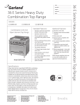
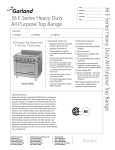
1
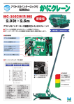
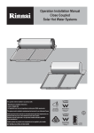
Item
Quantity
Flight Machine
CSI Section 11400
Approval
Date
Models
JFT
Options
Blower dryer
Additional wash section
Additional load module
Additional unload module
25’ (8 m) wash down
hose - mounted
Electrical connection with
circuit breakers
Dual point electrical connection
Low profile doors
Flanged feet
Multiple conveyor peg choice
Drain at load or unload end
Standard Features
• Uses 140 gallons (530 ltrs) of water per hour with sanitizing
hot water rinse
• All tanks and hoods constructed from 16 gauge 304 stainless
steel with a No. 3 finish and heliarced welded
• Stainless steel frame, legs and feet
• Two tank rackless conveyor shall have a maximum capacity
of 17,101 dishes per hour at an NSF rated belt speed of 8.63
feet per minute. At 6.4 feet (2 m) per minute capacity will be
12,726 dishes per hour.
• Belt width of 29” (737 mm) and a maximum clearance of 25”
(635 mm) throughout the machine
• Enclosure panels, hood and doors are stainless steel and double wall insulated to reduce heat dissipation, outside surface
temperatures, and noise pollution
• Insulated access doors for removal, cleaning and servicing
• V-shape tank(s) design to increase visibility and accessibility
for cleaning as well as insure complete tank draining
• Heated power rinse zone uses fresh rinse water a second
time to provide pristine results
• A sequential digital temperature readout of each tank
housed in the door of the electrical control panel. The readouts will constantly display the temperature of the prewash,
wash, power rinse and final rinse in 5 second intervals
• A ball valve in the drain line of each tank and interconnected
to a common machine drain connection at the load end of
the machine
• Each tank will be automatically filled and maintained by a
water level float. Water will be automatically added to the
machine when required
• Block manifold wash arms are easy to remove, clean, and
replace with non-clogging convex wash arm jets
• Large, removable scrap screens
• Self draining stainless steel pumps, impellers, and housings are readily accessible and serviceable
• Conveyor belt drive operates at two speeds and is protected by an overload safety device and an automatic
shut-down actuator
• Each door is equipped with a door safety switch to prevent it from running when the door(s) are open. If a door
is opened during operation the switch will immediately
shut down the machine
• Operator activated start-stop switches on both the load
and unload ends and the control panel
• Removable insulated panels to enclose the unit down
to the base frame on both the front and rear of the
machine
• A single, built-in 18” (457 mm) diameter indirect vent
connection with a 0.19 HP exhaust fan mounted in a
cleanable cross duct on the machine for condensate
removal and indirect vent connection
• 3” minimum wall clearance
• Service access from front of machine
Highway 25E
Tel: 606-523-9795
www.jacksonmsc.com
P. O. Box 1060
Tel: 1-888-800-5672
07610-002-85-11 (8/07)
Barbourville, KY 40906
Fax: 606-523-9196
E-mail: [email protected]
FLIGHT
Project
Load
Pre-wash Tank
Wash Tank
A “start/stop” switch is located at
the load end of the machine for the
operators convenience
The pre-wash tank features a stainless
steel manifold system with stricturefree jets to optimize pressure for soil
removal and to provide easy access for
removal and cleaning.
The wash tank features a stainless
steel manifold system with stricturefree jets to optimize pressure for soil
removal and to provide easy access
for removal and cleaning.
A 3.0 HP, 1725 RPM motor and pump
is horizontally mounted. The pump
housing is stainless steel and selfdraining. A stainless steel strainer
with a removable basket is included.
The pre-wash tank is a sloped design
to ensure complete tank draining and
to minimize soil build-up.
A 3.0 HP 1725 RPM motor and pump
is horizontally mounted. The pump
housing is stainless steel and selfdraining. A stainless steel strainer
pan is included. The wash tank is a
sloped design to ensure complete
tank draining and to minimize soil
build-up.
Load platform is 12 gauge stainless
steel.
Power Rin
Stainless steel pow
stricture free jets m
below the wares ar
for cleaning.
A 2.0 HP, 1725 RP
stainless steel hou
are included. Pow
sloped design to
tank draining and
build-up
Machine Dimensions
Load
Pre-wash Tank
Power Rins
Wash Tank
Height
Depth
Length
Height
Depth
Length
Height
Depth
36”
(914.4 mm)
38-1/4”
(972 mm)
36”
(914.4 mm)
73”
(1854 MM)
46”
(1168 MM)
36”
(914.4 mm)
73”
(1854 mm)
46”
(1168 mm)
Height
Dep
36”
(914.4 mm)
73”
(1854 mm)
46”
(1168 m
Height
Length
Shipping Dimensions
Load / Unload (Shipped Together)
Height
Depth
71”
(914.4 mm)
48”
(1219 mm)
Length
60”
(1524 mm)
Weight: 621 lbs / 282 kg
Pre-wash Tank
Wash Tank
Power Rin
Height
Depth
Length
Height
Depth
Length
79”
(2007 mm)
48”
(1219 mm
60”
(1524 mm)
79”
(2007 mm)
48”
(1219 mm
60”
(1524 mm)
Weight: 642 lbs / 291 kg
Weight: 642 lbs / 291 kg
79”
(2007 mm)
Dep
48
(1219
Weight: 627 l
Final Rinse
Blower Dryer
Unload
Stainless steel rinse arms with jets
mounted above and below the wares
are easily removable for cleaning.
A stainless steel tunnel incorporated into the discharge section of the
machine. The blower dryer keeps the
operating personnel from removing
the wares before it reaches the end of
the unload section. An industrial fantype with a squirrel cage driven by
a 0.6 HP direct drive motor dries the
wares as it exits the machine.
A “start/stop” switch is located at
the unload end of the machine for
the operators convenience.
nse Tank
wer rinse arms with
mounted above and
re easily removable
PM motor with a
using and impeller
wer rinse tank is a
ensure complete
d to minimize soil
The final rinse water will cascade back
to the power rinse, wash and then the
pre-wash tanks.
*The Blower Dryer is an option
and must be specified at time
of order.
se Tank
pth
mm)
Final Rinse
8”
9 mm
The drive wheel shaft is supported
by two heavy-duty grease-lubricated ball bearings in pillow blocks.
Blower Dryer
Unload
Length
Height
Depth
Length
Height
Depth
Length
Height
Depth
36”
(914.4 mm)
82”
(2083 mm)
46”
(1168mm)
36”
(914.4 mm)
88“
(2235 mm)
38-1/4”
(972 mm)
36
(914.4 mm)
36”
(914.4 mm)
38-1/4”
(972 mm)
nse Tank
pth
Unload platform is 14 gauge stainless steel.
Final Rinse
Blower Dryer
Height
Depth
Length
Height
Depth
Length
60”
(1524 mm)
88”
(2235 mm)
48”
(1219 mm
60”
(1524 mm)
93”
(2362 mm)
48”
(1219 mm
60”
(1524 mm)
Weight: 635 lbs / 288 kg
42”
(1067 mm)
Unload / Load
Length
lbs / 284 kg
Length
Weight: 504 lbs / 229 kg
Shipped with load end
1'-23
4" [375mm]
3" [76mm] Minimum
Floor Sink or Floor Drain
(Optional to drain at load or
unload end of the machine.)
5
2
3" [76mm] Minimum
Floor Sink or Floor Drain
(Optional to drain at load or
unload end of the machine.)
1
4
3
3' [914mm]
3' [914mm]
3' [914mm]
3' [914mm]
3' [915mm]
1" [1943mm]
6'-42
Control Cabinet Door Open
1" [972mm]
3'-24
2'-33
4" [706mm]
6
3' [914mm]
7
12'-7" [3836mm]
2'-53
8" [746mm]
2'-43
8" [721mm]
1" [234mm]
94
1" [743mm]
2'-54
1" [1048mm]
3'-54
1" [971mm]
3'-24
3'-10" [1168mm]
1" [486mm]
1'-78
1" [4712mm]
15'-52
13'-6" [4115mm]
9" [229mm]
1" [486mm]
1'-78
Electric
3'-6" [1067mm]
18'-6" [5639mm]
DIRECTION OF OPERATION
5
7
1
3' [914mm]
6
13'-6" [4115mm]
1" [4712mm]
15'-52
3" [72mm] Deep
18" [457mm] I.D. Square
Condensate Exhaust Duct
Minimum 18" Square (Cross Section 324 Sq. In.)
Provided by HVAC Contractor
Exhaust Requirements
- 1200 CFM
Condensate duct to extended into duct pan.
6'-10" [2083mm]
A.F.F.
Condensate duct pan mounted on top of
dishmachine electrical section.
103
4" [273mm]
12'-7" [3836mm]
6" [152mm]
1" [129mm]
58
TYPICAL
Legend
1 - 1-1/2" NPT Machine Drain Connection
(Floor drain - optional to either end)
2 - *Wash Tank Electrical Connection
3 - *Rinse Tank Electrical Connection
4 - *Booster Heater Electrical Connection
5 - *Motor Controls Electrical Connection
6 - 3/4" NPT Incoming Water Connection
7 - Condensate Connection - See Detail
*See Table For Amp Draw
Note:
The condensate removal system built into the dishmachine consists of a fan
that will remove 1200 CFM. A single condensate connection must be provided
by the installing contractor. This is an indirect connection that must be capable
of removing 1200 CFM from the area.
Visit us at www.jacksonmsc.com or call us at 1-888-800-5672
6'-10" [2083mm]
Top of Exhaust Fan Housing
4
5'-43
4" [1644mm]
3
6" [152mm]
87
8" [226mm]
3' [914mm]
6'-1" [1855mm]
7'-6" [2286mm]
Optional - Short Doors In The Open Position
9'-2" [2794mm]
Doors In The Open Postion
2
9'-6" [2896mm]
Maximum Ceiling Height for Short Doors - 7'-10" [2388mm]
Power Connections Inside Control Panel
1" [4712mm]
15'-52
1" [743mm]
2'-54
1" [234mm]
94
3" [72mm] Minimum
Floor Sink or Floor Drain
(Optional to drain at load
or unload end of the machine.)
5
3" [72mm] Minimum
Floor Sink or Floor Drain
(Optional to drain at load or unload
end of the machine.)
2
1
4
1" [1048mm]
3'-54
2'-53
8" [746mm]
2'-43
8" [721mm]
3'-10" [1168mm]
7
1" [971mm]
3'-24
1" [486mm]
1'-78
9" [229mm]
12'-7" [3836mm]
6
1'-23
4" [375mm]
2'-33
4" [706mm]
3' [914mm]
1" [972mm]
3'-24
3
3'-6" [1067mm]
3' [915mm]
3' [914mm]
3' [914mm]
3' [914mm]
3' [914mm]
18'-6" [5639mm]
DIRECTION OF OPERATION
6" [152mm]
1" [129mm]
58
Typical
1
12'-7" [3836mm]
13'-6" [4115mm]
6
1" [4711mm]
15'-52
Jackson Rackless Conveyors
Jackson Rackless Conveyors
Wash, Power Rinse & Final Rinse (18’-6” minimum length)
Wash, Power Rinse & Final Rinse (18’-6” minimum length)
Electric equirements with booster
Electric requirements with booster and blower dryer
Wash
Rinse
KW
208V
230V
460V
KW
208V
230V
460V
24
76.3
69.9
35.0
Wash
24
76.3
69.9
36.0
35.4
Rinse
26
77.8
70.8
35.4
26
Motors and Controls
Booster
Total
27
77.8
70.8
12.2
12.3
6.2
Blower Dryer, Motors and Controls
20
43.7
41.4
20.7
75.0
67.8
33.9
Booster
27
75.0
67.8
33.9
110.5
Total
272.8
249.9
126
241.3
220.8
Visit us at www.jacksonmsc.com or call us at 1-888-800-5672
9'-2" [2794mm]
Doors In The Open Position
7'-6" [2286mm]
Optional - Short Doors In The Open Position
3' [914mm]
2
3' [914mm]
103
4" [273mm]
5'-43
4" [1644mm]
6'-10" [2083mm]
Top of Exhaust Fan Housing
3
7
6'-1" [1855mm]
4
5
9'-6" [2896mm]
Maximum Ceiling Height for Short Doors - 7'-10" [2388mm]
Power Connections Inside Control Panel
6" [152mm]
87
8" [226mm]
1" [1943mm]
6'-42
Control Cabinet Door Open
1" [486mm]
1'-78
13'-6" [4115mm]
Steam
1" [4712mm]
15'-52
14'-6" [4420mm]
13'-6" [4115mm]
7
1" [3840mm]
12'-74
1" [486mm]
1'-78
3' [914mm]
6
3' [915mm]
3' [913mm]
2
3' [914mm]
3' [914mm]
1" [1945mm]
6'-42
Control Cabinet Door Open
3"[76mm] Minimum
Floor Sink or Floor Drain
(Optional to drain at load or
unload end of the machine.)
1'-23
4" [375mm]
4
5
1" [972mm]
3'-24
1
3'-05
8" [930mm]
2'-33
4" [705mm]
1" [724mm]
2'-42
1" [486mm]
1'-78
9" [229mm]
3
7'-8" [2335mm]
2'-53
8" [745mm]
2'-43
8" [719mm]
3' [914mm]
1" [972mm]
3'-24
1" [1048mm]
3'-54
3'-10" [1168mm]
3" [72mm] Minimum
Floor Sink or Floor Drain
(Optional to drain at load
or unload end of the
machine.)
10" [254mm]
8
10'-8" [3250mm]
3'-6" [1067mm]
18'-6" [5639mm]
CONTROL
CABINET
3' [915mm]
3
1" [343mm]
1'-12
4
103
4" [273mm]
10'-8" [3250mm]
1
85
8" [219mm]
5
6" [152mm]
6
6'-10" [2084mm]
Top of Condensate Duct Pan
POWER RINSE
SECTION
5'-43
4" [1644mm]
WASH
SECTION
87
8" [226mm]
6" [152mm]
10" [253mm]
6'-1" [1855mm]
7'-6" [2286mm]
Optional - Short Doors In The Open Position
PREWASH
SECTION
8
7'-8" [2335mm]
1" [3843mm]
12'-74
7
13'-6" [4115mm]
14'-6" [4420mm]
1" [4712mm]
15'-52
Legend
3" [72mm] Deep
18" [457mm] I.D. Square
Condensate Exhaust Duct
Minimum 18" Square (Cross Section 324 Sq. In.)
Provided by HVAC Contractor
Exhaust Requirements
- 1200 CFM
Condensate duct to extended into duct pan.
Condensate duct pan mounted on top of
dishmachine electrical section.
6'-10" [2083mm]
A.F.F.
9'-2" [2794mm]
Doors In The Open Position
2
1 - 1-1/2" NPT Machine Drain Connection
(Floor drain - optional to either end)
2 - Electrical Connection - See Table for Amp Draw
3 - 3/4" NPT Incoming Water Connection
4 - 1-1/2" NPT Steam Connection
5 - 3/4" NPT Wash Section Condensate Return
6 - 3/4" NPT Power Rinse Section Condensate Return
7 - 3/4" NPT Booster Heater Condensate Return
8 - Condensate Connection - See Detail
Note:
The condensate removal system built into the dishmachine consists of a fan
that will remove 1200 CFM. A single condensate connection must be provided
by the installing contractor. This is an indirect connection that must be capable
of removing 1200 CFM from the area.
Visit us at www.jacksonmsc.com or call us at 1-888-800-5672
9'-6" [2896mm]
Maximum Ceiling Height for Short Doors - 7'-10" [2388mm]
DIRECTION OF OPERATION
1" [4712mm]
15'-52
14'-6" [4420mm]
13'-6" [4115mm]
7
1" [3840mm]
12'-74
3' [914mm]
3'-10" [1168mm]
2'-43
8" [719mm]
1" [1048mm]
3'-54
7'-8" [2335mm]
2'-53
8" [745mm]
1" [743mm]
2'-54
1" [972mm]
3'-24
1" [486mm]
1'-78
9" [229mm]
10" [254mm]
1" [486mm]
1'-78
10'-8" [3250mm]
3
2'-33
4" [705mm]
3'-05
8" [930mm]
1" [972mm]
3'-24
1" [1944mm]
6'-42
Control Cabinet Door Open
1" [724mm]
2'-42
8
1'-23
4" [375mm]
1
1" [240mm]
92
4
3" [72mm] Minimum
Floor Sink or Floor Drain
(Optional to drain at load or
unload end of the machine.)
2
3'-6" [1067mm]
3' [914mm]
3" [72mm] Minimum
Floor Sink or Floor Drain
(Optional to drain at load or
unload end of the machine.)
5
6
3' [914mm]
3' [915mm]
18'-57
8" [5637mm]
3' [913mm]
3' [914mm]
8
6" [152mm]
85
8" [219mm]
103
4" [273mm]
1" [343mm]
1'-12
4
6
5
7'-8" [2335mm]
1
10'-8" [3250mm]
7
1" [3843mm]
12'-74
13'-6" [4115mm]
14'-6" [4420mm]
1" [4712mm]
15'-52
Jackson Rackless Conveyors
Jackson Rackless Conveyors
Wash, Power Rinse & Final Rinse (18’-6” minimum length)
Wash, Power Rinse & Final Rinse (18’-6” minimum length)
Steam tank heat electrical requirements with booster
Steam tank heat, booster and blower dryer electrical requirements
Wash
208V
230V
460V
9.7
9.7
4.9
Wash
208V
230V
460V
9.7
9.7
4.9
2.8
Rinse
5.6
5.6
2.8
Rinse
5.6
5.6
Pre-wash/Drive/Exhaust
12.2
12.3
6.2
Pre-wash/Drive/Exhaust
18.7
17.9
6.2
Total
27.5
27.6
13.9
Total
34.0
33.2
13.9
Visit us at www.jacksonmsc.com or call us at 1-888-800-5672
9'-6" [2896mm]
9'-2" [2794mm]
Door In The Open Position
7'-6" [2286mm]
Optional - Short Doors In The Open Position
87
8" [226mm]
3' [915mm]
3
10" [253mm]
PREWASH
SECTION
WASH
SECTION
6" [152mm]
POWER RINSE
SECTION
6'-1" [1855mm]
CONTROL
CABINET
5'-43
4" [1644mm]
6'-10" [2084mm]
Top Of Condensate Duct Pan
2
Maximum Ceiling Height for Short Doors - 7'-10" [2388mm]
DIRECTION OF OPERATION
Flight Machine
ELECTRICAL
An electromechanical control system for increased reliability mounted in a stainless steel control cabinet on the front of the machine.
A step-down transformer is included to provide 115 volt, 60 cycles, 1 phase operation for controls including selenoid valves, timers,
etc. Wiring is 105 C, 600-volt thermoplastic insulated wire and routed throught UL approved conduit.
Low watt density tubular heating elements are mounted inside the wash and power rinse tanks and are easily removable from the
exterior of the unit. Heaters are protected by a water level float switch control and a high limit overload.
Tank water temperature is maintained by a fast reacting thermostat which will control the heating element.
STEAM
Stainless steel tubular steam coils mounted inside the wash and power rinse tanks below the optimum water level and protected by
a water level float switch control. An external “Y” strainer and high temperature steam solenoid to regulate the flow of steam through
the coil. Tank temperature is controlled and maintained by a fast reacting thermostat that will control the operation of the steam
solenoid. A float and thermostatic steam trap to remove the condensate from the coil are included. Steam coils will require a 15-30
PSI flowing steam pressure.
BOOSTER HEATERS - ELECTRIC
An internally mounted 27 kW electric booster heater sized to raise incoming 110˚F (43˚C) water supply to 180˚F (82˚C) minimum
for sanitizing rinse. The electric booster heater will have the capacity to heat 155 GPH from 110˚F (43˚C) to 180˚F (82˚C) minimum.
The tank is designed for a working pressure 150 PSI and hydrostatically tested at 300 PSI. The heater is complete with all plumbing,
including NPT pipe and fittings from inlet and outlet. Electric heating elements are metal sheathed controlled by a close tolerance
immersion thermostat. The booster is protected with a high temperature limit switch and low water cut-off.
BOOSTER HEATERS - STEAM
An internally mounted steam booster heater sized to raise incoming 110˚F (43˚C) water supply to 180˚F (82˚C) minimum for sanitizing rinse. The steam booster heater will have the capacity to heat 216 GPH from 110˚F (43˚C) to 180˚F (82˚C) minimum. The tank is
designed for a working pressure 150 PSI and hydrostatically tested at 300 PSI. The heater is complete with all plumbing, including
NPT pipe and fittings necessary to meet all installation requirements. The booster is protected with a high temperature limit switch
and low water cut-off.
DIMENSION REQUIREMENTS
STEAM REQUIREMENTS
Wall Clearance (Minimum)
3” / (19 mm)
25”H x 30”W
(635 mm x 762 mm)
Inside Clearance
OPERATING CAPACITY
Dishes per Hour - Belt Speed 6.4 FPM
12,726
Dishes per Hour - Belt Speed 8.6 FPM
17,101
OPERATING TEMPERATURES
Steam Flow Pressure (PSIG)
15-30
Consumption @ 110˚F Incoming Water Temperature
145 lbs./hr.
Consumption with blower dryer
245 lbs.hr.
WATER REQUIREMENTS
Inlet Tempterature
110˚F / (43˚C)
Gallons per Hour
140 / (530 Ltr)
Waterline Size IPS (Minimum-inches)
3/4 / (19 mm)
Drainline Size IPS (Minimum-Inches)
2 / (51 mm)
Pre-Wash (Recommended)
140˚F / (60˚C)
Wash (Minimum)
152˚F / (67˚C)
Rinse (Minimum)
161˚F / (72˚C)
TANK CAPACITY
Final Rinse
180˚F / (82˚C)
Pre-wash Tank
36 gal / (136 ltr)
Wash Tank
36 gal / (136 ltr)
Power Rinse Tank
36 gal / (136 ltr)
MOTORS
Flow Pressure (PSI)
15-25
Pre-wash Pump Motor
3.0 HP
Wash Pump Motor
3.0 HP
PUMP CAPACITY
Power Rinse Pump Motor
2.0 HP
Pre-wash Pump
260 gal / (984 ltr)
Conveyor Drive Motor
1/4 HP
Wash Pump
260 gal / (984 ltr)
Power Rinse Pump
230 gal / (871 ltr)
HOW TO SPECIFY - JFT:
Highway 25E
Tel: 606-523-9795
www.jacksonmsc.com
P. O. Box 1060
Tel: 1-888-800-5672
07610-002-85-11 (8/07)
Barbourville, KY 40906
Fax: 606-523-9196
E-mail: [email protected]
We reserve the right to change specifications appearing in this bulletin without incurring any obligation for equipment previously or subsequently sold.