1
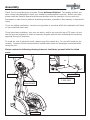
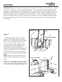
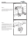
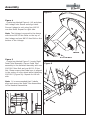
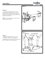
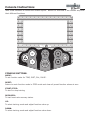
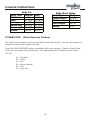
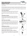
Owner’s Manual
Achiever Elliptical
Customer Service
1.800.750.IRON
1.800.750.4766
4009 Distribution Drive
Suite 250
Garland, TX 75041
www.ironmanfitness.com
315-00084
10/06 Rev B
CAUTION! Read all precautions
and instructions in this manual
before using this equipment.
Table of Contents
Important Safety Information
3-4
Assembly
5-10
Console Instructions
11-16
Monitoring Your Heart Rate
17
Warm-Up Exercises
18
Troubleshooting/Cleaning/Maintenance
19
Parts List
20
Exploded Views
21
Warranty Information
22
Important Safety Information
WARNING! Before using this unit or starting any exercise program, consult your physician.
This is especially important for persons over the age of 35 and/or persons with pre-existing
health problems. The manufacturer or distributor assumes no responsibility for personal injury
or property damage sustained by or through the use of this product.
WARNING! To reduce the risk of electrical shock, burns, fire, or other possible injuries to the
user, it is important to review this manual and the following precautions before operation.
SAFETY PRECAUTIONS AND TIPS
1. It is the owner's responsibility to ensure that all users of this unit have read the Owner's
Manual and are familiar with warnings and safety precautions.
2. This unit has a user maximum capacity of 300 pounds.
3. The unit should only be used on a level surface and is intended for indoor use only. The unit
should not be placed in a garage, patio, or near water and should never be used while you are
wet. Ironman Fitness recommends a mat be placed under the unit to protect floor or carpet
and for easier cleaning.
4. Follow safety information in regards to plugging in your unit. Do not run the power cord
underneath your unit. Do not operate the unit with a damaged or frayed power cord.
5. Wear comfortable, good-quality walking or running shoes and appropriate clothing. Do not
use the unit with bare feet, sandals, socks or stockings.
6. Always examine your unit before using to ensure all parts are in working order.
7. Allow the unit to fully stop before dismounting.
8. Pets should never be allowed near the unit.
9. Do not leave children unsupervised near or on the unit.
10. Never operate the unit where oxygen is being administered, or where aerosol products are
being used.
11. Never insert any object or body parts into any opening.
12. For safety and to prevent damage to your unit, no more than one person should use the
unit at a time.
13. Always unplug the unit before cleaning and/or servicing. Service to your unit should only be
performed by an authorized service representative, unless authorized and/or instructed by the
manufacturer.
14. Failure to follow these instructions will void the unit warranty.
Important Safety Information
SAFETY PRECAUTIONS AND TIPS FOR CHEST STRAP
1. It is the owner's responsibility to ensure that all users of this unit have read the Owner's
Manual and are familiar with warnings and safety precautions.
2. Do not place chest strap near devices that generate large magnetic fields. TV sets, electric
motors, radios, and high voltage power lines can affect the transmitter’s performance. These
items can interfere with the heart rate signal and possibly affect the heart rate readings on the
console.
3. Handle the Chest Strap with care. Dropping the transmitter might cause damage that could
void the warranty.
4. Do not use the chest strap if you have a cardiac pacemaker or if your are taking medications
for a heart condition. Medication or electrical pulses from the pacemaker can interfere with
accurate heart rate readings.
5. Do not bend the strips inside the chest strap. This can cause the chest strap to lose
conductivity.
6. The chest strap has batteries that need to be replaced periodically. A faulty battery can
cause inaccurate reading.
7. It is suggested for the Chest Strap Transmitter that you position the transmitter as close
to your heart as possible, against the skin, 1-2 inches below the pectoral muscles. For best
results, moisten the back of the transmitter for better contact.
Assembly
Thank You for purchasing the Ironman Fitness Achiever Elliptical! The quality product you
have chosen was designed to meet your needs for cardiovascular exercise. Before you start,
please read the Owner’s Manual and become familiar with the operation of your new unit.
Remember to take time to perform stretching exercises, provided in this manual, to help avoid
injury.
If you are taking medication, consult your physician to see what affect the medication will have
on your exercise heart rate.
If you have heart problems, your are not active, and/or are over the age of 35 years, do not
use the pre-set programs or start an exercise program without first contacting and receiving
approval from your physician.
To avoid the risk of electrical shock, always keep the console dry. Do not spill liquids on the
console. Ironman Fitness recommends a sealed water bottle for beverages consumed while
using the unit.
Please review the following drawing below to familiarize yourself with the listed
parts.
HANDLEBARS
AC ADAPTER
CONSOLE
LEVELER FEET
2 PER SIDE
PULSE GRIP
HANDLEBARS
PEDALS
Assembly
Getting Started - The Ironman Fitness Achiever Elliptical will require some assembly. Unpack
the box in a clear area. Remove packing material. Do not dispose of packing material until
assembly is complete and unit is working properly. Place the unit on a clean level surface for
assembly. Make sure there is easy access to an electrical outlet. Before assembling, the unit
should be placed as close as possible to its final location. Locate all hardware bags, labeled
Figure 1 through Figure 9, with the exception of Figure 8. If you are missing any bags, please
call Ironman Fitness at 1-800-750-4766. Tools have been provided for use while assembling
this product.
Figure 1
CONSOLE TUBE
Figure 1
Locate bag labeled Figure 1. Locate
Console Tube. Attach Console Tube to
Main Frame. Slide Tube down into Main
Frame. Connect Upper Console Wire
to Lead Wire Assembly. Secure using
three M10*80 mm Hex Head Screws
extending through the frame and
Console Tube, three 10x20 Washers and
three Crown Nuts, M10*1.5. Use three
M10*120 Hex Screw to secure through
the Front of the Console Tube and Main
Frame.
Note: Ensure that all wires are secure
inside console. Be careful not to pinch
wires.
UPPER CONSOLE WIRE
LEAD WIRE ASSEMBLY
CROWN NUT, M10*1.5
M10*80 HEX SCREW
Note: Do not tighten Screws until
you have fully completed Figure 2.
M10*120 HEX SCREW
Assembly
Figure 2
CONSOLE TUBE
COVER
Figure 2
Locate Bag labeled Figure 2. Locate Cover.
Secure Cover to Main Frame by using three
M5*8 Screws through the left side of unit.
Repeat for the right side.
M5*8 SCREW
Figure 3
CONSOLE TUBE
Figure 3
Locate Bag labeled Figure 3. Locate Left
and Right Handrail Assemblies. Secure
Left Handrail Assembly to Console tube by
using one Washer, one Spring Washer, one
M10*20 Hex Bolt, and one End Cap. Repeat
for the right side.
Note: The Handrail Assembly will only
go onto the Console Tube one way. The
connector on the middle of the Handrail
Assembly will face outwards.
SPRING WASHER
M10*20, HEX BOLT
WASHER
END CAP
HANDRAIL ASSEMBLY
Assembly
Figure 4
Figure 4
Locate bag labeled Figure 4. Lift and place
left Linkage onto Sleeve and align holes.
Secure Linkage to unit using four M8*12
mm Hex Bolts. Repeat for right side.
Note: The Linkage is secured to the sleeve
with three M8*12 Hex Bolts on the top of
the Linkage and one M8*12 Hex Bolt on the
bottom of the Linkage.
SLEEVE
LINKAGE
M8*12 HEX BOLT
Figure 5
Locate bag labeled Figure 5. Locate Right
Pedal Tube Assembly. Secure Pedal Tube
assembly to the Handrail Assembly with one
M10*81.5 Hex Bolt and one M10*1.5 Hex
Nut. Please ensure that Pedal arm is aligned
in the center of roller wheel while tightening
M10*81.5 (Figure 5a). Repeat for the left
side.
Figure 5
HANDRAIL ASSEMBLY
PEDAL TUBE ASSEMBLY
Note: It is recommended that 2 adults
align and secure the Pedal Tube Assemblies
to the Handrail Assemblies.
Figure 5a
M10*1.5 HEX NUT
M10*81.5 HEX BOLT
Assembly
Figure 6
Figure 6
Locate bag labeled Figure 6. Locate
Bracket Covers. Attach bracket Cover to
the Handrail Assembly by lining up hole,
and securing using one Screw, M5X0.8-12.
Repeat for other side.
HANDRAIL ASSEMBLY
SCREW
Note: Do not overtighten screw, this will
damage Bracket Cover.
BRACKET COVER
Figure 7
LEFT HANDLEBAR
RIGHT HANDLEBAR
CONSOLE TUBE
Figure 7
Locate bag labeled Figure 7. Locate
Handlebars. Attach Left Handlbar to
Handlebar Assy using three M8*16mm Hex
Bolts. Repeat for other handlebar.
M8*16 HEX BOLT
Assembly
Figure 8
Figure 8
Locate Console. Carefully feed Pulse Wires
from the Console down the Console tube.
Connect Upper Console Wire to the appropriate location on the back of the Console.
Secure Console to Console Tube using four
Screws.
Note: The four Console Screws will already
be installed into the back of Console when
you remove it from the box.
Figure 9
Figure 9
Locate bag labeled Figure 9. Connect
the Pulse Wires coming from the Pulse
Handlebar Assy to the Pulse Wires from the
Console. Secure Pulse Handlebar Assembly
to Console Tube using six M6*10 Hex
Socket Head Bolts.
Note: Ensure that all wires are secure
inside console tube. Be careful not to pinch
wires.
PULSE WIRE
PULSE HANDLEBAR ASSY
M6*10 HEX SOCKET BOLT
CONGRATULATIONS!
You have completed assembly of your Achiever Elliptical.
10
Console Instructions
Take a few moments to review the console layout. Below is a overview of the console keys and
their different functions.
C OVER Y
RE
BO
DY FAT
UP
MOD
E
FAN
314-00053
R E S ET
ART / STOP
ST
DO WN
ironm
anfitn
om
ess.c
CONSOLE BUTTONS:
MODE:
To set function value for TIME, DIST, CAL, PULSE.
RESET:
Return to main function mode in STOP mode and clean all preset function values at zero.
START/STOP:
To start or stop training
RECOVERY:
To test heart rate recovery status.
UP:
To select training mode and adjust function value up.
DOWN:
To select training mode and adjust function value down.
11
Console Instructions
FAN:
Console is equipped with a fan that has four settings, AUTO/LOW/MED/HIGH/OFF. Press the
button to turn the fan to the preferred setting. The AUTO setting will adjust the fan speed
based on the RPMs produced, the more RPMs produced the faster the fan speed will be.
BODY FAT:
Press the button to start body fat measurement.
CONSOLE FUNCTIONS
TIME:
Count up - No preset target, Time will count up from 00:00 to maximum 99:59 with each
increment is 1 second. Count down - If training with preset time, time will count down from
preset to 00:00. Each preset increment or decrement is 1 minute between 1:00 to 99:00.
SPEED:
Display current training speed from 0.0 to maximum 99.9 km or ml.
RPM:
Display current training revolutions per minute.
DISTANCE:
Count up - No preset target, Distance will count up from 0.00 to maximum 99.90 with each
Increment 0.1 MPH/KM. Count down - If training with preset target, Distance will count down
from preset to 0.00. Each preset increment or decrement is 0.1 KM (or ML) between 0.00 to
99.90.
CALORIES:
Count up - No preset target, Calories will count up from 0 to maximum 990 with each 1 cal
increment. Count down - If training with preset target, Calories will count down from preset
calories to 0. Each preset increment or decrement is 10 cal from 0 to 990 cal.
PULSE:
Displays your current heart beat figures as soon as both hands are holding the pulse sensor.
The monitor will detect your heart rate through hand grip sensors or chest strap (make sure
that the plug in receiver has been attached to the console), with the chest strap giving the
most accurate reading.
WATT:
Display current training watt figures.
RECOVERY:
After exercising for a period of time, keep holding on handgrips and press “RECOVERY” button. All function display will stop except “TIME” starts counting down from 00:60 to 00:00.
Screen will display your heart rate recovery status with the F1, F2 to F6. F1 is the best, F6
is the worst. User may keep exercising to improve the heart rate recovery status. (Press the
RECOVERY button again to return the main display.)
12
Console Instructions
CALENDAR:
Screen will display year/month/day in sleep mode. When the unit is plugged in, the console will
prompt user to input correct information. Use the UP and DOWN button until correct year is
found. Press Mode to select and move on to the Month. Repeat to input correct month and day.
Note: All information will be saved until unit is unplugged.
CLOCK:
Screen will display time in sleep mode. Once the calendar is set, you will be able to input the
correct time. Use the UP and DOWN buttons until the correct hour found. Press Mode to select
and move on to the minutes. Repeat for to input correct minutes. Note: All information will be
saved until unit is unplugged.
TEMPERATURE:
Screen will display room temperature in sleep mode.
GENERAL INFORMATION:
1. Start Pedaling or press any button to start Console.
2. The Console will shut down after 4 minutes of no activity, and will display room temperature.
3. To Reset Console press and hold the START/STOP button for 2 seconds.
Note: The values calculated or measured by the console are for exercise purposes only, not for
medical purposes.
BMR:
Basal Metabolic Rate (metabolism) is the energy (measured in calories) expended by the body
at rest to maintain normal body functions.
BMI:
Stands for Body Mass Index. BMI is a measure which takes into account a person’s weight and
height to gauge total body fat in adults.
GETTING STARTED:
Press the USER button. Press MODE to enter USER SELECT. Use the UP/DOWN to select a
User. Press ENTER to select a User. Press the UP/DOWN key to select HEIGHT. Press ENTER
to confirm the value. Use the UP/DOWN key to select WEIGHT. Press MODE to confirm value.
Use the UP/DOWN key to select AGE. Press ENTER to confirm value. Use the UP/DOWN key to
select GENDER. Press MODE to confirm value. Press START/STOP to enter program mode.
PROGRAM INSTRUCTIONS:
MANUAL PROGRAM:
Allows the User to manually adjust tension settings throughout their workout. The default tension level is 1. You may set Time or Distance for your workout.
13
Console Instructions
Use the UP/DOWN buttons to scroll to this program. Press MODE to select this program. TIME
will flash in the display. Use the UP/DOWN keys to set desired TIME. Press MODE to confirm
value. Repeat steps for DISTANCE and KCAL. Press START/STOP to begin exercising. Grasp
Pulse Grips loosely with both hands to activate PULSE function. You can change the tension
level at any time during your workout session by pressing the UP/DOWN buttons.
PRESET PROGRAMS:
Each Program is divided into ten intervals.
Use the UP/DOWN buttons to scroll to this program. Press MODE to select this program. TIME
will flash in the display. Use the UP/DOWN keys to set desired TIME. Press MODE to confirm
value. Repeat steps for DISTANCE and KCAL. Press START/STOP to begin exercising. Grasp
Pulse Grips loosely with both hands to activate PULSE function.
USER PROGRAM:
It allows you to customize a workout session. This program is divided into 10 intervals. TIME,
DISTANCE, KCAL and Tension can be set for each interval. The program will be stored in the
Console’s memory after set-up.
Use the UP/DOWN buttons to scroll to this program. Press MODE to select this program. TIME
will flash in the display. Use the UP/DOWN keys to set desired TIME. Press MODE to confirm
value. Repeat steps for DISTANCE and KCAL. Column 1 will flash on display. Use the UP/
DOWN keys to set Tension for this interval. Press MODE to confirm value. Repeat for Interval
2-10. Press START/STOP to begin exercising. Grasp Pulse Grips loosely with both hands to
activate PULSE function. You can change the tension level at any time during your workout
session by pressing the UP/DOWN buttons. If the tension level is changed during your exercise
session, this new value will not be saved into the console.
To make a permanent change, you must call up program again and repeat steps for each interval with new tension settings.
WATT PROGRAM:
In the program, the WATT function will keep a constant value. This means that if you pedal
quickly, the tension will decrease, if you pedal slowly the tension will increase to maintain the
Watt value entered.
WATT = TORQUE (KGM) * RPM *1.03. For this program you must choose to set a TIME or a
DISTANCE. Use the UP/DOWN buttons to scroll to this program. Press MODE to select this
program. TIME will flash in the display. Use the UP/DOWN keys to set desired TIME. Press
ENTER to confirm value. Repeat steps for DISTANCE, KCAL and WATT. Press START/STOP to
begin exercising. Grasp Pulse Grips loosely with both hands to activate PULSE function.
HEART RATE PROGRAMS:
Heart rate control programs are designed to automatically adjust the elliptical's resistance to
keep your heart rate at a predetermined level based on the selected Heart Rate program. Each
Heart Rate program is designed with a specific goal.
14
Console Instructions
In all Heart Rate Control programs, the console only accepts the heart rate signal from the
chest strap transmitter. Make sure that the Heart Rate Receiver is plugged into the side of the
Console. The chest strap will not function if it is not plugged in. Once the Heart Rate Receiver
is plugged in, the pulse grip heart rate function is disabled. The requirement to wear the chest
strap is due to the superior accuracy of a chest strap transmitter compared to the pulse grip
sensors.
Proper Installation of Heart Rate Receiver
It is suggested on the Chest Strap Transmitter positioning that you place the transmitter as
close to your heart as possible, against the skin about 1-2 inches below the pectoral muscles.
For best results, moisten the back of the transmitter for better contact.
There are three Heart Rate Programs. 60% HRC (Heart Rate Control), 75% HRC and 85%
HRC. The Console will adjust the Tension to keep you within your Target Heart Rate ± 5.
Example: The tension will increase if your Heart Rate is below the Target Heart Rate. The
tension will decrease if your Heart Rate is higher that your Target Heart Rate.
Press MODE until Program number shows on display. Use the UP/DOWN buttons to scroll to
this program. Press MODE and set values for TIME, DISTANCE, KCAL, AGE and TARGET HEART
RATE. Use the UP/DOWN keys to adjust the values. Press MODE after correct value shows on
display. Press START/STOP to begin exercising. Grasp Pulse Grips loosely with both hands to
activate PULSE function. You may also choose the TARGET HEART RATE WORKING PROGRAM
under the 3 main HEART RATE PROGRAMS. This allows the user to set a TARGET HEART RATE
to exercise at for a period of TIME or a set DISTANCE.
BODY FAT PROGRAM:
This program is designed to calculate body fat ratio and to design a specific tension profile. In
order to use this program correctly, make sure the personal data has been input and correct.
Press the BODY FAT button, and hold on to the hand grips to start body fat testing. The console
will display "- - - - - - - - " while testing is in progress. After 8 seconds, you will see the BODY
FAT in percentage and BMI. If the console has experienced an error, it will display one of the
following error codes:
"E-1" - When the console displays this error, it means you did not put your hands
properly on the sensor. Please try again.
"E-4" - When the console displays this error, it means that the BODY FAT is out of range.
After BODY FAT testing is completed, press the BODYFAT button to continue workout.
Note: For a more accurate reading, hold the handgrip with both hands. This is
especially important in Heart Rate Mode or when performing Body Fat or Fitness Test.
15
Console Instructions
Body Fat
Body Type
Female
Athlete
<17%
Lean
17-22%
22-25%
Average
Above Avg 25-29%
Overweight 29-35%
Obese
35+%
Body Mass
Body Type
Underweight
Ideal
Overweight
Obese
Male
<10%
10-15%
15-18%
18-20%
20-25%
25+%
Index
Range
<18.5
18.5-25
25-30
>30
FITNESS TEST: (Pulse Recovery Feature)
The fitness test compares your pulse rate before and after training. You will notice that your
fitness will improve with regular exercise.
Press the PULSE RECOVERY button immediately after your workout. Grasp the Pulse Grips.
Timer will count down from 60 seconds. Your personal fitness will display on the screen.
(F1-F6)
F1
F2
F3
F4
F5
F6
=
=
=
=
=
=
Excellent
Good
Fair
Below Average
Poor
Very Poor
16
Monitoring Your Heart Rate
Monitoring Your Heart Rate
To obtain the greatest cardiovascular benefits from your exercise workout, it is important to
work within your target heart rate zone. The American Heart Association (AHA) defines this target as 60%-75% percent of your maximum heart rate.
Your maximum heart rate may be roughly calculated by subtracting your age from 220. Your
maximum heart rate and aerobic capacity naturally decreases as you age. This may vary from
one person to another, but use this number to find your approximate effective target zone. For
example, the maximum heart rate for an average 40 year-old is 180 bpm. The target heart
rate zone is 60%-75% of 180 or 108-135 bpm. See Fitness Safety below.
Before beginning your workout, check your normal resting heart rate. Place your fingers lightly
against your neck, or against your wrist over the main artery. After finding your pulse, count
the number of beats in 10 seconds. Multiply the number of beats by six to determine your
pulse rate per minute. We recommend taking your heart rate at these times; at rest, after
warming up, during your workout and two minutes into your cool down, to accurately track
your progress as it relates to better fitness.
During your first several months of exercising, the AHA recommends aiming for the lower part
of the target heart rate zone-60%, then gradually progressing up to 75%.
According to the AHA, exercising above 75% of your maximum heart rate may be too strenuous unless you are in top physical condition. Exercising below 60% of your maximum will result
in minimal cardiovascular conditioning.
Check your pulse recovery rate – If your pulse is over 100 bpm five minutes after you stop
exercising, or if it’s higher than normal the morning after exercising, your exertion may have
been too strenuous for your current fitness level. Rest and reduce the intensity next time.
Fitness Safety The Heart Rate chart indicates average rate zones for different ages. A variety
of different factors (including medication, emotional state, temperature and other conditions)
can affect the target heart rate zone that is best for you. Your physician or health care professional can help you determine the exercise intensity that is appropriate for your age and condition.
(MHR) = Maximum Heart Rate
(THR) = Target Heart Rate
220 - age = maximum heart rate (MHZ)
MHZ x .60 = 60% of your maximum heart rate.
MHZ x .75 = 75% of your maximum heart rate.
For example, if you are 30 years old, your calculations will be as
follows:
220 - 30 = 190
190 x .60 = 114 (low end or 60% of MHZ)
190 x .75 = 142 (high end or 75% of MHZ)
30 year-old (THR) Target Heart Rate would be 114-142
17
Warm Up Exercises
EXERCISE GUIDELINES
WARNING! Before beginning this or any exercise program, you should consult your physician.
This is especially important for individuals over the age of 35 or individuals with pre-existing
health problems.
Warming up prepares the body for the exercise by increasing circulation, supplying more oxygen to the muscles and raising body temperature. Begin each workout with 5 to 10 minutes of
stretching and light exercise to warm up. The photos on this page show several forms of basic
stretching you may perform before your workouts. In order to achieve an adequate warm-up,
perform each stretch three times.
TOE TOUCH STRETCH
Stand, bending your knees slightly and slowly bend forward from
your hips. Allow your back and shoulders to relax as you reach
down toward your toes as far as possible. Hold for 15 counts,
then relax. This will stretch your hamstrings, back of knees, and
back.
HAMSTRING STRETCH
Sit with one leg extended. Bring the sole of the opposite foot
toward you and rest it against the inner thigh of your extended
leg. Reach toward your toes as far as possible. Hold for 15
counts, then relax. This will stretch your hamstrings, lower back,
and groin.
CALF/ACHILLES STRETCH
With one leg in front of the other, reach forward and place your
hands against a wall. Keep your back leg straight and your back
foot flat on the floor. Bend your front leg, lean forward and move
your hips toward the wall. Hold for 15 counts, then relax. To
cause further stretching of the Achilles tendon, bend your back
leg as well. This will stretch your calves, Achilles tendons, and
ankles.
QUADRICEPS STRETCH
With one hand against a wall for balance, reach back and grasp
one foot with your other hand. Bring your heel as close to your
buttocks as possible. Hold for 15 counts, then relax. This will
stretch your quadriceps and hip muscles.
INNER THIGH STRETCH (Image not Shown)
Sit with the soles of your feet together and your knees outward.
Pull your feet toward your groin area as far as possible. Hold for
15 counts, then relax. This will stretch your quadriceps and hip
muscles.
18
Trouble Shooting Guide
Symptom
Console has no power
Possible Cause
Solution
DC adapter is not plugged into
wall outlet?
Plug DC adapter into wall outlet
DC adapter is cord is not
plugged into Achiever?
Plug DC adapter cord into Achiever power socket
Console cable is not
connected?
Verify that console cable is connected properly
The computer is faulty?
Call the Ironman Fitness service number
Check that the sensor magnet is correctly fitted and
passes in front of the sensor
Strides/Min or Speed
shows 0
Check that the gap between sensor and the magnet
is 3mm or less
Computer isn't receiving a
signal from the sensor?
Check that all the computer plugs and sockets are
correctly and firmly connected
Check that the computer wires are not damaged
The sensor is faulty?
If all above checks are okay, then replace sensor
The computer is faulty?
Call the Ironman Fitness service number
Check that the pulse plugs are firmly inserted into
the sockets
Check to make sure that the batteries in the chest
strap are installed correctly
Replace the chest strap batteries
No HR signal or incorrect
HR signal
Computer is receiving a faint
or intermittent pulse signal
Check to see if the receiver is properly installed
Check to see if the chest strap is being properly
worn by user - if skin is extremely dry, then
moisten contact points on chest with water and try
again
If problem still exists then call the Ironman Fitness
service number
Noise from motor
Symptoms include an
unusually loud noise coming
from the motor, which means
the gears are not meshing
correctly
Try reversing the resistance and try again. If this
fails, then replace the motor.
CLEANING/MAINTENANCE Your Achiever Elliptical has been manufactured to withstand many hours of use with minimal
maintenance. It may occasionally require silicone to be sprayed on the moving parts (available
at most stores).
Periodically wipe down your machine with mild, soapy water or a diluted general purpose
household cleaner. Machine should be wiped down to remove sweat after each use.
19
Parts List
Achiever Elliptical Parts List Rev A
Ref #
2CTS
21K5
2DAK
2GQ0
2GPY
2GPZ
2D2K
2CTM
2CTN
2CTQ
2GPX
2GPW
2GPV
0KRK
2B5V
0K94
0K4R
21X8
2H7B
2H7C
2HNU
21AA
21A9
21A8
0HVY
0JEG
22LR
2H4J
0KNX
0J9U
2H66
21NP
2GQP
21LG
0KR0
0K2C
2GQN
2GTU
2GU0
2GSH
2GQ8
2GQA
2GTS
2GQB
21B8
0J9C
2DM4
2GPG
22RR
21BA
Part #
311-00078
310-00187
304-00019
305-00167
305-00168
305-00169
306-00680
330-00088
330-00087
311-00079
305-00170
305-00171
305-00172
302-00144
302-00111
302-00115
302-01291
302-01304
306-00693
306-00694
319-00235
319-00221
319-00236
319-00237
331-00095
302-00109
302-00108
302-01349
302-01350
302-01351
302-01348
302-01280
310-00193
319-00225
302-01285
302-01293
311-00082
313-00366
307-00131
307-00132
323-00411
323-00412
313-00367
323-00415
302-01282
302-01308
302-01352
306-00695
302-01276
302-01281
Description
DRIVE PULLEY, CENTER-G/ACHIEVER
MAGNET AND BRACKET, CENTER-G/ACHIEVER
BELT, POLY-V BELT PJ450
COVER, SIDE LEFT TOP, ACHIEVER
COVER,SIDE LEFT OUTSIDE W/LOGO ACHIEVER
COVER, SIDE LEFT INNER, ACHIEVER
FLYWHEEL COVER, (NEW STYLE)
CENTER SHAFT ASSEMBLY, CENTER-G
CRANK SHAFT, CENTER-G/ACHIEVER/CDT
DRIVEN WHEEL, CENTER-G/ACHIEVER/DCT
COVER, SIDE RIGHT TOP, ACHIEVER
COVER, SIDE RIGHT INNER, ACHIEVER
COVER, SIDE RIGHT OUTER, W/LOGO ACHIEVER
U-TYPE NUT M5-12MM
CR. RE. PAN HD. SCREW M5*0.8-16MM
CR. RE. TRUSS HD. TAPPING SCREW M5*12-16
CR.-RE. TRUSS HD. SCREW M5*0.8-12
SPACER, CENTER-G/ACHIEVER/CDT
SLEEVE ASSY, ACHIEVER
SLEEVE, ACHIEVER
IDLER WHEEL ASSY, E06KY2
BRACKET, IDLER BELT TENSION ASSEMBLY
IDLER WHEEL AXLE, ACHIEVER
IDLER WHEEL BRACKET, ACHIEVER
BALL BEARING 6204ZZ
C-RING A-20
C-RING A-16
RETAINING RING, ACHIEVER
HEX NUT, 3/8*24
SPRING WASHER, 3/8" BLACK
M10*1.5-210, HEX HEAD BOLT
HEX. HD. BOLT M12*1.75-110, ZINC
RETAINING CLIP, ACHIEVER
COLLAR, CENTERG
LOCKING NUT, M12*1.75 T12
HEX.SOCKET HD.CAP SCREWS M8X1.25-16
MAGNETIC BRAKE ASSY, ACHIEVER
POWER SOURCE SPCKET, 600MM ACHIEVER
CHEST STRAP, ACHIEVER
CONSOLE, ACHIEVER/CDT
HANDLEBAR ASSY, ACHIEVER
SET PLATE, ACHIEVER
UPPER CONSOLE WIRE, 2464*24AWG*1200MM
CONSOLE TUBE W/LOGO, ACHIEVER
HEX. HD. BOLT M10*1.5-20, ZINC
SPRING WASHER, M10, ZINC
WASHER, HANDLEBAR ACHIEVER/CDT
END CAP, HANDLEBAR ACHIEVER/CDT
HEX. NUT M10*1.5,T8 ZINC
HEX. HD. BOLT M10*1.5-81.5
Qty
1
1
1
1
1
1
2
2
1
1
1
1
1
16
24
16
11
3
1
1
1
1
1
1
2
1
1
1
2
2
1
2
2
2
6
4
1
1
1
1
1
1
1
1
2
2
4
4
2
2
20
Ref #
2D3F
2GVB
2HMB
2HMC
0J6C
2HMD
2HDU
2J78
2HG6
2HDZ
2CU3
2GQS
2GP0
2GTT
0JEJ
0KNM
26LH
2GQU
2AX2
2GRH
2GQT
2GVA
0K3X
01HL
2HSA
2HSC
2HS8
2D3C
2D3E
2GQH
2D3G
2DBH
2HSB
2GQ7
22QV
0J93
2CZP
2CTC
2CS3
2CU9
2CU8
2DUW
27JR
0J4Z
2CRJ
2GQ4
0K2W
2CU7
2JQV
Part #
305-00152
307-00133
302-01341
302-01340
302-01342
302-01339
302-01343
302-01344
302-01293
302-01345
302-01301
305-00173
323-00416
313-00368
302-01296
302-01287
310-00114
306-00696
306-00668
323-00417
323-00418
313-00369
302-01292
307-00110
323-00419
323-00420
323-00422
305-00150
305-00151
323-00421
306-00622
302-00119
323-00423
323-00424
302-01277
302-01307
302-01295
306-00945
306-00669
319-00223
319-00229
302-01303
302-01312
302-01294
330-00087
323-00425
302-01131
302-01273
307-00134
Description
BRACKET COVER, CENTER-G/ACHIEVER/CDT
AC ADAPTER, ACHIEVER/CDT
CROWN NUT, M10*1.5
M10*1.5-120, HEX. SOC. TRUSS
FLAT WASHER, M10*20-2
M10*1.5-80, HEX. SOC. TRUSS HEAD SCREW
M5*0.8-8, CRE.RE. TRUSS, HEAD SCREW
M8*1.25-12, HEX SOC HEAD CAP BOLT
HEX.SOCKET HD.CAP SCREWS M8X1.25-16
M6*1.0-10, HEX SOC TRUSS HEAD SCREW
CENTER SHAFT WASHER
COVER, ACHIEVER
FRAME ASSY, ACHIEVER/CDT
LEAD WIRE ASSY, 1300MM ACHIEVER/CDT
C-RING A-25
HEX. NUT, M10X1.5 CT=8
LEVELER
END CAP, BASE FRAME ACHIEVER/CDT
TRANSPORTATION WHEEL, CENTER-G
IRON PLATE, LEFT ACHIEVER
IRON PLATE, RIGHT ACHIEVER
REED SWITCH, ACHIEVER/CDT
CR.RE. PAN HD. SCREW & WASHER M5*0.8-14
D.C MOTOR ASS'Y, CENTER-G/ACHIEVER/CDT
HANDRAIL UPPER ASSY, LEFT ACHIEVER
PEDAL TUBE ASSY, LEFT ACHIEVER
HANDRAIL UPPER ASSY, RIGHT ACHIEVER
SHAFT COVER RIGHT, CENTER-G
SHAFT COVER LEFT, CENTER-G
HANDRAIL ASSY, RIGHT ACHIEVER
PEDALS, EVO-1, CENTER-G/ACHIEVER/CDT
CR.RE. PAN HD. SCREW & WASHER M5*0.8-20
PEDAL TUBE ASSY, RIGHT ACHIEVER
LINKAGE ASSY, LEFT ACHIEVER
HEX. SOC. TRUSS HD. SCREW M10*1.5-20
SPRING WASHER, M10, BLACK
HEX. SOC. HD. CAP BOLT M12*1.75-55 BLACK
COLLAR, NYLON, CENTERG/ACHIEVER/CDT
SHAFT SLEEVE, CENTER-G/ACHIEVER/CDT
COLLAR, POM, CENTERG
SHAFT WHEEL W/BALL BEARING, NO LIP
RETAINING RING, CENTER-G
HEX. SOC SET SCREW, M5*6
FLAT WASHER, 12X20-3
CRANK SHAFT, CENTER-G/ACHIEVER/CDT
LINKAGE ASSY, RIGHT ACHIEVER
BOLT M5*12 TRI-5.3E
HEX. HD. BOLT M10*1.5-80, BLACK
HRC RECEIVER, ACHIEVER/CDT
Qty
2
1
3
3
3
3
14
8
6
6
2
1
1
1
4
4
4
2
2
1
1
1
3
1
1
1
1
2
2
2
2
8
1
1
2
2
2
2
2
2
2
2
4
4
2
1
3
4
1
G
2CZP
21
2
J
2CTC
0K2W 3
2
21X8 3
2HNU
2GTU
2CS3
4
2
2D2K
0KR0
2
Q
22LR
2H4J
2CU9
0JEG
2
2
2CU7
2CTM
2
@2H7B
8
4
J
2
D
L
16
0K4R
2
4
F
K
2CRJ
25VV
2GQP
24
2
4
0HVQ
2J6C
2B5V
2DM4
0J93 2
Q
2H66
2
27JR
21NP
0K94
@2GQ4
2DUW
0HVQ 8
2J78
2CU8
0J9U 2
0KNX 2
2CTQ
0J4Z
2
0HVY 2
21AA
N
2GVB
2
2
2
2
2
2HDU
0KRK
2GPX
2JNA
2
16
6
2HY0
4
H
2GQS
0HVQ
22QV
C
0JEJ
2JNB
2
2GTY
2GTZ
2GTQ
@2GQ7
2GPG
2HXY
2
21LG
2GQN
4
0K2C
2GPV
2HMD
2
3
H
I
26LH
2DAK
4
4
D
0JEE
4
2
6
4
2JNC
0HVX
A
cts
2
2
s Produ
er
Fitnes
.2006
Keys l : Achiev
: Aug 00001
Mode ate
MFG.D # : ACH-0
Serial
2D3G
2HDZ
@2GQ8
2
2
2HK7
L
2GQR
2GS1
2
M
2CTS
2GSJ
2DZB
2GQU
E
2J6M
2JNE
2GTT
@2HSB
2GSH
0KNM
2GPW
G
2JN9
3
2GTN
2GTM
2HM5
0J6C
2CU3
2GTX
@2GP0
P
K
2GTR
2GTP
2
0KR0
01FE
2DBH
8
M
2GVA
2GQT
2
2
2
3
0K4R
3
E
2GTS
2J69
2GQ0
2HMC
2HMB
2GTW
0KR0
2AX2
2J6P
2J62
21K5
@2GQB
P
I
2JN4
N
8
2
A
@2GQH
2
2
2D3E
4
0JEJ
2HG6 6
2HSA
0HVQ
2JN2
2GQQ 2
2JND
01FE
2HS8
21BA
2JN3
C
01HL
2GWU
2
2
2HDU
2D3C
0K3X
2
2GRH
2JN1
2GPG
2GPZ
2GPY
2
0K4R
2
2D3F
22RR
2
01FD
2
0J9C
@2HSC
2
B
B
2DM4
0LMN
F
01FD
5
2
21B8
2GQV
2GU0
2
0J3T
0J3R
2JAY
2JAW
2JAX
Exploded View
Warranty Information
Residential Warranty
Frame: Lifetime
Parts: 2 Year
Labor: 1 Year
This Limited Warranty applies in the United States and Canada to products manufactured or distributed by
Ironman Fitness (“Ironman”) under the Ironman brand name. The warranty period to the original purchaser is
listed above in the table.
Ironman warrants that the Product you have purchased for use from Ironman or from an authorized Ironman
reseller is free from defects in materials or workmanship under normal use during the warranty period. Your
sales receipt, showing the date of purchase of the Product, is your proof of purchase. This warranty only
extends to you, the original purchaser. It is not transferable to anyone who subsequently purchases the Product
from you. It excludes expendable parts (wear items). Wear items pertain to components that might need to be
replaced due to normal wear and tear. These items vary per product but will include pedal straps, seats, grips,
chains, bottom bracket assemblies, pads, etc. Please contact an Ironman customer service representative for
specifics on wear items. This Limited Warranty becomes VALID ONLY if the product is purchased through an
Ironman Fitness authorized dealer unless otherwise authorized by Ironman Fitness in writing.
During the warranty period Ironman will repair or replace (at Ironman’s option) the product if it becomes
defective, malfunctions, or otherwise fails to conform with this Limited Warranty under normal use. In repairing the Product, Ironman may replace defective parts, or at the option of Ironman, serviceable used parts that
are equivalent to new parts in performance. All exchanged parts and Products replaced under this warranty
will become the property of Ironman. Ironman reserves the right to change manufacturers of any part to cover
any existing warranty.
This warranty DOES NOT COVER shipping charges, export taxes, custom duties and taxes, or any other
charges associated with transportation of the parts or Product.
To obtain warranty service, you must contact an Ironman authorized retailer, service technician or Ironman
Fitness at our phone number located in this manual. Any parts determined to be defective must be returned to
Ironman to obtain warranty service. You must prepay any shipping charges, export taxes, custom duties and
taxes, or any other charges associated with transportation of the parts or Product. In addition, you are responsible for insuring any parts or Product shipped or returned. You assume the risk of loss during shipment. You
must present Ironman with proof-of-purchase documents (including the date of purchase). Any evidence of
alteration, erasing or forgery of proof-of-purchase documents will be cause to void this Limited Warranty.
This warranty does not extend to any product not purchased from Ironman or from an authorized Ironman
reseller. This Limited Warranty does not extend to any Product that has been damaged or rendered defective;
(a) as a result of accident, misuse, or abuse; (b) by the use of parts not manufactured or sold by Ironman; (c)
by modification of the Product or normal wear and tear; (d) operation on incorrect power supplies; or (e) as a
result of service by anyone other than Ironman, or an authorized Ironman warranty service provider. Product
on which the serial number has been defaced or removed is not eligible for warranty service. Should any
Product submitted for warranty service be found ineligible, an estimate of repair cost will be furnished and
the repair will be made if requested by you upon Ironman’s receipt of payment or acceptable arrangements for
payment.
EXCEPT AS EXPRESSLY SET FORTH IN THIS WARRANTY, IRONMAN MAKES NO OTHER
WARRANTIES, EXPRESSED OR IMPLIED, INCLUDING ANY IMPLIED WARRANTIES OF
MERCHANTABILITY AND FITNESS FOR A PARTICULAR PURPOSE. IRONMAN EXPRESSLY
DISCLAIMS ALL WARRANTIES NOT STATED IN THIS LIMITED WARRANTY. ANY IMPLIED
WARRANTIES THAT MAY BE IMPOSED BY LAW ARE LIMITED TO THE TERMS OF THIS LIMITED
WARRANTY. NEITHER IRONMAN NOR ANY OF ITS AFFILIATES SHALL BE RESPONSIBLE FOR
INCIDENTAL OR CONSEQUENTIAL DAMAGES. SOME STATES DO NOT ALLOW LIMITATIONS
ON HOW LONG AN IMPLIED WARRANTY LASTS OR THE EXCLUSION OR LIMITATION OF
INCIDENTAL OR CONSEQUENTIAL DAMAGES, SO THE ABOVE LIMITATIONS OR EXCLUSION
MAY NOT APPLY TO YOU. This Limited Warranty gives you specific legal rights and you may also have
other rights that may vary from state to state. This is the only expressed warranty applicable to Ironman-branded products. Ironman neither assumes nor authorizes anyone to assume for it any other express warranty.
PLEASE SEND IN THE ATTACHED WARRANTY CARD WITHIN TEN (10) DAYS OF PURCHASE TO
REGISTER YOUR UNIT WITH IRONMAN FITNESS.
22
Customer Service
1.800.750.IRON
1.800.750.4766
Ironman Fitness
4009 Distribution Drive
Suite 250
Garland, TX 75041
www.ironmanfitness.com
Ironman and M-dot are registered trademarks of the World Triathlon Corp., used here by permission.