1
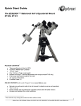
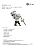
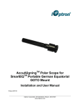
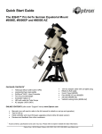
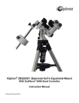
SkyGuider™ Tracking Equatorial Mount
Instruction Manual
Product #3500 and #3520
WARNING!
NEVER USE A TELESCOPE OR CAMERA TO LOOK AT THE SUN
WITHOUT A PROPER FILTER!
Looking at or near the Sun will cause instant and irreversible damage to your eye.
Children should always have adult supervision while observing.
1. SkyGuiderTM Tracking Equatorial
Mount Overview
Thank you for choosing the new iOptron SkyGuiderTM
Tracking equatorial mount for astrophotography. This
portable mount makes it easy to take long exposures of
the night sky without streaking or star trailing.
The SkyGuiderTM mount is simple to set up. Just attach
the mount to a tripod. Mount your digital camera or
lightweight scope onto the mount and balance it. Align
the mount to the Pole Star using the included
AccuAligningTM dark field illuminated polar scope and an
optional smart phone App. Then turn on the motor and it
will keep your camera tracking at the same speed the
earth rotates. The unique DC servo motor keeps your
camera in motion to avoid star trails and allows you to
take long exposures for beautiful images of the night
sky. A built-in ST-4 compatible guide port will enable you
to use autoguiding and make the tracking even better!
Features:
• Accepts cameras weighing up to 11 lbs (5 kg)
• Capable for dual mount application up to 11 lbs
(5kg) + 7.7lbs (3.5kg), balanced
• Spring loaded gear system with customer adjustable
loading force
• Auto-tracking for smooth camera motion perfect for
long-term exposures
• Four pre-set tracking speeds with northern/southern
hemisphere selection
• Includes iOptron AccuAligningTM dark-field
illuminated polar scope for Quick Polar Alignment
• Built-in ST-4 compatible guide port
• Padded carry bag included
• 1.5” stainless steel short field tripod with padded
carry bag (#3500 only)
• Optional ball heads available separately (#3305)
• Optional AC/DC adapter (#8417)
• Optional 1.5” stainless steel regular height tripod
(#3521)
DO NOT hold and swing the counterweight shaft
rigorously. This will degrade the performance of the
spring loaded gear meshing system and possibly
damage it.
The Tension Adjuster is used as the last step to
lock, and the first step to release the gears. When
disengaging the gear system, release the Tension
Adjuster first. Then turn the Gear Switch to OPEN
position. When engaging the gear system, turn the
Gear Switch to LOCK position first. Then tighten the
Tension Adjuster.
Never fully tighten the Tension Adjusters during
operations. Fully screw in the Tension Adjuster and
then back out by from half a turn to about 2 turns.
The optimum spot varies with actual conditions, but
is mostly within 2 turns from the fully tightened
position. Ideally, it should be at a position just deep
enough to eliminate any free movement (“play”),
while any force on the worm assembly is kept at a
minimum.
2. SkyGuiderTM Tracking Equatorial
Mount Assembly
2.1. Introduction
You have just purchased a tracking equatorial mount
that is capable of taking you to a new level of
astrophotography. When the polar axis of the
SkyGuiderTM mount is aligned with the celestial North
Pole (CNP), or celestial South Pole (CSP), the mount
will evenly match the Earth’s rotation against the sky.
Since all celestial objects appear to rotate around the
CNP, or CSP—the polar alignment allows the mount to
“track” with the celestial sphere and provide accurate
tracking for visual observations and astrophotography.
The AccuAligningTM polar scope, along with the Quick
Polar Alignment procedure, provides a fast and accurate
polar alignment for the mount. A built-in ST-4 compatible
guide port will enable you to use autoguiding for highperformance tracking.
The SkyGuiderTM mount is designed for wide field
astrophotography. The following sections of this manual
provide detailed steps to successfully set up and operate
the SkyGuiderTM mount.
2.2. Parts List1
ONLINE CONTENTS (click under “Support” menu)
www.iOptron.com
The SkyGuiderTM comes with either a mount only (#3520)
or as a package (#3500) with mount and a short field
tripod.
•
•
•
This manual
Tips for set up
Reviews and feedback from other customers
#3520 SkyGuiderTM Mount Includes (Figure 1):
2.3. Assembly Terms
• SkyGuiderTM Tracking equatorial mount with
AccuAligningTM polar scope
• Padded carry bag
• Counterweight shaft
• One 3.5 lbs (1.5kg) counterweight
• A short latitude adjust knob for low altitude
3/8”‐16 screw
Tension adjuster
DEC adapter
Polar axis cover
#3500 SkyGuiderTM Mount Package Includes (Figure
2):
Polar scope cover
CW
• #3520 SkyGuiderTM mount
• #3501 1.5” stainless steel short field tripod with
padded carry bag
DEC lock screw
Az. Adj. Screw
CW shaft
Center rod with knob
Tripod support tray
Tray locking knob
Figure 2. Parts for a #3500
SkyGuiderTM mount package
Figure 3. SkyGuideTM mount with tripod
Figure 1. Parts for a
#3520 SkyGuiderTM
mount
2.4. SkyGuiderTM EQ Mount Assembly
NOTE: The SkyGuiderTM mount is a precision
astronomical instrument. It is highly recommended
that you read the entire manual and become familiar
with the nomenclature and functions of all
components before starting the assembly.
ADDITIONAL PARTS NEEDED:
The following parts are needed to take astrophotography
but are not included in the package:
• Power source provided by a battery pack or an
AC/DC adapter (#8417)
• Ball head adapter (#3305)
• DLSR camera
• Tripod (for #3520)
WARNING: Please DO NOT hold and swing the
counterweight shaft rigorously. This will degrade the
performance of the spring loaded gear meshing
system and possibly damage it.
WARNING: The new Gear Switch will allow you to
have more precise weight balance. This also means
the mount will swing FREELY when the Gear Switch
is disengaged. Always hold the mount when
releasing the Gear Switch or adjusting the gear
tension.
YOU MAY NEED THIS FOR POLAR ALIGNMENT:
• iPhone/iPad app for accurate polar alignment
(https://itunes.apple.com/us/app/ioptron-polarscope/id564078961?mt=8)
• Or other application/program to calculate the
pole star position. Please refer to the FAQ
section under “Support” at
http://www.ioptron.com for more information.
1
NOTE: The mount is shipped with the latitude setting
at high range (35º ~ 60º). If your site latitude is lower
than 35º please switch the latitude range before
using.
US market only. Actual contents and appearances may vary.
3
to secure it with tripod. Tighten the Tray Locking Knob to
fully spread the tripod legs. Adjust the tripod legs to
level the mount using the Level Bubble.
STEP 1. Select Mount Latitude Range
Carefully remove the mount from the package and
familiarize yourself with the components shown in Error!
Reference source not found..
Alignment Peg
The mount is by default shipped with the Long Latitude
Adjustment Knob installed (for 35-60º). At lower
latitudes of 0-35º, the Short Latitude Adj. Knob needs to
be used. To change this knob, remove the Latitude
Locking T-bolts on both sides (Be careful not to lose the
washers). Unscrew Bottom Post Locking Screw to free
the Bottom Latitude Adj. Post and remove the Latitude
Adj. Knob. Thread in evenly the Short Latitude Adj. Knob
to Top and Bottom Latitude Adjustment Posts. Reinstall
and tighten bottom locking screw. Lastly, with 4 washers
all properly placed, insert and tighten the Latitude Locking
T-bolts into the upper threaded holes.
Azimuth
Adjustment Knob
(b)
Alignment Peg
Figure 5. Set up tripod and mount
STEP 3. Adjust Latitude
Short Lat. Adj. Knob
Level Bubble
This step requires you to know the latitude of your
current location. This can be found on the Internet, with
a GPS navigator or a GPS capable cell phone. You will
have to change this latitude setting every time you
significantly change your night sky viewing location. This
setting directly affects the mount’s tracking accuracy.
Lat. Locking T-bolt
Bottom Lat. Adj. Post
Locking Screw
Slightly loosen the Latitude Locking T-bolts. Turn
Latitude Adjust Knob to adjust the latitude until the arrow
points to your current latitude on the Latitude Indicator
(see Figure 4b). Relock the Latitude Locking T-bolts. At
this point, with the mount leveled and pointed north, and
the latitude set, the Polar Axis (R.A. axis) should be
pointing very close to the NCP and Polaris. This
alignment accuracy will be sufficient for visual tracking
and short duration astrophotography.
Latitude Indicator
Long Lat. Adj. Knob
For Low Latitude
For High Latitude
Azi. Adj. Knob
STEP 4. Install Counterweight (CW) shaft and CW
Thread the stainless
steel
counterweight
shaft onto the 3/8”-16
threaded hole on the
short arm of the DEC
Adapter. Remove CW
Safety Screw and slide
the CW onto the CW
shaft. Tighten the CW
Locking Screw to hold
the CW in place.
Tighten the CW Safety
Screw.
Figure 4. Switching latitude adjustment knobs
STEP 2. Setup Tripod and Mount
Expand the tripod legs and adjust the tripod height.
Position the tripod so that the Alignment Peg faces north,
(if you are located in the northern hemisphere). If you
are located in southern half—face the Alignment Peg
south. Thread the Tripod Center Rod into the tripod head.
Install the Tripod Support Tray and thread the Tray
Locking Knob onto it. Do not fully tighten the Tray
Locking Knob.
There are two threaded holes on the tripod head for
alignment peg installation. You may place the peg at
either position, as long as the mount does not hit the
tripod leg when tracking.
CW shaft
CW locking screw
CW
CW safety screw
Figure 6. CW shaft and CW
STEP 5. Balance the SkyGuiderTM Mount
After attaching an optional ball head and a camera or
telescope onto the mount, the SkyTracker mount must
be balanced to ensure minimum stress on the mount
gears and motors inside.
Retract both Azimuth Adj. Knobs to allow enough
clearance inside the chamber. Position the mount on the
tripod head with the Alignment Peg in between the 2
Azimuth Adj. Knobs. Thread the Center Rod into mount
4
those in the southern hemisphere, use Sigma Octantis in
Octans as the pole star.
CAUTION: The mount may swing freely when the
Gear Switch is released. Always hold on to the
mount before you release the gear switch to prevent
it from swinging. Otherwise it may cause personal
injury or damage to the equipment.
To locate the pole star from the polar scope, take off the
Polar Axis Cover and Polar Scope Cover. Look through
the polar scope eyepiece to locate Polaris (if you are
located in northern hemisphere). Slightly turn the tripod
Center Rod Knob to loosen the mount head. Adjust the
Azimuth Adjustment Knobs to do a fine adjustment of the
mount to center the pole star in the azimuth direction.
Tighten the Center Rod Knob to secure the mount.
Slightly loosen the two Latitude Locking T-bolts on the
side of the mount, turning the Latitude Adjustment Knob
to adjust the latitude (altitude). Re-tighten the locking
screws.
Turn the Tension Adjuster counterclockwise until the
Gear Switch Knob can be turned 90 degree to OPEN
position to disengage the worm from the worm wheel.
Tension Adjuster
The SkyGuiderTM mount is equipped with iOptron’s
AccuAligningTM dark field illuminated polar scope. You
can do a fast and accurate polar alignment with
iOptron’s Quick Polar Alignment procedure to
maximize the benefit of the iOptron polar scope.
Gear Switch
LOCK
OPEN
Figure 7. Gear switch and Tension Adjuster
Rotate the mount head along the R.A. axis to horizontal
position. Adjust the CW position to balance the mount.
LED thread
Figure 10. Threaded polar scope LED socket
Plug a power source to the mount. Connect the polar
scope LED to the mount by threading the polar scope
illuminating LED into the polar scope LED threading hole
(Figure 9). Plug the other end of the LED cable into the
LED socket located on the control board.
Figure 8. Balance a SkyGuiderTM mount
Press the power switch on the mount to turn the
SkyGuiderTM mount on. Look through the polar scope
eyepiece. Adjust the eyepiece to bring the reticle dial in
focus. As indicated in Figure 10, the Polar Scope Dial
has been divided into 12 hours along the angular
direction with half-hour tics. There are 2 groups, 6
concentric circles
marked from 36’
to 44’ and 60’ to
70’, respectively.
The 36’ to 44’
concentric circles
are used for polar
alignment in the
northern
hemisphere using
Polaris. While the
60’ to 70’ circles
are used for polar
alignment in the
Figure 9. Polar scope
CAUTION: The balancing must be performed while
the Gear Switch is disengaged (OPEN position).
Turn Gear Switch Knob 90 degree again to LOCK
position to re-engage the worm to the worm wheel.
Retighten the Tension Adjuster a few turns clockwise.
The rule of thumb is to fully screw in the Tension Adjuster and then back out by about 2 turns. The optimum spot varies with actual conditions which can be from half a turn to 2 turns. Ideally, it should be at a position just deep enough to eliminate any free movement (play) while force on the worm assembly is kept at a minimum. .
Step 6. Polar Alignment
In order for an equatorial mount to track properly, it has
to be polar aligned to the pole star. For those located in
the northern hemisphere, Polaris is the pole star. For
5
southern hemisphere using Sigma Octantis.
Using 0.5X Speed
You will need to know where Polaris is in the northern
hemisphere. You may find this information via an
iPhone/iPad app (iOptron Polar Scope in Apple iTune
store).
The 0.5X tracking speed evenly divides image blur
between the sky and foreground. With wide-angle
lenses, it can produce dramatic images of a starry sky
suspended above a landscape with everything sharp to
the eye.
Shown in Figure 11 is a screen shot of an iPhone chart.
For example, on December 3, 2012, 12:48:36 in Boston,
USA (Lat N42º30’28” and Long W71º08’49”), the Polaris
Position is 10hr 24.1m and r = 40.8min (the green dot on
the chart).
Advanced Application
The SkyGuiderTM mount is equipped with a guiding port
to enable autoguiding while tracking. The guide port
wiring is shown in Figure 13, which is same as that from
Celestron / Starlight Xpress / Orion Mount / Orion
Autoguider/ QHY5 autoguider pinout.
Adjust the mount in
latitude and azimuth
direction to place
Polaris in the same
position
on
the
Polar Scope Dial as
indicated on your
iPhone/iPad screen.
In this case, the
Polaris
will
be
located at a radius
of 40.8’ and an
angle of 10 hour
24.1 minute.
Figure 13. Guide port pinout
If you have an autoguider that has a pinout similar to STi of SBIG, such as Meade/ Losmandy/ Takahashi/ Vixen,
make sure a proper guiding cable is used with the
SkyGuiderTM mount. Refer to your guiding camera and
guiding software for detailed operation.
If you don’t have an
iPhone/iPad,
you
can still get a better
polar
alignment
using
other
programs/ software
to calculate the pole
star position.
The SkyGuiderTM mount is also capable of dual
camera/scope mounting as shown below.
Figure 11. iPhone display
STEP 7. Start Sky Tracking
Now you are ready to track the sky! Point the camera to
the sky you are interested in. You may also release two
DEC locking screws to rotate the DEC adapter along the
RA axis (Make sure all the screws/locks are tightened
afterwards). Select N or S (northern or southern
hemisphere) depending on your location. Select 1X
tracking speed to take photos of only the sky. Select
0.5X tracking speed to include landscape in the photo. S
and L speeds are for Solar and Lunar tracking. Double
check the polar alignment and realign it if needed. Turn
power switch on to begin tracking the sky.
Figure 14. Dual mounting
Additional accessories are needed for autoguiding and
dual mounting.
3. Maintenance and Servicing
3.1. Maintenance
The SkyGuiderTM equatorial mount is designed to be
maintenance free. Do not overload the mount. Do not
drop the mount. This will damage the mount or degrade
the tracking accuracy permanently. Use a damp cloth to
clean the mount if necessary. Do not use solvent.
Figure 12. SkyGuiderTM mount control board
6
3.2. iOptron Customer Service
3.3. Product End of Life Disposal
Instructions
If you have any question concerning your mount, contact
iOptron Customer Service Department. Customer
Service hours are 9:00 AM to 5:00 PM, Eastern Time,
Monday through Friday. In the unlikely event that the
mount requires factory servicing or repairing, write or call
iOptron Customer Service Department first to receive an
RMA# before returning the mount to the factory. Please
provide details as to the nature of the problem as well as
your name, address, e-mail address, purchase info and
daytime telephone number. We have found that most
problems can be resolved by e-mails or telephone calls.
Please contact iOptron first to avoid returning the mount
for repair.
This electronic product is subject to
disposal and recycling regulations that
vary by country and region. It is your
responsibility to recycle your electronic
equipment per your local environmental
laws and regulations to ensure that it will be recycled in
a manner that protects human health and the
environment. To find out where you can drop off your
waste equipment for recycling, please contact your local
waste recycle/disposal service or product representative.
It is recommended to send technical questions to
[email protected] or call in the U.S. 1.781.569.0200.
Technical Specifications
Mount
Payload (Max.)
Mount weight
Body material
Latitude adjustment range
Azimuth adjustment range
Worm wheel
Motor drive
Tracking
Tracking speed
Guiding port
Polar scope
Level indicator
Counterweight shaft
Counterweight
Power consumption
Power requirement
Base connect
Field Tripod
Operation Temperature
Warranty
Single Axis Tracking EQ
5kg + 3.5kg balanced
2.6kg w/o counterweight shaft
Cast aluminum
0º ~ 60º
± 10º
Φ88mm, 144 teeth aluminum alloy
DC servo motor with optical encoder
R.A. automatic
Cel, 1/2 Cel, Solar, Lunar, N/S
ST-4 compatible
TM
AccuAligning dark field illuminated (~6º FOV)
Level bubble
Φ20x200 mm, stainless steel w/ 3/8”-16 threads
1.5kg
0.05A at maximum load
DC 10 ~14V, 1Amp
3/8”-16 threaded socket
1.5”, 2 section stainless steel, 3.8kg (for #3500 only)
About 460~720mm in height, 510-800mm in length
-10ºC ~40ºC
One year limited
Rev.1.0
iOptron reserves the rights to revise this instruction without notice. Actual color/contents/design may differ from those described in this instruction.
7
IOPTRON ONE YEAR TELESCOPE, MOUNT, AND CONTROLLER WARRANTY
A. iOptron warrants your telescope, mount, or controller to be free from defects in materials and workmanship for one year. iOptron will repair or replace
such product or part which, upon inspection by iOptron, is found to be defective in materials or workmanship. As a condition to the obligation of iOptron
to repair or replace such product, the product must be returned to iOptron together with proof-of-purchase satisfactory to iOptron.
B. The Proper Return Merchant Authorization Number must be obtained from iOptron in advance of return. Call iOptron at 1.781.569.0200 to receive the
RMA number to be displayed on the outside of your shipping container.
All returns must be accompanied by a written statement stating the name, address, and daytime telephone number of the owner, together with a brief
description of any claimed defects. Parts or product for which replacement is made shall become the property of iOptron.
The customer shall be responsible for all costs of transportation and insurance, both to and from the factory of iOptron, and shall be required to prepay
such costs.
iOptron shall use reasonable efforts to repair or replace any telescope, mount, or controller covered by this warranty within thirty days of receipt. In the
event repair or replacement shall require more than thirty days, iOptron shall notify the customer accordingly. iOptron reserves the right to replace any
product which has been discontinued from its product line with a new product of comparable value and function.
This warranty shall be void and of no force of effect in the event a covered product has been modified in design or function, or subjected to abuse,
misuse, mishandling or unauthorized repair. Further, product malfunction or deterioration due to normal wear is not covered by this warranty.
IOPTRON DISCLAIMS ANY WARRANTIES, EXPRESS OR IMPLIED, WHETHER OF MERCHANTABILITY OF FITNESS FOR A PARTICULAR USE,
EXCEPT AS EXPRESSLY SET FORTH HERE. THE SOLE OBLIGATION OF IOPTRON UNDER THIS LIMITED WARRANTY SHALL BE TO REPAIR
OR REPLACE THE COVERED PRODUCT, IN ACCORDANCE WITH THE TERMS SET FORTH HERE. IOPTRON EXPRESSLY DISCLAIMS ANY
LOST PROFITS, GENERAL, SPECIAL, INDIRECT OR CONSEQUENTIAL DAMAGES WHICH MAY RESULT FROM BREACH OF ANY WARRANTY,
OR ARISING OUT OF THE USE OR INABILITY TO USE ANY IOPTRON PRODUCT. ANY WARRANTIES WHICH ARE IMPLIED AND WHICH
CANNOT BE DISCLAIMED SHALL BE LIMITED IN DURATION TO A TERM OF ONE YEAR FROM THE DATE OF ORIGINAL RETAIL PURCHASE.
Some states do not allow the exclusion or limitation of incidental or consequential damages or limitation on how long an implied warranty lasts, so the
above limitations and exclusions may not apply to you.
This warranty gives you specific legal rights, and you may also have other rights which vary from state to state.
iOptron reserves the right to modify or discontinue, without prior notice to you, any model or style telescope.
If warranty problems arise, or if you need assistance in using your telescope, mount, or controller contact:
iOptron Corporation
Customer Service Department
6E Gill Street
Woburn, MA 01801
www.ioptron.com
[email protected]
Tel. (781)569-0200
Fax. (781)935-2860
Monday-Friday 9AM-5PM EST
NOTE: This warranty is valid to U.S.A. and Canadian customers who have purchased this product from an authorized iOptron dealer in the U.S.A. or
Canada or directly from iOptron. Warranty outside the U.S.A. and Canada is valid only to customers who purchased from an iOptron Distributor or
Authorized iOptron Dealer in the specific country. Please contact them for any warranty.
8