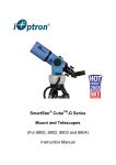
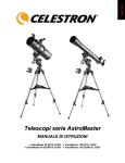
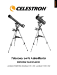
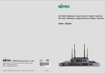
1
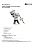
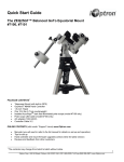
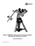
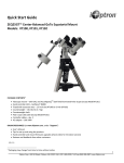
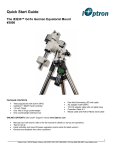
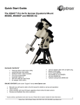
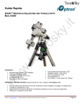
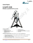
®
AccuAligningTM Polar Scope for
SmartEQTM Portable German Equatorial
GOTO Mount
Installation and User Manual
Product #3130
iOptron Corporation, 6E Gill Street, Woburn, MA 01801
www.iOptron.com
iOptron’s AccuAligningTM polar scope #3130 is an accessory for SmartEQ portable German
equatorial mount. It provides a fast and accurate polar axis alignment with Quick Polar Alignment
procedure.
Included in Package:
1X Polar scope #3130
1X Polar scope set screw
1X Polar scope illumination LED
2X M3 screw and nut
Polar Scope
LED
eyepiece
Figure 1. Parts list
Installation:
Install polar scope
1. Unscrew polar scope cover from the mount;
2. Insert included M4 set screw into the treaded hole on the polar scope housing, as show in
Figure 2. Use a hex key wrench to turn the screw few turns. Make sure the tip of the screw
does not penetrate into the hole, which will block the polar scope insertion.
Figure 2. Insert M4 set screw
2
3. Insert polar scope all the way into the scope housing, as shown in Figure 3. The polar scope
will be tight fitted into the scope house. Secure the scope by tightening the set screw.
2
1
Figure 3. Install polar scope
Install polar scope illumination LED
1. If there is a bar in the middle of the polar alignment opening as shown in the Figure 4, the
SmartEQ mount already has an illumination LED as part of the main control board. If you can’t
see through the polar alignment opening, it is blocked by the DEC axle. Please turn the mount
on and use the UP or DOWN arrow key on the hand controller to rotate the DEC axle until you
can see through the opening.
Figure 4. SmartEQTM with integrated polar scope illumination LED
Please go to the Operation part for polar alignment.
3
2. If there is no illumination LED installed, please follow the procedures bellow to install it.
Release four (4) screws from the SmartEQ face plate, as shown in Figure 5.
Motor cables
Battery cables
Figure 6. Disconnect cables
Figure 5. Remove face plate screws
3. Carefully pull the face plate open. Disconnect the RA and DEC motor drive cables first. Then
disconnect two battery holders from the main board.
4. Lay the face plate with main control board on a table. Align the illumination LED to the top edge
of the board, make sure plus (+) and minus (-) electrodes of the LED are aligned to the + and –
signs on the board, as shown in Figure 7.
Figure 7. Align LED to the main board
4
5. Secure the LED onto the control board using supplied screw and nut sets.
Figure 8. Secure the LED using screws and nuts
6. If you have an AC/DC power supply, you may connect the power supply and Go2Nova 8408
hand controller to the control board. Turn the power switch on and use hand controller Set
Polar Light command under Set Up Controller menu to adjust the LED brightness. Otherwise,
you may test it after install the face plate back to mount.
Figure 9. Adjust the LED brightness by a hand controller
7. Reconnect the battery plugs and R.A. and DEC motor controller cables. Place the face plate
back to the mount and screw it onto the mount.
Quick Polar Alignment:
1. Insert 8 AA batteries into the battery packs or connect the mount with an AC/DC power adapter.
Plug the Go2Nova hand controller into the mount HBX port. Turn the power switch on.
2. Make sure that the DEC axle is not blocking the polar scope view by turn the DEC axle using
UP or DOWN button. Press the Number key to change the speed.
3. Use hand controller Set Polar Light command under Set Up Controller menu to adjust the
LED brightness to a comfort level.
4. Adjust polar scope eyepiece shown in Figure 1 to bring the Polar Scope Dial in focus.
As indicated in Figure 10, the Polar Scope Dial has been divided into 12 hours along the
angular direction with half-hour tics. There are 2 groups, 6 concentric circles marked from 36’ to
44’ and 60’ to 70’, respectively. The 36’ to 44’ concentric circles are used for polar alignment in
northern hemisphere using Polaris. While the 60’ to 70’ circles are used for polar alignment in
southern hemisphere using Sigma Octantis.
5
Figure 11. Zero position mark
Figure 10. Polar Scope Dial
5. Release R.A. Clutch Screw. Press the LFTT or RIGHT button on the hand controller to rotate
the polar scope to align the 12 o’clock position of the dial on the top, as shown in Figure 10. (Or
align to the zero position mark on the R.A. unit as shown in Figure 11). You may press number
9 button to change the rotation speed to MAX.
6. Make sure that the time and site information of the hand controller is correct. Press the MENU
button, then select “Align” and “Pole Star Position” to display the current Polaris position. For
example, on May 30, 2010, 20:00:00 in Boston, United States (Lat N42º30’32” and Long
W71º08’50”, 300 min behind UT, DST set to Y), the Polaris Position is 1hr 26.8m and r = 41.5m,
as shown in Figure 12 (a).
7. Adjust the mount in altitude (latitude) and azimuth (heading) direction to place Polaris in the
same position on the Polar Scope Dial as indicated on the HC LCD. In this case, the Polaris will
be located at a radius of 41.5’ and an angle of 1 hour 26.8 minute, as shown in Figure 12 (b).
(a)
(b)
Figure 12. Place the Polaris at the position as shown on hand controller
You need to loose Azimuth Lock a little and use Azimuth Adjustment Knobs to adjust the mount
in azimuth (heading) direction (Figure 13). Unlock Latitude Clutch, and turn Latitude Adjustment
Screw or push the mount down to adjust the altitude (latitude), as shown in Figure 14. Secure
all the locks after the polar alignment is done.
Now the mount is polar aligned.
6
Azi. adj. knob (X2)
Latitude dial
Latitude
clutch
Latitude
Adj. Screw
Azimuth lock
Figure 14. Latitude Adjustment
Figure 13. Azimuth adjustment
Adjust Polar Scope Focuser
If the polar scope does not focus on the distant object, take the polar scope out of the mount
housing. Point the polar scope to a far distant object. Adjust the Objective Lens by turning the tube
to get a clear image. Tune the lock ring to secure it.
Replace the Polar Scope back to the mount and tighten it. Adjust the Eyepiece to get a clear
picture of the reticle.
Polar Scope Alignment:
Reticle Adj.
Screws
Eyepiece
Objective Lens
Locking Ring
If you are suspecting that the polar scope may be misaligned to the mount R.A. axis, you may
check it by putting a star in the center of the polar scope reticle cross hairs and rotating mount’s
R.A. axis. If the star stays in the center of cross hairs, the polar scope is aligned to the mount’s R.A.
axis.
In the event the polar scope optical axis needs to be adjusted, you can do this procedure at night
while pointing at Polaris. However, it is probably easier to do it during the daytime using a distant
point, such as a flag pole or top of a building a couple of hundreds away, as your target. Please
remove the telescope, the counterweights and counterweight shaft from the mount. Aim the mount
to the object. Use the Latitude Adjustment Screw and Azimuth Adjustment Knob to center the
object.
7
1. Release RA Clutch Screws. Rotate the
Bring the object
mount along the RA axis to the
half the distance
balance position, dovetail saddle on Center the object
to the center
the right side. Lock the RA clutch
screws.
2. Loose latitude Locking Screws and
Rotate
Azimuth Locking Screws a little.
Centering the object one the cross
hairs by adjust Latitude Adjust. screw
and Azi. Adjust. Knob.
3. Release the RA clutch again. Rotate
the mount 180º to bring the dovetail to
the left side. Retighten the RA clutch
screw. Bring the object half the
Rotate
distance to the center by adjusting the
reticle adjustment set screws using a
hex key. Keep in mind that the image
in the finder is inverted. Loose one
screw first, then tighten the other screw(s). Only loose/tighten one screw at a time and a
few turns each time to avoid the reticle totally lost its position. It may take a few minutes to
familiarize yourself with the screws that move the polar scope in the appropriate direction.
PLEASE do not over tighten the setting screws.
4. Release the RA clutch and rotate the mount 180º to bring the dovetail back to the right side.
If you are lucky enough, the object will stay in center of the polar scope. Otherwise, repeat
Steps 2 and 3 to further move the object to the center.
5. After few times, the object will stay in center when the mount is flipped from right to left.
x
x
September 10, 2012 V1.0
iOptron reserves the rights to revise this instruction without notice. Actual color/contents/design may differ from those described in
this instruction.
8