1
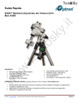
Quick Start Guide
The iEQ45™ GoTo German Equatorial Mount
#8000D, #8000DP and #8000AZ
PACKAGE CONTENTS1
•
•
•
•
•
•
•
•
Telescope Mount (with built-in GPS)
Losmandy/Vixen dual saddle
Go2Nova® 8407 Hand Controller
Two 5 kg Counterweight
Controller Cable X 2
LED with cable for Polar Scope
AC adapter (100V-240V)
12V DC adaptor cable with car lighter plug
•
•
•
•
•
•
•
RS232 cable
RS232 to RJ9 cable
2-inch Tripod (8000D)
Pier (8000AZ and 8000DP)
AZ base (8000AZ)
Vertical Locking Knob (8000AZ)
Polar axis cover with spirit level (8000AZ)
ONLINE CONTENTS (click under “Support” menu) www.iOptron.com
•
•
•
•
1.
Manuals (you will need to refer to the full manual for details on set-up and operation).
Tips for set up
Hand controller and mount firmware upgrades (check online for latest version)
Reviews and feedback from other customers
Actual contents, specifications and color may vary. Please refer to iOptron website for latest information.
1
iOptron Corp. | 6E Gill Street | Woburn, MA 01801 USA | (781) 935-2800 | Toll Free (866) 399-4587 | www.iOptron.com Quick Setup
Move the Pier Foot from the end to the side.
1. A. Setup tripod: Expand the tripod legs and lock the
Tripod Spreader so that the tripod legs stay open
(Figure 1). Adjust the tripod height by unlocking and
re-locking the tripod legs to desired height. Position
the tripod so that the Alignment Peg faces north. (The
Alignment Peg may be moved to the opposite
position if used at latitude lower than 20º to avoid
counterweights hitting the tripod leg)。
Pier Foot
Pier Foot
(Storage
Position)
Alignment Peg
Figure 4
Spread the Pier Leg. Put the Pier Tube onto the Pier
Base, with Pier Alignment Slot aligned over the
Alignment Tab on the Pier Base.
Tripod Spreader
Pier Leg
Align Slot
Tripod Lock
Figure 1
1.
B. Setup pier: Unthread the Pier Locking Screw
(This screw is only used for pier storage).
Separate the Pier Base with Legs from the Pier Tube.
Remove the Pull Rods from inside the pier.
Pier Locking
Screw
Pier Base
Pier Base
Align Tab
Figure 5
Adjust the length of the three Pull Rods. Hook one
end of a Pull Rod onto a bolt located on the Pier Leg
and the other Pull Rod end onto the mounting beam
inside the Pier Tube. Evenly tighten the Pull Rods.
Make sure there is no gap between the Pier Base
and Pier Tube.
Pier Tube
Figure 2
Pull Rods
Figure 3
2
iOptron Corp. | 6E Gill Street | Woburn, MA 01801 USA | (781) 935-2800 | Toll Free (866) 399-4587 | www.iOptron.com Tighten evenly
Alignment Peg
Figure 9
Adjustable Feet
3.
Figure 6
Position the pier with Alignment Peg face north.
Alignment Peg
Set the Latitude: Unlock the four R.A. Clutch Screws
and rotate the mount 180º around the R.A. axis
(Figure 10) to move the dovetail face upside. Tighten
the R.A. Clutch Screws. Un-screw the Altitude
Adjustment Lever from Altitude Adjustment Knob
(Figure 11). Turn the Latitude Adjustment Knob to
set your current Latitude, which is displayed in
Latitude Mark Window. Use the Lever for fine
adjustments as needed. Always set the latitude
without the load.
Dovetail Saddle
R.A. axis
Polar Axis
Figure 7
2.
Attach the EQ mount: Retract the Azimuth
Adjustment Knobs (next to the Bubble Level Indicator)
to allow enough clearance for the Alignment Peg
seating in the house. Put the mount onto the tripod
head (or pier top) with bubble level on top of the
Alignment Peg (Figure 9). Secure the mount head by
tightening two Azimuth Locking T-bolts (Figure 8).
Level the mount by adjusting individual tripod leg (or
pier foot). You may use the build-in Bubble Level
Indicator or an external torpedo level to check level.
R.A. Clutch
Screw (X4)
Lat. Locking Screw (X4)
Bubble Level
Figure 10
Lat. Mark Window
Azi. Locking T-bolt (x2)
Azi. Adjust. Knob
Plastic Washer
If your latitude is between 5º to 40º, set the Latitude
Adjustment Knob to the lower position. A Latitude
Safety Block has to be installed (Figure 11)
If your latitude is between 35º to 70º, take the Latitude
Safety Block off. Set the Latitude Adjustment Knob to
the upper position. You should change the position
before attaching the mount to the tripod head.
Figure 8
3
iOptron Corp. | 6E Gill Street | Woburn, MA 01801 USA | (781) 935-2800 | Toll Free (866) 399-4587 | www.iOptron.com Locking Screw
Lat. Safety Lock
7.
Connect cables: Attach one end of an RJ-11 cable
into the socket on the side of the DEC unit and the
other end into the DEC socket located on RA unit.
Use another RJ-11 cable to connect the hand
controller to the HBX socket located on the RA unit.
Plug 12V DC power supply into the POWER socket
on RA unit. The red LED will be on when the power
switch is turned on.
8.
Setup Controller: The time and site information of
the observation location needs to be entered for
precise GOTO.
Lat. Adjust. Knob
Upper Position
Lat. Adjust. Lever
Lower Position
Figure 11
4.
Turn the mount power on. Wait for controller lights on.
Press the MENU button. Move the cursor to “Set Up
Controller” and press ENTER. Select “Set Up Time
& Site” and press ENTER.
Attach counterweight (CW) shaft: Unscrew the CW
shaft from the top of the mount (Figure 12 top) and
thread it into the opening of the DEC axis (Figure 12
bottom).
Figure 13
Enter the date and check if it is Daylight Saving Time
using arrow keys and number keys. Enter your time
zone (add or subtract 60 minutes per time zone) by
entering minutes “behind” UT or “ahead of” UT, such
as:
• Boston is 300 minutes “behind” UT
• Los Angeles is 480 minutes “behind” UT
• Rome is 60 minutes “ahead of” UT
• Sydney is 600 minutes “ahead of” UT
All the time zones in North America are “behind” UT.
You may also find your observation longitude and
latitude coordinate from your GPS navigator, a GPS
capable cell phone or from internet. “W/E” means
western/eastern
hemisphere;
“N/S”
means
northern/southern hemisphere; “d” means degree; “m”
means minute; and “s” means second. Use number
keys and arrow keys to enter your location information.
Figure 12
5.
6.
Install counterweight(s): iEQ45 comes with two 5kg
counterweights. Use one or both of them for your
particular OTA (Optical Tube Assembly). An optional
CW shaft extension or additional CW is available for
purchase at www.ioptron.com.
Attach OTA to mount and balance: After attaching
an OTA and accessories to the mount, the iEQ45
must be balanced to ensure minimum stress on the
mount (such as gears and motors inside). There are
four (4) Clutch Screws on both DEC and R.A. axes.
Please refer to the full manual for balance
procedures/tips.
Move the cursor to the end of the screen to select
Northern or Southern Hemisphere.
9.
Polar alignment: In order for an equatorial mount to
track properly, it has to be accurately polar aligned.
With the proprietary AccuAligningTM Polar Scope and
Quick Polar Alignment procedure, you can do a fast
and accurate polar alignment.
4
iOptron Corp. | 6E Gill Street | Woburn, MA 01801 USA | (781) 935-2800 | Toll Free (866) 399-4587 | www.iOptron.com Polar axis adjustment: Loosen Azimuth Locking
T-Bolts, adjust the Azimuth Adjustment Knobs to
do a fine adjustment of the mount in the azimuth
direction. Tighten the locking T-bolts to secure the
mount. Loosen four Latitude Lock Screws on the
side of the mount, turning the Latitude Adjustment
Knob so that the latitude reading from the Latitude
Mark Window equals to your local latitude. Use
the Lever for a fine latitude adjustment. Re-tighten
the locking lock screws.
Quick Polar Alignment:
(1) Take off the Polar Axis Cover and Polar
Scope Cover;
(2) Thread the dark field illuminating LED into the
thread-in hole on a polar scope. Plug the LED
cable into the Reticle socket located on the
RA unit. The illumination intensity can be
adjusted using the HC via “Set Eyepiece
Light” function under “Set Up Controller”
menu;
(3) Use the “▲” or “▼” button to turn the DEC axis
to unblock the Polar Scope view (there is a
hole on the DEC axis). You may loosen the
DEC clutch to turn the DEC axis without
rotating the telescope;
Figure 14
(4) Use the “◄” or “►” button to turn the RA axis
to rotate the Polar Scope dial to a clock
position where 12 is at the top, as shown in
Figure 14. You may release the R.A. Locking
Screws and hold the OTA while turning the
R.A. axis;
(5) Press the MENU button, then select “Align”
and “Pole Star Position” to display the Pole
Star Position on the LCD screen. Shown in
Figure 15(a) is Polaris position in northern
hemisphere. For example, May 30, 2010,
20:00:00 in Boston, US (alt N42º30’32” and
long W71º08’50”), 300 min behind UT, the
Polaris Position is 1h26.8m and 41.5m.
(If you are located in the southern hemisphere,
Sigma Octantis will be used as the reference
for polar alignment.)
(a)
(b)
Figure 15
(6) Follow Polar Axis Adjustment procedure to
adjust the mount in altitude and azimuth
directions and put the Polaris in the same
position on the Polar Scope Dial as indicated
on the HC LCD, as shown in Figure 15 (b).
BrightStar Polar Alignment
If the mount is not equipped with a polar scope or the
pole star cannot be seen, you can use BrightStar
Polar Alignment procedure from the hand controller:
(1) Level the iEQ45 mount and set it at Zero Position.
Make sure the telescope is parallel to the pole
axis (R.A. axis) of the mount. If a finder scope is
used, adjust it to be parallel to the telescope
optical axis. Set correct R.A. and DEC back lash
numbers. An eyepiece with cross hairs is
recommended.
(2) Power on the mount. Press the MENU button,
then select “Align” and “Polar Alignment”. The
HC will display the azimuth and altitude position of
several bright stars near meridian. Select one that
is visible from the site as aligning Star A. Follow
the on screen instruction to move the Star A to the
center of the eyepiece with a combination of
Latitude Adjustment Knob and the “◄” or “►”
button. Press ENTER to confirm. Then select a
bright star that is close to the horizon as aligning
Star B. Center it using the Azimuth Adjustment
Knob and “◄” or “►” button (The “▲” and “▼”
buttons are disabled during the process). Press
ENTER to confirm.
(3) The telescope will point to Star A again and
repeat above steps until the error is minimum, or
at your decision. Press the BACK button to exit
alignment procedure.
10. Adjust the Mount to Zero Position: The Zero
Position is the position where the counterweight shaft
points to ground, telescope is at the highest position
with its axis parallel to the polar axis and the
telescope is pointing to the Celestial Pole. Loosen the
DEC and R.A. Clutches to adjust the mount to the
Zero Position. Tighten the screws after each
adjustment. Power the mount OFF/ON.
11. Manual Operation of the Mount: Now you can
observe astronomical objects using the arrow keys of
the Go2Nova® hand controller. Flip the I/O switch on
5
iOptron Corp. | 6E Gill Street | Woburn, MA 01801 USA | (781) 935-2800 | Toll Free (866) 399-4587 | www.iOptron.com the telescope mount to turn on the mount. Use
►,◄,▼ or ▲ buttons to point the telescope to the
desired object. Use the number keys to change the
slewing speed. Then press STOP/0 button to start
tracking.
12. Star Alignment: Star alignment will improve the
GOTO accuracy. From the main menu select “Align”.
Select “One Star Align” and press ENTER. The
screen will display “Adjust telescope to Zero
Position.” Press ENTER. A list of align stars that are
above the horizon is computed based on your local
time and location. Select a star and press ENTER.
Use arrow buttons to center the star in your eyepiece.
Use number keys to adjust the slew speed while
centering the object. (1 for slowest, 9 for maximum).
Press ENTER when finished. To increase the
accuracy you may choose to do multi-star alignment.
Note: two star alignment should be performed
after one star alignment.
13. Go to an Object: The mount is now ready to GOTO
and track targets. Press MENU button, select “Select
and Slew” and press ENTER. Select a category (ex.
“planets, sun, moon”). Then select an object (ex.
“moon”). Then press ENTER. The telescope will
automatically slew to the object and lock on. It will
automatically begin to track once it locks on to the
object.
14. Sync to Target: If the star is not in the center of the
eyepiece, one can use this function to center and
synchronize the object to improve the local GOTO
accuracy. Press MENU button and select “Sync. To
Target.” Press ENTER. Next use the arrow keys to
move object until it is centered in your eyepiece.
Then press ENTER again on the hand controller. A
Select and Slew has to be performed before “Sync
to Target” operation. This is most useful if you are
looking for some faint objects near a bright star.
“Sync to Target” is similar to “one star alignment”.
15. Identify Nearby Bright Objects: After slewing to an
object using hand controller, a list of nearby bright
object(s) will be displayed by pressing the “?” button.
washers in a safe place which will be needed when
converting the mount back to EQ mode.
Top Latitude
Locking Screws
Washer
Figure 16
19. Remove Latitude Adjustment Lever. Turn the Latitude
Adjustment Knob until it separates the top and bottom
latitude posts (Figure 17). Remove the other two
Latitude Locking Screws to separate the mount head
from the EQ base.
Latitude Adjustment
Knob
Figure 17
20. Remove the Latitude Scale, which is secured onto
the mount with a Fixing Screw, as shown in Figure
18. Do not break the plastic scale. These parts are
needed when converting the mount back to EQ mode.
Convert EQ to AA
Scale Fixing Screw
16. Remove the iEQ45 mount from a pier or tripod and
make sure it is positioned upright.
Latitude Scale
17. Remove Polar Scope Cover and unthreaded Polar
Scope from the mount.
18. Lay down the mount head and unscrew top two (2)
Latitude Locking Screws (Figure 16). Keep two metal
Brass Washer
6
iOptron Corp. | 6E Gill Street | Woburn, MA 01801 USA | (781) 935-2800 | Toll Free (866) 399-4587 | www.iOptron.com Adjustable Washer
Figure 18
21. Thread Vertical Locking Nut onto the top brass
latitude post of the mount (Figure 19).
Figure 21
Vertical Locking Nut
24. Align the mounting holes on the AZ base to the
Latitude Locking Screw holes on the mount head.
Insert 4 Latitude Locking Screws into them. Tighten
the Adjustable Washers. Loosely tighten 4 Latitude
Locking Screws. Tighten the Vertical Locking Nut.
Then tighten the Latitude Locking Screws.
Latitude Locking
Screws
Figure 19
22. Retract two Adjustable Washers on the AZ base
(Figure 20).
Vertical
Locking Nut
Open slot
Figure 22
Adjustable
Washer
25. Replace the Polar Axis Cover with the one with a
spirit bubble level.
Spirit Level
AZ base
Figure 20
23. Place the AZ base onto the mount head with Vertical
Locking Nut placed in the open slot on AZ base
(Figure 21). Be careful that the mount will be bottom
heavy.
Figure 23
26. Install the mount onto the pier/tripod top. Level the
mount by adjusting the tripod legs or pier feet (Refer
7
iOptron Corp. | 6E Gill Street | Woburn, MA 01801 USA | (781) 935-2800 | Toll Free (866) 399-4587 | www.iOptron.com to STEP 1). Use the spirit bubble level on the Polar
Axis Cover.
29. Connect the hand controller, DEC cable and power
supply and turn the mount on.
27. Attach your telescope onto the mount. Add
counterweight(s) to balance the scope. You may do a
rough torque calculation to determine the CW
quantity and position. Or if you’re using in EQ mode -mark the position. The mount can only hold a light
payload without counterweight(s). Double check the
leveling of the system.
30. Set the hand controller by following the iEQ45 initial
set up for time and site information. Set the mount to
ALT-AZI mode. Power the mount OFF/ON to
complete the mode switching.
28. Release four R.A. clutch screws. Adjust the mount so
that the CW shaft is pointed to East and the
telescope is on the West side of the mount. Adjust
the telescope to point to Zenith. This is “Zero
Position” for operating in AA mode.
Zenith
EAST
Figure 25
31. Use “One Star Align” to correct any initial
misalignment. Or use “Select and Slew” to a known
star, loosen the AZI (RA) and ALT(DEC)
clutch/screws, push the mount to center the star in
the eyepiece, relock the clutch/screws. Now your
mount is ready to go.
R.A. Clutch
Screws
Figure 24
For technical support you can email
[email protected]
May 2013, V2.0
8
iOptron Corp. | 6E Gill Street | Woburn, MA 01801 USA | (781) 935-2800 | Toll Free (866) 399-4587 | www.iOptron.com IOPTRON TWO YEAR TELESCOPE, MOUNT, AND CONTROLLER WARRANTY
A. iOptron warrants your telescope, mount, or controller to be free from defects in materials and workmanship for two years. iOptron will
repair or replace such product or part which, upon inspection by iOptron, is found to be defective in materials or workmanship. As a
condition to the obligation of iOptron to repair or replace such product, the product must be returned to iOptron together with proof-ofpurchase satisfactory to iOptron.
B. The proper Return Merchant Authorization (RMA) number must be obtained from iOptron in advance of return. Contact iOptron via email at [email protected] or call at 1.781.569.0200 to receive the RMA number to be displayed on the outside of your shipping
container.
All returns must be accompanied by a written statement stating the name, address, and daytime telephone number of the owner,
together with a brief description of any claimed defects. Parts or product for which replacement is made shall become the property of
iOptron.
The customer shall be responsible for all costs of transportation and insurance, both to and from the factory of iOptron, and shall be
required to prepay such costs.
iOptron shall use reasonable efforts to repair or replace any telescope, mount, or controller covered by this warranty within thirty days of
receipt. In the event repair or replacement shall require more than thirty days, iOptron shall notify the customer accordingly. iOptron
reserves the right to replace any product which has been discontinued from its product line with a new product of comparable value and
function.
This warranty shall be void and of no force of effect in the event a covered product has been modified in design or function, or
subjected to abuse, misuse, mishandling or unauthorized repair. Further, product malfunction or deterioration due to normal wear is not
covered by this warranty.
IOPTRON DISCLAIMS ANY WARRANTIES, EXPRESS OR IMPLIED, WHETHER OF MERCHANTABILITY OF FITNESS FOR A
PARTICULAR USE, EXCEPT AS EXPRESSLY SET FORTH HERE. THE SOLE OBLIGATION OF IOPTRON UNDER THIS LIMITED
WARRANTY SHALL BE TO REPAIR OR REPLACE THE COVERED PRODUCT, IN ACCORDANCE WITH THE TERMS SET FORTH
HERE. IOPTRON EXPRESSLY DISCLAIMS ANY LOST PROFITS, GENERAL, SPECIAL, INDIRECT OR CONSEQUENTIAL
DAMAGES WHICH MAY RESULT FROM BREACH OF ANY WARRANTY, OR ARISING OUT OF THE USE OR INABILITY TO USE
ANY IOPTRON PRODUCT. ANY WARRANTIES WHICH ARE IMPLIED AND WHICH CANNOT BE DISCLAIMED SHALL BE LIMITED
IN DURATION TO A TERM OF TWO YEARS FROM THE DATE OF ORIGINAL RETAIL PURCHASE.
Some states do not allow the exclusion or limitation of incidental or consequential damages or limitation on how long an implied
warranty lasts, so the above limitations and exclusions may not apply to you.
This warranty gives you specific legal rights, and you may also have other rights which vary from state to state.
iOptron reserves the right to modify or discontinue, without prior notice to you, any model or style telescope.
If warranty problems arise, or if you need assistance in using your telescope, mount, or controller contact:
iOptron Corporation
Customer Service Department
6F Gill Street
Woburn, MA 01801
www.ioptron.com
[email protected]
Tel. (781)569-0200
Fax. (781)935-2860
Monday-Friday 9AM-5PM EST
NOTE: This warranty is valid to U.S.A. and Canadian customers who have purchased this product from an authorized iOptron dealer in
the U.S.A. or Canada or directly from iOptron. Warranty outside the U.S.A. and Canada is valid only to customers who purchased from
an iOptron Distributor or Authorized iOptron Dealer in the specific country. Please contact them for any warranty.
9
iOptron Corp. | 6E Gill Street | Woburn, MA 01801 USA | (781) 935-2800 | Toll Free (866) 399-4587 | www.iOptron.com