1
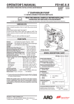
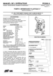
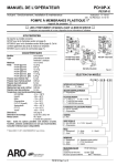
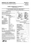
OPERATOR’S MANUAL
LM2250E-X-B
INCLUDING: SPECIFICATIONS, SERVICE KITS, GENERAL INFORMATION, PARTS, TROUBLESHOOTING
INCLUDE MANUAL: S-633 GENERAL INFORMATION (PN 97999-625)
RELEASED:
REVISED:
(REV. K)
6-1-00
6-11-10
LM2250E-( )-B
CHOP-CHECK GREASE PUMP
2” AIR MOTOR
50:1 RATIO
0 - 7500 P.S.I. RANGE
READ THIS MANUAL CAREFULLY BEFORE INSTALLING,
OPERATING OR SERVICING THIS EQUIPMENT.
It is the responsibility of the employer to place this information in the hands of the operator. Keep for future reference.
PUMP DATA
SERVICE KITS
• Use only genuine AROR replacement parts to assure compatible
MODEL LM2250E-X-B
pressure rating and longest service life.
• 637332 Pump Rebuild Kit. Includes the necessary soft parts for
normal service of the entire pump.
SPECIFICATIONS
Model Series . . . . . . . . . . . . . . . . . . . . LM2250E-X-B
Type . . . . . . . . . . . . . . . . Air Operated, Chop-Check Grease Pump
Ratio . . . . . . . . . . . . . . . . . . . . . . . . . . 50:1
Air Motor Diameter . . . . . . . . . . . . . . . 2” (5.08 cm)
Stroke . . . . . . . . . . . . . . . . . . . . . . . . . 3” (7.62 cm)
Air Inlet (female)
LM2250E-X1-B . . . . . . . . . . . . . . . 1/4 - 18 N.P.T.F. - 1
LM2250E-X2-B . . . . . . . . . . . . Rc 1/4 (1/4 - 19 BSP Taper)
Material Outlet (female)
LM2250E-X1-B . . . . . . . . . . . . . . . . . . 3/8 - 18 N.P.T.F. - 1
LM2250E-X2-B . . . . . . . . . . . . . . . Rc 3/8 (3/8 - 19 BSP Taper)
Pump Construction . . . . . . . . . . . . . Carbon Steel
Dimensional Data . . . . . . . . . . . . . . . . see chart
Weight . . . . . . . . . . . . . . . . . . . . . . . . . see chart
Air Inlet (female)
See “Specifications”
1-1/4”
(31.8 mm)
Material Outlet (female)
See “Specifications”
2” N.P.S.M. Bung Adapter
(not included with LM2250E-6X-B)
“A”
“B”
Figure 1
PERFORMANCE
Air Inlet Pressure Range . . . . . . . . . . . 0 - 150 p.s.i. (0 - 10.3 bar)
Fluid Pressure Range . . . . . . . . . . . 0 - 7500 p.s.i. (0 - 517.2 bar)
Cycles / Minute Rec’d @ Working Flow 80
Displacement In3 Per Cycle . . . . . . . . . 0.300
Volume / Cycle . . . . . . . . . . . . . . . . . . . 0.17 oz. (4.91 ml)
Maximum Delivery / Minute . . . . . . . . . 9 lbs (4.1 kg)
Noise Level @ 100 p.s.i. . . . . . . . . . . . . 85 db(A)*
Accessories Available . . . . . . . 61113 Wall Mount Bracket
66073-1 Air Line Connection Kit
* The pump sound pressure level has been updated to an Equivalent Continuous Sound
Level (LAeq) to meet the intent of ANSI S1. 13-1971, CAGI-PNEUROP S5.1 using four
microphone locations.
GENERAL DESCRIPTION
Model LM2250E-X-B Series chop-check grease pump is intended to be
used primarily for grease delivery systems. It uses carbon steel and other materials which make it compatible with most petroleum based lubrication products.
NOTE: If this pump was purchased separately (not part of a system),
consult your sales representative for compatible dispensing accessories which will best match the application. All accessories must be able
to withstand the maximum pressure developed by the pump.
INGERSOLL RAND COMPANY LTD
209 NORTH MAIN STREET – BRYAN, OHIO 43506
(800) 495-0276 FAX(800) 892-6276
www.ingersollrandproducts.com
© 2010
CCN 99879389
5/16” (8 mm) Thru hole
NOTE: Dimensions are shown in inches and (mm), supplied for reference only and are typically
rounded up to the nearest 1/16 inch.
MODEL
LM2250E-2X-B
LM2250E-3X-B
LM2250E-4X-B
LM2250E-6X-B
LM2250E-7X-B
LM2250E-8X-B
“A” (mm)
27-13/16” (705)
40-9/16” (1029)
49-1/16” (1245)
30-9/16” (775)
38-13/16” (985)
48-1/16” (1220)
“B” (mm)
16-9/16” (421)
29-5/16” (744)
37-13/16” (960)
19-5/16” (490)
27-9/16” (700)
36-13/16” (935)
WEIGHT (kg)
15 (6.8)
19 (8.6)
21.5 (9.8)
15.9 (7.2)
18.3 (8.3)
21.2 (9.6)
IMPORTANT
This is one of two documents which support the pump. Replacement copies of these forms are available upon request.
= LM2250E-X-B MODEL OPERATOR’S MANUAL
- S-633 GENERAL INFORMATION LUBRICATION PISTON PUMPS
WARNING READ THE GENERAL INFORMATION MANUAL
INCLUDED FOR ADDITIONAL OPERATING AND SAFETY PRECAUTIONS AND OTHER IMPORTANT INFORMATION.
PARTS LIST / LM2250E-XX-B
Item
1
2
n3
4
n5
n6
7
n8
n9
10
11
Description (size in inches)
Carriage Bolt (1/4” - 20 x 9” long)
Upper Cap
Gasket
Sleeve
“O” Ring (1/16” x 11/16” o.d.)
“O” Ring (1/8” x 3/4” o.d.)
Spool
“U” Cup (1/8” x 3/4” o.d.)
“O” Ring (.106” x .587” o.d.)
Cylinder
Adapter - models LM2250E-X1-B
- models LM2250E-X2-B
n 12
14
15
16
17
n 18
19
20
n 21
22
n 23
n 24
25
26
27
“O” Ring (1/16” x 3/4” o.d.)
“O” Ring (1/16” x 7/16” o.d.)
Muffler Housing
Foam Liner
Retaining Ring
Washer
“U” Cup (3/16” x 2” o.d.)
Piston
Piston Adapter
“O” Ring (3/32” x 1” o.d.)
Dowel Pin (1/4” o.d. x 7/8” long)
“O” Ring (3/32” x 13/16” o.d.)
Rod Seal
Washer
Spring
Base
models LM2250E-X1-B
28
29
n 30
31
Nut (1/4” - 20)
Ground Screw (#10 - 32 x 1/4”)
Gasket
Extension Tube
n 13
models LM2250E-X2-B
models LM2250E-2X-B (7.531’’)
models LM2250E-3X-B (20.281’’)
models LM2250E-4X-B (28.781’’)
Qty
(4)
(1)
(2)
(2)
(4)
(4)
(2)
(2)
(2)
(1)
(1)
(1)
(1)
(1)
(1)
(2)
(1)
(1)
(2)
(1)
(1)
(1)
(1)
(1)
(1)
(1)
(1)
(1)
(1)
(4)
(1)
(1)
Part No.
94333
94307
94311
94316
Y325-15
Y325-206
94310
Y240-7
15066-PM
94249
94447
94447-1
Y325-16
Y325-11
94443
94402
94406
94515
Y240-23
94780
94388
Y325-117
Y148-37
Y325-114
95139
94785
94705
67241
67241-1
93828
93005
70834
(1) 94401-2
(1) 94401-3
(1) 94401-4
[Mtl]
[C]
[Z]
[B]
[Br]
[B]
[B]
[D]
[B]
[B]
[A]
[C]
[C]
[B]
[B]
[A]
[C]
[C]
[B]
[D]
[C]
[B]
[C]
[B]
[U]
[C]
[C]
[C/Z]
[C/Z]
[SS]
[C]
[Co]
[C]
[C]
[C]
Item Description (size in inches)
n 32
33
34
n 35
36
37
38
39
40
n 41
42
n 43
n 44
n 45
46
n 47
48
49
50
n 51
52
K 53
K 54
K
n
n
Qty Part No.
models LM2250E-6X-B (10.281’’)
(1) 94401-6
models LM2250E-7X-B (18.531’’)
(1) 94401-7
models LM2250E-8X-B (27.781’’)
(1) 94401-8
Gasket
(1) 70837
Piston Rod
(1) 95137
Pin
(1) 94786
Cotter Pin (1/16” x 1/2” long)
(1) Y15-21
Connector - LM2250E-2X-B (3.457”) (1) 94340-2
models LM2250E-3X-B (16.207”)
(1) 94340-3
models LM2250E-4X-B (24.707”)
(1) 94340-4
models LM2250E-6X-B (6.207”)
(1) 94340-6
models LM2250E-7X-B (14.457”)
(1) 94340-7
models LM2250E-8X-B (27.707”)
(1) 94340-8
Piston & Tube Ass’y (includes 37 - 39) (1) 67249
Lower Suction Tube
(1)
Plunger
(1)
Ball Stop
(1) 83276
Ball (9/32” dia.)
(1) Y16-209
Guide Washer
(1) 95131
Spacer
(1) 72392-1
Retaining Ring (.877” o.d.)
(1) 76243-1
“U” Cup (1/8” x 13/16” o.d.)
(1) Y186-54
Guide
(1) 95132
Foot Valve Body
(1) 95133
Foot Valve Ass’y (includes 43 - 46) (1) 67242
Gasket
(1) F21-65
Valve Seat
(1) 6797
Primer Rod
(1) 95134
Primer
(1) 94400
Retainer Ring
(1) 94397
Primer Tube
(1) 94399
Bung Assembly (includes 54)
(1) 67145-2
Thumb Screw (1/4” - 20 x 1”)
(3) Y66-59-C
Not included with models LM2250E-6X-B
Darina “EP” 2 Grease Packet
(1) 94833
Parts in Repair Kit
637332
[Mtl]
[C]
[C]
[C]
[Co]
[C]
[C]
[C]
[C]
[C]
[C]
[C]
[C]
[C]
[C]
[C]
[C]
[C]
[Co]
[C]
[C]
[B]
[T]
[SH]
[Co]
[C]
[C]
[C]
[C]
[C]
[ZA]
[C]
OPERATING AND SAFETY PRECAUTIONS
WARNING EXCESSIVE INLET PRESSURE. Can cause explosion resulting in severe injury or death. Do not exceed maximum operating pressure of 7500 p.s.i. (517 bar) at 150 p.s.i.
(10.3 bar) inlet air pressure. Do not run pump without using a
regulator to limit air supply pressure to the pump.
WARNING EXCESSIVE MATERIAL PRESSURE. Can cause
equipment failure resulting in severe injury or property damage. Do not exceed the maximum material pressure of any
component in the system.
Replacement warning label is available upon request, PN \ 94520.
Page 2 of 4
PUMP RATIO X
INLET PRESSURE TO PUMP MOTOR
=
MAXIMUM PUMP
FLUID PRESSURE
Pump ratio is an expression of the relationship between the pump motor area and
the lower pump end area. EXAMPLE: When 150 p.s.i. (10.3 bar) inlet pressure is
supplied to the motor of a 50:1 ratio pump it will develop a maximum of 7500 p.s.i.
(517 bar) fluid pressure (at no flow) -- as the fluid control is opened, the flow rate will
increase as the motor cycle rate increases to keep up with the demand.
NOTICE: Thermal expansion can occur when the fluid in the material lines is exposed to elevated temperatures. Example: Material
lines located in a non-insulated roof area can warm due to sunlight.
Install a pressure relief valve in the pumping system.
LM2250E-X-B
PARTS LIST / LM2250E-XX-B
30
1
6
31 ,
7
2
8
32
3
9
4
5
37 ,
13
10
12
33
. 11
34
35
36 ,
14
15
9
5
8
4
MATERIAL CODE
[A] = Aluminum
[B] = Nitrile
[Br] = Brass
[C] = Carbon Steel
[Co] = Copper
[D] = Acetal
[N] = Neoprene
[SH] = Hard Stainless Steel
[SS] = Stainless Steel
[T] = PTFE
[U] = Polyurethane
[Z] = Zinc
[ZA] = Zinc / Aluminum Alloy
38
7
16
17
6
18
39
19
41
43
18
45
47
40
42
44
46
48
20
21
22
23
3
49 ,
50
51
52 ,
28 ,
29
27
24
. TORQUE REQUIREMENTS ,
(11) 80 in. lbs (9.0 Nm) maximum.
(28) 80 in. lbs (9.0 Nm).
(31, 37, 52) 65 ft lbs (88.1 Nm) minimum.
(36) 17 - 25 ft lbs (23.1 - 33.9 Nm).
(49) 70 - 100 in. lbs (7.9 - 11.3 Nm).
LM2250E-X-B
25
54
26
53
Figure 2
Page 3 of 4
NOTE: All threads are right hand. Refer to figure 2 (page 3). Disconnect air supply and relieve all system pressure prior to servicing.
Carefully remove the parts, inspect for damage, nicks or excessive wear
and determine if any parts will need replacement.
1. Using a 7/8” wrench, unthread and remove (11) adapter, containing (12
and 13) “O” rings, releasing (14) muffler housing.
2. Using a 7/16” wrench, remove (28) nuts.
3. Remove four (1) bolts, (2) upper cap and (3) gasket.
4. Remove (10) cylinder, containing (4) sleeves and (7) spools.
5. Using (1) bolt, push (7) spools and (4) sleeves out “sleeve” end of
(10) cylinder.
6. Remove (16) retaining ring, (17) washer and (19) piston.
7. Remove (22) dowel pin, releasing (20) piston adapter.
8. Remove (3) gasket.
9. Clamp (31) extension tube horizontally in a vise. Unthread and remove (27) base, (30) gasket, (26) spring and (25) washer. NOTE:
Remove (24) rod seal only if replacement is necessary.
10. Pull up on (33) piston rod to reveal (35) cotter pin.
11. Remove (35) cotter pin and (34) connecting pin, releasing (33) piston rod.
12. Using (33) piston rod, push down on (36) connector until it bottoms.
13. Remove (51) retainer ring.
14. Push (50) primer up into (52) primer tube.
15. Lightly wedge a flat blade screwdriver between (50) primer and (52)
primer tube, so (50) primer unthreads with (52) primer tube.
16. Insert a 5/16” diameter rod thru the cross holes in (52) primer tube
and use the rod to unthread and remove (52) primer tube.
17. Remove (42) spacer, (47) gasket and (48) valve seat from (52) primer tube.
18. Remove (43 - 46) foot valve assembly from (49) primer rod.
19. Remove (43) retaining ring, releasing (44) “U” cup. NOTE: Do not
remove (45) guide unless replacement is necessary.
20. Remove (41) guide washer.
21. Clamp (37) lower suction tube horizontally in a vise. Unthread and
remove (31) extension tube and (32) gasket.
22. Using a 7/32” diameter rod in the cross hole in (36) connector and a
9/16” wrench on the flats of (38) plunger, unthread and remove (36)
connector from (38) plunger. NOTE: Do not damage the o.d. of (38)
plunger in any way.
23. Using a 5/32” diameter rod in the cross hole of (49) primer rod and a
9/16” wrench on flats of (38) plunger, unthread and remove (49)
primer rod, releasing (40) ball and (39) ball stop.
3. Assemble (45) guide and (44) “U” cup into (46) valve body, securing
with (43) retaining ring. NOTE: Assemble chamfered corner of (45)
guide into (46) valve body first.
4. Assemble (41) guide washer and (43 - 46) foot valve assembly onto
(49) primer rod.
5. Assemble (42) spacer, (47) gasket and (48) valve seat onto (49)
primer rod.
6. Thread (50) primer onto (49) primer rod, securing with (51) retainer
ring.
7. Thread (52) primer tube to (37) lower suction tube and tighten.
NOTE: Torque (52) primer tube to 65 ft lbs (88.1 Nm).
8. Assemble (33) piston rod to (36) connector, securing with (34) connecting pin and (35) cotter pin.
9. Assemble (32) gasket and (31) extension tube to (37) lower suction
tube and tighten. NOTE: Torque (31) extension tube to 65 ft lbs (88.1
Nm).
10. Assemble (23) “O” ring, (24) rod seal, (25) washer, (26) spring and
(30) gasket into (27) base and assemble (27) base to (31) extension
tube. Clamp (27) base horizontally in a vise and tighten (31) extension tube. NOTE: Torque (31) extension tube to 65 ft lbs (88.1 Nm).
11. Push up on (50) primer, exposing (33) piston rod.
12. Assemble (3) gasket to (27) base.
13. Assemble (21) “O” ring to (20) piston adapter and assemble (20) piston adapter to (33) piston rod, securing with (22) dowel pin.
14. Replace (18) “U” cups on (19) piston and assemble (19) piston onto
(20) piston adapter, securing with (17) washer and (16) retaining
ring.
15. Replace (5) “O” rings on (4) sleeves and assemble (4) sleeves into
(10) cylinder. NOTE: Assemble each sleeve into the end of the cylinder nearest the exhaust hole.
16. Replace (6 and 9) “O” rings and (8) “U” cups on (7) spools and assemble (7) spools into (10) cylinder from the opposite end as the (4)
sleeve went in.
17. Assemble (10) cylinder onto the pump, being careful when sliding
over the lips of (18) “U” cups. NOTE: Be sure (3) gasket is seated
properly.
18. Replace (3) gasket on (2) upper cap and assemble (2) upper cap to
(10) cylinder.
19. Assemble (1) bolts to pump, securing with (28) nuts. NOTE: Torque
(28) nuts to 80 in. lbs (9 Nm).
20. Replace (12 and 13) “O” rings on (11) adapter.
21. Assemble (15) foam liners to (14) muffler housing.
22. Assemble (14) muffler housing to (10) cylinder, securing with (11)
adapter. NOTE: Torque (11) adapter to 80 in. lbs (9.0 Nm).
PUMP REASSEMBLY
TROUBLE SHOOTING
NOTE: Thoroughly clean and lubricate all seals and bores with
Shell Darina “EP” 2 upon assembly. Replace all soft parts with new
ones included in the repair kit. Note: Refer to the illustration (figure 2,
page 3) for “U” cup lip seal direction.
1. Assemble (39) ball stop and (40) ball into (38) plunger, securing with
(49) primer rod. NOTE: Torque (49) primer rod to 70 - 100 in. lbs (7.9
- 11.3 Nm).
2. Thread (36) connector to (38) plunger, using a 7/32” diameter rod
thru the cross hole to tighten. NOTE: Tighten (36) connector to 17 25 ft lbs (23.1 - 33.9 Nm).
If the pump will not cycle or will not deliver material.
• Be certain to check for non-pump problems including kinked, restrictive or plugged inlet / outlet hose or dispensing device. Depressurize
the pump system and clean out any obstructions in the inlet / outlet
material lines.
• Check all seals, including track gaskets.
• Check direction of “U” cup lips.
PUMP DISASSEMBLY
PN 97999-914
Page 4 of 4
LM2250E-X-B