1
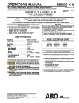
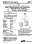
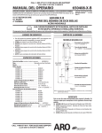
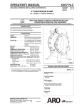
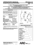
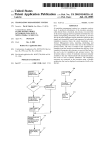
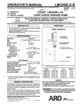
650453-X
OPERATOR’S MANUAL
INCLUDING: OPERATION, INSTALLATION & MAINTENANCE
RELEASED: 10-24-92
REVISED:
1-6-03
(REV. G)
ALSO INCLUDE MANUALS: 6544X-X (PN 97999-64) AIR MOTOR & S-632 GENERAL INFORMATION
MANUAL (PN 97999-624)
4-1/4” AIR MOTOR
9:1 RATIO
2-BALL BASIC PUMP
4” STROKE
650453-X
READ THIS MANUAL CAREFULLY BEFORE INSTALLING,
OPERATING OR SERVICING THIS EQUIPMENT.
It is the responsibility of the employer to place this information in the hands of the operator. Keep for future reference.
SERVICE KITS
PUMP DATA
• Use only genuine AROR replacement parts to assure compatible
MODELS 650453-X
pressure rating and longest service life.
• 61268 for repair of air motor section.
• 637177 for repair of lower pump end of models 650453-5 and
650453-11.
• Order lower pump end service parts separately for models
650453-7, 650453-8, 650453-9 and 650453-10.
Air Inlet (female)
1/2 - 14 N.P.T.F. - 1
65445-B Air Motor
(see 6544X-X manual)
GENERAL DESCRIPTION
• The ARO 9:1 ratio basic pump assembly consists of a 4-1/4” air mo-
tor, spacer section and two-ball lower pump end. The 4-1/4” air motor is a reciprocating type with pneumatic control circuit and
reversing valve. No working springs or piston connected trip rods
are used to reverse the air motor piston.
SPACER SECTION
• The air motor is connected to the lower pump end with a spacer tube
and solvent cup. This allows for lubrication of the upper packing
gland and to prevent air motor contamination because of normal
wear and eventual leakage through the material packing gland.
LOWER PUMP END
• The two-ball design provides for easy priming of the lower foot valve
and the double acting feature is standard in all ARO industrial
pumps. Material is delivered to the pump discharge outlet on both
the up and down stroke.
RATIO X REGULATED AIR PRESSURE TO AIR MOTOR = MAXIMUM
FLUID PRESSURE.
• The 9:1 ratio is on expression of the relationship between the air motor area and the lower pump end area. When 150 p.s.i. (10.3 bar) air
pressure is supplied to the air motor, the lower pump end will develop a maximum of 1,350 p.s.i. (93.1 bar) fluid pressure (at no flow). As
the fluid control is opened, the flow rate will increase as the air motor
cycle rate increases to keep up with the demand.
“A”
Material Outlet (female)
3/4 - 14 N.P.T.F. - 1
“B”
FIGURE 1
“C”
OPERATING PRECAUTIONS
• DO NOT exceed maximum working pressure of 1,350 p.s.i. (93.1
bar) at 150 p.s.i. (10.3 bar) air inlet pressure. HEED ALL WARNINGS.
• WARNING: HIGH PRESSURE DEVICE. Improper usage of
this equipment could result in serious injury. The possibility of injection into the flesh is a potential hazard. Never allow any part of the
human body to come in front of or in direct contact with the material
outlet. An injection injury can be serious. If injection should occur,
contact a qualified physician immediately for treatment.
• COMPONENT RUPTURE. This pump is capable of producing high
material pressure as stated on pump model plate.
• Be sure material hoses and other components are able to withstand
fluid pressures developed by this pump.
INGERSOLL RAND COMPANY
209 NORTH MAIN STREET -- BRYAN, OHIO 43506
(800) 495--0276 D FAX (800) 892--6276
www.ingersollrandproducts.com
E2010
CCN 81496986
NOTE: Dimensions are shown in inches and (mm), supplied for reference only and are
typically rounded up to the nearest 1/16 inch.
Model
Number
650453-5
Packing
Material
PTFE
Pump
Type
55 gal
“A”
“B”
“C”
59-1/4”
37-1/8”
Immersed
650453-7
PTFE/Leather
Stub
650453-8
UHMW-PE
55 gal
650453-9
UH / Leather
Stub
32-11/16” 10-9/16” 1-1/2” NPT
650453-10
UHMW-PE
Stub
32-11/16” 10-9/16” 1-1/2” NPT
650453-11
PTFE
Stub
32-11/16” 10-9/16” 1-1/2” NPT
32-11/16” 10-9/16” 1-1/2” NPT
59-1/4”
37-1/8”
Immersed
• Disconnect air line from pump air motor when system sits idle for
•
•
•
•
•
•
•
•
long periods of time.
Materials and solvents being pumped by this pump must be compatible with the parts of this pump that come in contact with the material
and solvent.
SERVICING. Before servicing or cleaning pump, or removing fluid
hose or gun from a unit that has been used, be sure to disconnect air
lines and carefully bleed the pressure off the system.
WARNING: PREVENT STATIC SPARKING. If static sparking
occurs, fire or explosion could result. Pump, dispensing valve and
containers must be grounded when handling inflammable fluids
such as petroleum products, paints, lacquers, etc. and wherever
discharge of static electricity is a hazard.
Use grounded hoses (static wire) and be sure the object is grounded
If it can produce a static charge.
Check continuity (a good static wire connection) with an ohmmeter.
Place one probe on one hose fitting and the other probe on other
hose fitting, continuity or proper grounding through hose is good
when a reading is obtained on the ohmmeter.
PREVENT FIRES. When pumping, flushing or recirculating volatile
solvents, the area must be adequately ventilated.
Keep solvents away from heat, sparks and open flames. Keep containers closed when not in use.
CAUTION: Do not allow pump to operate when out of material.
AIR & LUBE REQUIREMENTS
• Excessive air pressure will shorten the life of the pump. DO NOT
•
•
•
•
•
•
OPERATE PUMP ABOVE RECOMMENDED MAXIMUM AIR
PRESSURE.
For maximum operating efficiency, the following air supply specifications should be maintained to this pump.
a) AIR PRESSURE - up to 150 p.s.i. (10.3 bar)
b) AIR FILTRATION - 50 micron
c) LUBRICATED AIR SUPPLY
d) AIR INLET SIZE 1/2 - 14 N.P.T.F.
Filtered and oiled air will allow the pump to operate more efficiently
and yield a longer life to operating parts and mechanisms.
Lack of or an excessive amount of lubrication will affect the performance and life of this pump. Use only recommended lubricants.
DAILY Fill air line lubricator reservoir with a good grade of S.A.E.
NO. 90 W non-detergent gear oil, adjust to 1 to 2 drops per minute.
If pump is to be inoperative for more than a few hours at a time, disconnect air supply and relieve all pressure from the system.
It is recommended that an oiler be installed in the air line as close as
possible to the pump. This increases the service life of the pump by
reducing wear of the air motor’s internal parts.
• CAUTION: Solvent used for flushing may not be compatible with
material to be pumped. If this is the case, flush again with a compatible solvent.
• If pump is to be inoperative for an unspecified period of time, disconnect air and relieve all pressure.
• If pump does not function properly, disconnect air and relieve all
pressure. Refer to “Trouble Shooting”.
OPERATING INSTRUCTIONS
1. Turn air regulator knob clockwise until air motor starts to cycle.
2. Allow pump to cycle slowly until it is primed and all air is purged from
the fluid hose or dispensing valve. Turn off dispensing valve and allow pump to stall - check all fittings for any leakage.
3. Change air regulator setting until desired pressure and flow is obtained.
4. Inspect air line filter, open petcock, to flush moisture or residue from
bowl.
5. Pump is recommended to operate between 30 p.s.i. (2.1 bar) and
120 p.s.i. (8.3 bar) (not to exceed 75 cycles per minute).
MAINTENANCE
The basic pump consists of two major components: 1. Air Motor, 2. Lower Pump End. The air motor is connected to the lower pump end by a
spacer section and solvent cup. The air motor is removable and is to be
serviced separately. Refer to air motor manual for service and parts.
• Periodically flush entire pump system with a solvent that is compatible with the material being pumped.
• Keep solvent cup filled with this compatible solvent. This will keep
material from drying on the piston rod, which would drag thru the
packings, ruin them and eventually scour the piston rod.
• Refer to Disassembly Procedures of air motor for correct breakdown.
• Disassembly should be done on a clean work bench with clean
cloths to keep parts clean.
• If replacement parts are necessary, consult drawing containing
parts for identification.
• Before assembling, lubricate parts where required. When assembling “O” rings or parts adjacent to “O” rings, care must be exercised
to prevent damage to “O” rings and “O” ring groove surfaces.
PUMP DISASSEMBLY
Special Tools:
• Strap wrench (PN 640081-B)
• Truarc retaining ring pliers (external)
Air motor Piston Rod
Adapter
Pin
INSTALLATION
• The 650453-5 or -8 pump is to be mounted in the 2” bung of a 55
gallon drum.
• The 650453-7, -9, -10 or -11 pump is to be wall mounted. A 61113
pump mounting bracket may be used to mount pump to wall.
FLUSH PUMP
1. Connect fluid hose to pump outlet. Be sure all fittings are tight.
2. Turn air regulator knob counter-clockwise until it turns free.
3. Pump has been tested in oil and a small amount remains for protection against rusting. Immerse lower pump end in compatible solvent.
4. Connect air hose coupler to connector on Filter - Regulator - Lubricator.
5. Turn air regulator knob clockwise until air motor starts. Flush pump
until oil is removed.
6. Disconnect air supply to air motor.
Page 2 of 4
FIGURE 2
Pump Piston Rod
Snap Ring
Nut
(Solvent Cup not shown)
Spacer Tube
640081-B
Strap Wrench
650453-X
PARTS LIST / LOWER PUMP END
MATERIAL CODE
[B] = Nitrile
[Br] = Brass
[C] = Carbon Steel
[Co] = Copper
[D] = Acetal
[GFT] = Glass Filled PTFE
[L] = Leather
[SS] = Stainless Steel
[T] = PTFE
[UH] = UHMW-PE
FIGURE 3
1
2
Item
1
2
3
H4
5
6
H7
H8
Description (Size in inches)
Piston Rod
Lock Nut
Spacer Tube
‘‘O” Ring (1/16” x 2” o.d.)
Solvent Cup
Washer
Female Packing Washer
‘‘V” Packing (650453-5, -11)
(650453-7, -9)
3
(650453-8, -10)
H 9 ‘‘V” Packing (650453-5, -7, -11)
(650453-8, -9, -10)
4
5
6
7
8
9
H 10
H 11
H 12
13
14
Male Packing Washer
Spring
Washer
Pump Body
Piston Rod (650453-5, -8)
(650453-7, -9, -10, -11)
15 Nut (1/2” - 20)
16 Cup Follower
H 17 Cup (650453-5, -7, -11)
10
11
12
13 ,
¡
LUBRICATION / SEALANTS
¡ Apply Loctite 242 to threads
at assembly.
14
15 ,
17
16
19
18
21
28
20 ,
(650453-8, -9, -10)
18
19
20
H 21
22
Washer
Ball (1” o.d.)
Inner Check Seat
Washer
Suction Tube (650453-5, -8)
H 23
24
25
26
27
28
29
H
‘‘O” Ring (1/8” x 1-7/8” o.d.)
Ball (1-3/16” o.d.)
Ball Stop Pin (3/16” o.d. x 1-13/16”)
Foot Valve Seat (650453-5, -8)
Foot Valve Seat (650453-7, -9, -10, -11)
Bung Adapter (includes item 29)
Thumb Screw (1/4” - 20 x 1-1/2”)
Service Kit
(650453-7, -9, -10, -11)
Qty
(1)
(1)
(1)
(1)
(1)
(1)
(1)
(3)
(3)
(3)
(3)
(3)
(1)
(1)
(1)
(1)
(1)
(1)
(1)
(1)
(1)
(1)
(1)
(1)
(1)
(1)
(1)
(1)
(1)
(1)
(1)
(1)
(1)
(1)
(1)
LOWER PUMP END TO AIR MOTOR SEAL DETAIL
E
22 ,
A
B
C
29
E
D
F
G
23
FIGURE 4
24
. 26
. TORQUE REQUIREMENTS ,
NOTE: DO NOT OVERTIGHTEN COMPONENTS
(13) pump body, (22) suction tube & (26 or 27) foot
valve seat 125 - 150 ft lbs (169.5 - 203.4 Nm).
(15) nut 50 ft lbs (67.8 Nm).
(20) inner check seat 65 - 70 ft lbs (88.1 - 94.9 Nm).
650453-X
Part No.
Mtl
90584
[C]
90571
[C]
90582
[C]
Y325-32
[B]
91182
[C]
77432
[SS]
77327
[D]
90578-2
[GFT]
90578-1
[L]
90578-4
[UH]
90578-2
[GFT]
90578-4
[UH]
91349
[D]
90120
[C]
90125
[Co]
90579
[C]
90642
[C]
76507
[C]
Y11-108-N
[C]
75678
[C]
73919
[T]
92867-1
[UH]
94516
[C]
Y16-232
[C]
75681
[C]
90125
[Co]
90641
[C]
91116
[C]
Y325-223
[B]
Y16-238
[C]
90438
[SS]
90119
[C]
77006
[C]
60870
[C]
Y197-158-C
[C]
637177
25
27 ,
A Wavy Spring Washer
H B Packing
H C Packing (650453-5, -8, -10, -11)
(650453-7, -9)
D
E
F
HG
Spacer
Washer
Connector Pin
Retaining Ring
(1)
(3)
(1)
(1)
(1)
(2)
(1)
(1)
90251
90567
90643
90567
90570
90568
90572
Y145-2
[C]
[L]
[T]
[L]
[C]
[Br]
[C]
[C]
Page 3 of 4
SPECIAL INSTRUCTIONS
_ Use flats on pump body for holding in vice to remove tubes.
_ Be careful not to deform suction tube while removing.
_ Do not mar finish on plunger.
NOTE: All threads are right hand.
1. Loosen (2) nut and use strap wrench or pipe wrench to unscrew (3)
spacer tube from air motor base.
2. Pull lower pump end from air motor until (F) pin is exposed.
3. Use retaining ring pliers and remove (G) retaining ring from (F) pin.
Remove (F) pin.
4. Pull lower pump end from air motor.
5. Pump reassembly is done in reverse order.
THEORY OF OPERATION
TROUBLE SHOOTING
PROBLEM
• Air leakage out of slots in (3) spacer tube.
CAUSE
• Worn lower air motor packings.
REMEDY
• Replace packings (see figure 4).
PROBLEM
• No material (stalled pump).
• Obstructed material line.
• Remove obstruction.
CAUSE
REMEDY
PROBLEM
• No material (pump continually cycles).
• Empty material supply.
CAUSE
REMEDY
• Disconnect the air. Replenish material supply. Connect the air.
CAUSE
• Pin (F) disassembled from air motor piston rod.
REMEDY
• Reconnect air motor piston rod to (1) pump rod with (F) pin. Secure
(F) pin with (G) retaining ring.
PROBLEM
• Material on one stroke only (fast downstroke).
CAUSE
• (24) ball in (26 or 27) seat is not seating.
REMEDY
• Remove the foot valve. Clean and inspect ball and foot valve. If either ball or foot valve is damaged, replace.
PROBLEM
• Material on one stroke only (fast upstroke).
UPSTROKE
AIR MOTOR:
• Compressed air below air motor piston forces it up.
• Air above piston is exhausted.
LOWER PUMP END:
• Plunger moves upward in the suction tube.
• Upper ball is seated and material above piston ball cage (black arrows) fills the cavity left by the plunger and the excess is forced
through material outlet.
• As piston moves up, suction created lifts lower ball from seat and
suction tube is filled with more material (white arrows).
DOWNSTROKE
AIR MOTOR:
• Compressed air above air motor piston forces it down.
• Air below piston is exhausted.
LOWER PUMP END:
• Piston goes down causing lower ball to seat. Material in suction tube
(white arrows) forces the upper ball from seat and flows through piston ball cage to the upper portion of the suction tube.
• Plunger enters suction tube causing displacement of material (black
arrows) through material outlet.
• Worn (17) cup.
CAUSE
REMEDY
• Replace with new (17) cup.
PROBLEM
• Material leakage out slots in (3) spacer tube.
• Worn (8 or 9) packings.
CAUSE
REMEDY
• Replace with new (8 or 9) packings.
PN 97999-30
Page 4 of 4
650453-X