1
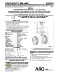
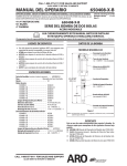
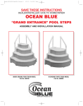
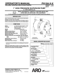
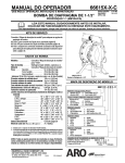
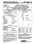
613100-1
OPERATOR’S MANUAL
613104
INCLUDING: OPERATION, INSTALLATION & MAINTENANCE
ALSO INCLUDE MANUALS: 6544X-X AIR MOTOR (97999-64), 641523 CONTROL HANDLE (97999-230),
S-633 GENERAL INFORMATION MANUAL (PN 97999-625)
4-1/4” AIR MOTOR
10:1 RATIO
4” STROKE
613100 -1
WASH PUMP
613104
DETERGENT PUMP ASSEMBLY
RELEASED:
REVISED:
(REV. N)
4-10-67
8-26-10
READ THIS MANUAL CAREFULLY BEFORE INSTALLING,
OPERATING OR SERVICING THIS EQUIPMENT.
It is the responsibility of the employer to place this information in the hands of the operator. Keep for future reference.
A
SERVICE KITS
• Use only genuine AROR replacement parts to assure compatible
pressure rating and longest service life.
• 637001 for repair of 61371-1 Lower Pump end.
• 61268 for repair of 65444-B Air Motor section.
• 637033 for repair of 641523 Control Handle.
65444-B AIR MOTOR
See Operators Manual
Oil Daily
GEAR OIL
WITH SAE 90W
SPECIFICATIONS
Model . . . . . . . . . . . . . . . . . . .
Type . . . . . . . . . . . . . . . . . . . .
Ratio . . . . . . . . . . . . . . . . . . . .
Air Motor Diameter . . . . . . . . .
Stroke (Double Acting) . . . . .
Air Inlet . . . . . . . . . . . . . . . . .
Air Exhaust . . . . . . . . . . . . . .
Material Outlet . . . . . . . . . . . . .
Material Inlet . . . . . . . . . . . . . .
Pump Construction . . . . . . .
Dimensional Data . . . . . . . . . .
613100-1
Air Operated, Wash Pump
10:1
4-1/4” (10.795 cm)
4” (10.16 cm)
1/2 - 14 NPTF - 1 (f)
1-1/4 - 11-1/2 NPTF - 1 (f)
3/8 - 18 NPTF - 1 (f)
Barbed
Series 425 Stainless Steel
See Figure 1
Air Inlet Pressure Range . . . . .
Fluid Pressure Range . . . . . . .
Displacement In3 Per Cycle . . .
Cycles Per Gallon . . . . . . . . . .
Maximum Delivery / Min. . . . . .
Accessories Available: . . . . . .
0 - 150 p.s.i. (0 - 10.3 bar)
0 - 1500 p.s.i. (0 - 103 bar)
11.0 (.18 L)
21 (5.5 L)
3.9 Gallons (14.8 L)
61113 Wall Mount Bracket
61371-1LOWER
PUMP END
E
F
INGERSOLL RAND COMPANY
209 NORTH MAIN STREET -- BRYAN, OHIO 43506
www.ingersollrandproducts.com
E2010
H
K
P
N
Q
R
L
FIGURE 1
M
ITEM DESCRIPTION
The Aro model 613100-1 and 613104 wash pump has been designed for
heavy duty cleaning with detergents, caustics, and dilute acid type cleaners. (The model 613100-1 basic pumps come without accessories).
The 10:1 ratio double acting pump section is separated from the air motor to prevent any cleaning solution from coming in contact with and
damaging the air motor.
All metal parts in the pumping section are manufactured from 316 stainless steel or “K” monel, the packing and “O” rings are manufactured from
Nitrile, and the packing back-ups and portions of the material piston are
manufactured from acetal resins.
Packings, “O” rings, and material pistons of virgin PTFE and packing
back-ups of glass filled PTFE are available on special request.
The 4-1/4 inch air motor is of the double acting reciprocating type. The
valving in the air motor uses “D” type valves and is mechanical with a
pneumatic assist.
The 613104 wash pump may be directly mounted in the two inch bung of
a standard 55 gal. drum or, when using the 61113 mounting bracket, the
pump can be mounted on the wall or in a 55 gal. open head drum. (The
61139 suction tube comes with a 100 mesh screen).
(800) 495--0276 D FAX (800) 892--6276
J
G
PERFORMANCE
GENERAL DESCRIPTION
B
CCN 99711491
A
B
E
F
G
H
J
K
Nipple
Airline Lubricator
Pump Bracket Assembly (2” Bung)
Hose Assembly (3/8 I.D. 2 Fabric)
Control Handle Assembly
Suction Tube Assembly (Includes J, K, L & M)
Hose Clamp
Tube
PART NO.
Y27-4-N
L36341-110
61113
622427-40
641523
61139-1
61204-1
92249-26
L Hose Clamp
76315
M Screen Assembly
61138
N Bent Pipe Assembly (Includes P, Q & R)
61133
P Bent Pipe
76821
Q Nozzle Cover
76330
R Spray Tip
TP6250-18
OPERATING PRECAUTIONS
WARNING HAZARDOUS PRESSURE. Do not exceed maximum operating pressure of 1500 p.s.i. (103 bar) at 150 p.s.i.
(10.3 bar) inlet air pressure.
PUMP RATIO X
INLET PRESSURE TO PUMP MOTOR
=
MAXIMUM PUMP
FLUID PRESSURE
Pump ratio is an expression of the relationship between the pump motor area and the
lower pump end area. EXAMPLE: When 150 p.s.i. (10.3 bar) inlet pressure is supplied
to the motor of a 10:1 ratio pump it will develop a maximum of 1500 p.s.i. (103 bar) fluid
pressure (at no flow) - as the fluid control is opened, the flow rate will increase as the
motor cycle rate increases to keep up with the demand.
WARNING Refer to general information sheet for additional
safety precautions and important information.
OPERATING INSTRUCTIONS
1. Fill air line lubricator bowl with SAE 90 gear oil.
2. Oil the lower pump assembly section by squirting SAE 90 Gear Oil
into the two holes marked “Oil Daily”.
3. Fill the cleaning solution container with clear water.
4. Connect the air supply line to the air line lubricator.
5. Open the (G) control handle assembly by squeezing the trigger until
water sprays out the spray tip.
6. Adjust air line oiler to approximately 1 drop every 2 minutes by turning adjusting screw clockwise for less flow.
7. Close control handle.
8. Add the proper amount of cleaning solution to cleaning solution container. Insert the (N) bent pipe assembly into the cleaning solution
and open the control handle assembly. Continue holding the control
handle open until spray from the (N) bent pipe assembly has thoroughly mixed the cleaning solution.
NOTE:
• Most cleaning solutions will perform more efficiently in warm water.
• Powdered detergents will be easier to mix if they are dissolved in
a container of hot water first.
• Consult chemical manufacturer’s recommendations for proper
mixing and concentration
9. The air supply line should be disconnected when the wash pump assembly is not in operation.
CAUTION: DO NOT ALLOW THE AIR MOTOR TO RUN AFTER THE
SOLUTION CONTAINER IS EMPTIED.
CLEANING INSTRUCTIONS
Use the cleaning instructions supplied by the cleaning chemical supplier.
General cleaning instructions for detergents and caustics: (In the event
cleaning instructions are not supplied by chemical supplier).
1. Lightly and rapidly cleaning solution to object being cleaned.
2. Let cleaning solution stand on the object for two or three minutes.
3. Starting from the bottom up, clean the object with cleaning solution
holding the spray tip 6 to 8 inches away from object and at approximately 45_. The 45_ angle will produce a chiseling effect for better
cleaning.
4. Rinse the object thoroughly with clean water from the top down.
General cleaning instructions for aluminum brightening: (If not supplied
by chemical supplier).
1. Apply aluminum brightener to an area of approximately 100 square
feet (approximately 3 semi-trailer panels) from the bottom up.
2. Let the brightening solution soak until light foaming occurs on the
aluminum.
3. Rinse thoroughly with clear clean water from the top down.
CAUTION: Brightening solution will etch glass and will burn aluminum if permitted to soak after the light foaming occurs.
PAGE 2 OF 6
PUMP PERFORMANCE CHART
Operating
Air Pressure
(PSIG)
50
75
100
125
150
Spray Tip
Orifice
Pump Back
Pressure
(PSIG)
Air
Usage
(CFM)
Pump
Speed
(CPM)
Flow
Rate
(GPM)
.042
.052
.062
.042
.052
.062
.042
.052
.062
.042
.052
.062
.042
.052
.062
410
370
330
640
600
500
880
800
720
1080
1000
920
1300
1200
1100
5.66
6.62
10.35
8.75
12.96
19.85
13.34
19.78
28.80
20.00
26.50
40.00
25.50
34.32
50.60
20
24
35
23
32
47
27
37
56
31
42
63
34
47
68
.94
1.16
1.72
1.09
1.53
2.25
1.25
1.81
2.68
1.44
2.00
3.00
1.59
2.19
3.25
PSIG = Pound per square inch gage
CPM = Cycles per minute
CFM = Cubic Feet per minute
GPM = Gallons per minute
NOTE: Pump should not be operated continuously at speeds in excess
of 60 cycles per minute.
MAINTENANCE
The basic pump consists of two major components: 1. Air Motor, 2. Lower Pump End. The air motor is connected to the lower pump end by a
spacer tube - this allows access for lubricating the upper packing gland
in the lower pump end, and to prevent air motor contamination because
of normal wear and eventual leakage through material packing gland.
The air motor is removable and is to be serviced separately. Refer to air
motor manual for service and parts.
• Periodically flush entire pump system with a solvent that is compatible with the material being pump.
• Periodically inspect and replace if necessary the (M) screen assembly on the bottom of the (H) suction tube assembly.
• Refer to Disassembly Procedures of air motor and lower pump end
(see Page 3 and 4) for correct breakdown.
• Disassembly should be done on a clean work bench with clean
cloths to keep parts clean.
• If replacement parts are necessary, consult drawing containing
parts for identification.
• Before assembling, lubricate parts where required. When assembling “O” rings or parts adjacent to “O” rings, care must be exercised
to prevent damage to “O” rings and “O” ring groove surfaces.
Daily Maintenance
1. The airline lubricator should be filled with SAE 90 weight gear oil.
2. Maintain the oil level on the packings in the lower pump assembly.
Use SAE 90 weight gear oil.
3. The air line should be disconnected from the air motor if the pump
sits idle for long periods.
613100-X
INSTALLATION
(See Figure 1)
1. Attach the (E) pump bracket assembly to the lip of the drum and
tighten the retaining screw or bolt the pump bracket assembly to the
wall using the 3 holes provided in the back of the (E) pump bracket
assembly.
2. Attach the (H) suction tube assembly to the barbs on the bottom of
the pump assembly and tighten the (J) hose clamp.
NOTE: Soak (K) tube in hot water for ease of installation over barbs.
3. Place the (H) suction tube assembly and the lower pump assembly
through the 2” NPT bung in the pump mounting bracket. Thread the
lower pump assembly into the pump mounting bracket, align the material outlet in the direction the (F) material hose should go, and tighten the (8) lower lock nut. (See Figure 4). Loosen (1) upper lock nut,
(Figure 4), and turn the air inlet of the 65444-B air motor in the direction desired and retighten the (1) upper lock nut.
4. Attach the (A) nipple and (B) airline lubricator.
5. Attach the (F) hose assembly to the 3/8 NPT thread in the material
outlet of the pump.
6. Attach the (F) hose assembly to the 3/8 NPT thread in the (G) control
handle assembly.
7. Attach the 1/4 NPT thread of the (N) bent pipe assembly to the outlet
of the (G) control handle assembly.
CAUTION: DO NOT CONNECT THE AIR AT THIS TIME.
NOTE: Apply a thread sealer or PTFE tape to all pipe threads.
PUMP SERVICE PROCEDURES
PUMP DISASSEMBLY
To disassemble the lower pump assembly from the 65444-B air motor
assembly:
1. Clamp the air motor assembly in a vise as shown in Figure 2.
2. Looses the 90606 lock nut.
3. Place strap wrench around the 76048 spacer tube and remove by
turning counter clockwise. If the strap wrench slips on the 76048
spacer tube, wrap a piece of 400 sand paper around the 76048
spacer tube and under the strap wrench. (NOTE: Pipe wrench will
damage the finish of the tube).
4. After the 76048 spacer tube has been unscrewed from the 65444 air
motor assembly, pull the lower pump assembly down until the (3)
plunger is exposed.
5. Place a 1-3/16 open end wrench or an adjustable wrench on the flats
of the (3) plunger and a 1-1/8 wrench on the 90609 retaining screw
as shown in Figure 3.
90606 LOCKNUT
76048
SPACER TUBE
LARGE BOSS
FIGURE 2
CAUTION: Extreme caution should be used when disassembling
the (3) plunger to prevent scoring the plunger. Do not use a pipe
wrench or pliers on the plunger.
6. Set the lower pump end aside.
7. Remove the 76748 gasket from the 65444-B air motor assembly.
PUMP REASSEMBLY
1. Insert the 76748 gasket into the air motor base.
2. Clean threads, apply Loctite #242 to the threads of the 90609 retaining screw and screw them securely into the (3) plunger. See Figure
3.
3. Apply PTFE tape or Parker Ferulube to the threads on the (2) spacer
tube and screw it into the 65775 air motor base and insert assembly.
4. Tighten the (1) lock nut.
76748 GASKET
90595 ROD
90609 RETAINING SCREW
APPLY
LOCTITE #242
SPECIAL TOOLS AVAILABLE
• 21946T used to install 76947 Packing Screw in 641529 and 641523
Control Handles.
• 90350 Inserting Tool. Allows a positive seating to guide Ring and
Adapter in Air Motor.
• 640081-B Aro Strap Wrench.
• 38237 Spanner Wrench. Tightens Seat in Lower Wash Pump.
• 37437-1 Loctite 271 Liquid Lock.
65775 AIR MOTOR BASE
& INSERT ASS’Y
90608 SHOULDER NUT
(3) PLUNGER
(2) SPACER TUBE
(1) LOCK NUT
FIGURE 3
613100-X
PAGE 3 OF 6
LOWER PUMP SERVICE PROCEDURES
LOWER PUMP DISASSEMBLY
LOWER PUMP END REASSEMBLY
NOTE: All threads are right hand.
1. Clamp the lower pump assembly in a vise side ways on the (7) pump
body with the material outlet up.
2. With a plastic hammer tap all around the lower end of the (16) suction tube. (Close to the bottom).
3. Place strap wrench around the (16) suction tube and hold securely.
Place a wrench on the foot valve body and disassemble from the
suction tube.
4. Remove the (17) dowel pin and (20) ball from the (21) foot valve
body.
5. Remove the (19) “O” ring from (21) foot valve body.
6. Disassemble the (16) suction tube from the pump body.
7. Remove the (3) plunger using extreme caution not to damage the
finish on the O.D.
8. Remove the (9) “O” ring from the (7) pump body.
9. Place the strap wrench on the (2) spacer tube and unscrew the
spacer tube from the (7) pump body.
10. Place a wooden dowel or hammer handle in the (2) spacer tube and
lightly tap the (4) washer, and the (5) packing out of the chamber.
11. Remove the (6) gasket from the (7) pump body.
12. Clamp the flats of the (11) rod in the vise. Remove the (3) plunger
and the (10) lock washer from the (11) rod.
13. Remove the (15) nut.
14. With a spanner wrench remove the (14) retaining nut.
15. Remove the (12) cup and (13) “O” ring.
NOTE: Use anti seizing compound on all stainless steel threads.
1. Thoroughly grease and install the (4) washer, and the (5) packing
into the bore of the (2) spacer tube with the lips toward the opening.
2. Seat the (6) gasket in the (7) pump body.
3. Apply PTFE tape or Parker Ferulube to the threads on the end of the
(2) spacer tube that the packing was installed into, and insert into the
top of the (7) pump body (top does not have external threads) and
screw securely together.
4. Thoroughly grease and install the (9) “O” ring into the bottom of the
pump body.
5. Place the (3) plunger (with 1/2 - 20 thread down) into the top of the
(2) spacer tube, and slowly work the plunger through the (5) packing, until the plunger extends out of the (7) pump body.
6. Place the (10) lock washer over the threads on the (11) rod.
7. Clean the threads of both pieces with solvent, apply Loctite and
screw securely onto the (3) plunger.
8. Slide the assembled (12) cup and (13) “O” ring onto the (11) rod.
9. Thoroughly clean with solvent and apply Loctite to the 7/16 - 20
threads of the (11) rod.
10. Screw the (14) retaining nut onto the (11) rod and tighten with a
spanner wrench.
11. Screw the (15) nut onto the (11) rod and tighten.
12. Push the assembled (3) plunger and (12) cup up until the cup comes
in contact with the (7) pump body.
13. Thoroughly grease the inside of, and apply PTFE tape or Parker
Ferulube to the external threads of the (16) suction tube. Carefully
force the externally threaded end of the suction tube over the (13)
“O” ring and screw into the (7) body.
14. Thoroughly grease and install the (19) “O” ring on the (21) foot valve
body.
15. Place the (20) ball in the (21) foot valve body and insert the (17) dowel pin into the two holes in the foot valve body.
16. Apply PTFE tape or anti-seizing to the threads of the (21) foot valve
body and screw them into the (16) suction tube and tighten securely.
17. The lower pump end is now assembled.
PAGE 4 OF 6
613100-X
LOWER PUMP END PARTS LIST
ITEM
DESCRIPTION
Qty
Z SERVICE KIT PARTS
1
2
3
Z4
Z5
Z6
7
8
637001
1
1
1
1
1
1
1
1
90606
76048
90615
77398
77744
76748
65793-2
76248
1
77361
10 Lockwasher (1/2”)
1
Y14-816-T
11 Rod
1
76045
1
1
77265
Y325-325
1
76046
1
1
1
1
Y11-7-T
90621
90620
Y325-224
1
1
1
90948
76932
Y45-308-T
Z
Locknut
Spacer Tube
Plunger
Washer
Packing
Gasket
Pump Body
Locknut
Part No.
9 “O” Ring (2.129” o.d.)
12 Cup
Z 13 “O” Ring (3/16” x 1-7/8” o.d.)
Z
14 Retaining Nut
15
16
17
Z 19
Nut (7/16” - 20)
Suction Tube
Dowel Pin
“O” Ring (1/8” x 2” o.d.)
20 Ball
21 Foot Valve
22 Adapter (3/4 NPT x 3/8 NPT)
1
2
2-1/8 - 16 UN-2A TH’D
3
4
5
6
7
3/8” NPTF
Material Outlet
8
9
10
11
2” NPSM TH’D
22
12
13
14
Clean with solvent
and apply Loctite 271
15
2” - 16 UN-2B TH’D
16
17
19
FIGURE 4
20
21
Use Loctite Nickel Anti-Seize on All Threads.
Use Tricresyl Phosphate (Wet-Sol “Plus”) only
to Lubricate Packings when Assembling Pump.
613100-X
PAGE 5 OF 6
TROUBLE SHOOTING
No material (stalled pump).
• Obstructed (R) spray tip. Remove spray tip and clean.
• Obstructed (F) hose assembly. Remove control handle and operate
pump until line is clear.
• Obstructed (G) control handle assembly. Disassemble and clean.
No material (Pump continually cycles).
• Empty material supply. Disconnect the air. Replenish material supply. Connect the air. Open (G) control handle assembly until pump is
primed.
• 90609 Retaining screw (See Figure 3) disassembled from (3) plunger. (Figure 4). Connect the retaining screw to the plunger. (Follow
instructions for assembly of air motor to lower pump end).
• Damaged (H) lower suction tube. Replace suction tube.
• Loose (J) hose clamp assembly on (K) tube. Tighten clamp.
Material on One Stroke only (Fast Downstroke).
• (20) Ball in (21) foot valve not seating, or damaged (19) “O” Ring.
Remove the foot valve. Remove the ball from the foot valve. Clean
and inspect ball and foot valve. If either ball or foot valve is damaged,
replace, also replace (19) “O” Ring if damaged. (See Lower Pump
End Instructions).
Material on One Stroke only (Fast Upstroke).
• Worn (13) “O” Ring. Replace with new (13) “O” Ring. (See Lower
Pump End Instructions).
Material Leakage Out the Oil Daily Holes in Pump.
• Worn (5) packing. Replace worn packing. (See Lower Pump End Instructions).
Air leakage out of the Main Exhaust.
• Worn 90796 valve insert. Replace the valve insert. (See Air Motor
Instructions).
• Loose 65027 Piston Assembly. Tighten piston assembly. (See Air
Motor Instructions).
• Damaged 65027 Piston Assembly. Replace piston assembly. (See
Air Motor Instructions).
• Warped or worn 65028 valve plate and pin assembly. Replace valve
plate and pin assembly.
Continual leakage out of the bleeder hole in the Head Assembly.
• Worn 91207 “O” Ring or 91007 Seal. Replace the “O” Ring and Seal.
(See Air Motor Instructions).
Air leakage out of the bleeder hole on the Air Motor Assembly
downstroke.
• Worn Y186-51 “U” cup. Replace the “U” cup. (See Air Motor Disassembly Instructions).
Air leakage out of the Oil Daily Holes in the Pump Section.
• Worn Y325-210 “O” Ring. Replace the “O” Ring. (See Air Motor Instructions).
Material leakage around the Control Handle.
• Loose 76947 gland. Tighten packing screw. (See Control Handle Instructions).
• Worn 77516 packings. Replace packings. (See Control Handle Instructions).
OPTIONAL ACCESSORIES
640081-B STRAP WRENCH
61113 MOUNTING BRACKET
FIGURE 5
PN 97999-92
PAGE 6 OF 6
613100-X