1
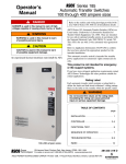
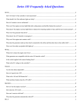
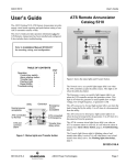
Series 165 Automatic Transfer Switches
Owner’s
Manual
rated 100, 200, & 230 amps, single phase, 240 V ac
for automatic 2–wire start generators
DANGER is used in this manual
to warn of risk of electrical shock
from high voltages capable of
causing shock, burns, or death.
!
ASCO Series 165 Automatic Transfer Switches are Listed
under the Underwriter’s Laboratories Standard for Transfer
Switch Equipment, UL–1008. They are intended for use
only in optional standby systems in accordance with the
National Electrical Code, NEC/NFPA 70, Article 702. This
ATS is for use with 2–wire automatic start generators only.
Refer to Application Information 381339–219 to confirm
that you have selected the appropriate product for the
intended installation.
WARNING is used in this
manual to warn of possible
personal injury.
Rating Label
Each Automatic Transfer Switch (ATS) has rating labels to
define the loads and fault current withstand/ closing ratings.
Refer to those label on the Transfer Switch for specific values.
!
CAUTION is used in this manual to warn
of possible equipment damage.
Installation should be performed by a licensed electrician
and in accordance with the National Electrical Code (NEC)
and all local electrical code requirements. Read and
understand all instructions before installing, servicing, or
operating. Failure to do so could result in serious
personal injuries or property damage.
!
INJURY or SWITCH DAMAGE
Do not exceed the rating label
values; it can cause personal injury or serious switch damage.
Series
165
Nameplate
The Transfer Switch
nameplate includes data
for each specific ASCO
Series 165 ATS. Use the
switch only within the
limits shown on this
nameplate. A typical
Catalog Number is also
shown below with its
elements explained:
Automatic Transfer Switch
for use on Standby Systems
Cat No 165A2200F3C
Ser No 123456
200 A BOM 999999
240 V 60 Hz
Catalog number
product
designation
165
A
2
200
F
3
neutral
A = solid neutral
enclosure
C = Type 1
F = Type 3R
control group code
3 = automatic
poles
2 = 2 lines
voltage code
F = 240 V AC
ampere rating
100, 200, or 230 amps
50 Hanover Road, Florham Park, New Jersey 07932–1591 USA
1 800 937–2726 (ASCO), for service call 1 800 800–2726 (ASCO) www.asco.com
C
381333–163 C
ASCO POWER TECHNOLOGIES CANADA PO Box 1238, 17 Airport Road, Brantford, Ontario, Canada N3T 5T3
telephone 519 758–8450, fax 519 758–0876, for service call 1 888 234–2726 (ASCO) www.asco.ca
TABLE OF CONTENTS
Specifications . . . . . . . . . . . . . . . . . . . . . . . . . . . . . . . . . . . . . 3
Introduction . . . . . . . . . . . . . . . . . . . . . . . . . . . . . . . . . . . . . . 3
Installation . . . . . . . . . . . . . . . . . . . . . . . . . . . . . . . . . . . . . . . 4
Indicator Lights . . . . . . . . . . . . . . . . . . . . . . . . . . . . . . . . . . . 6
Push Buttons . . . . . . . . . . . . . . . . . . . . . . . . . . . . . . . . . . . . . 6
Utility Failure . . . . . . . . . . . . . . . . . . . . . . . . . . . . . . . . . . . . . . 6
Electrical Line Connections . . . . . . . . . . . . . . . . . . . . . . . . . 4
Cable Spacers (200 amp. unit) . . . . . . . . . . . . . . . . . . . . . . 4
Automatic Generator Exerciser . . . . . . . . . . . . . . . . . . . . . . 7
Manual Generator Testing . . . . . . . . . . . . . . . . . . . . . . . . . . 7
Cable Connections . . . . . . . . . . . . . . . . . . . . . . . . . . . . . . . . 4
Generator Starting Contacts . . . . . . . . . . . . . . . . . . . . . . . . 4
Generator Test with Load Transfer . . . . . . . . . . . . . . . . . . . 7
Generator Test without Load Transfer . . . . . . . . . . . . . . . . 7
Functional Test (after installation) . . . . . . . . . . . . . . . . . . . . 5
Operation . . . . . . . . . . . . . . . . . . . . . . . . . . . . . . . . . . . . . . . . 6
Troubleshooting . . . . . . . . . . . . . . . . . . . . . . . . . . . . . . . . . . . 8
load power
connections
alternate source
(generator)
power
connections
digital controller
with control display
neutral
terminal
cable spacers
maintenance
handle next to
wheel weight
(see DANGER
under Manual
Operation)
ground
terminal
preferred
source
(utility) power
connections
transfer switch
Series 165 Automatic Transfer Switch in Type 1 enclosure (cover removed)
2
SPECIFICATIONS
ENCLOSED AUTOMATIC TRANSFER SWITCH
CONTROLLER
Enclosure Size
Type 1 . . . . . . . . . . . . . . . . . . 24” H x 14¼” W x 8” D
(610 mm H x 362 mm W x 203 mm D)
Type 3R . . . . . . . . . . . . . . . 25” H x 14¾” W x 8½” D
(635 mm H x 375 mm W x 216 mm D)
Voltage (nominal) . . . . . . . . . . . . . . . . . . . . . . 220–240 V ac
Pickup (source acceptable) . . . . . . . . . . . . 204 V ac
Dropout (source unacceptable) . . . . . . . . 180 V ac
Weight
Type 1 enclosure . . . . . . . . . . . . . . . . . . . . . . 67 lb
Type 3R enclosure . . . . . . . . . . . . . . . . . . . . . 82 lb
Temperature
Operating . . . –4˚ F to +122˚ F(–20˚ C to +50˚ C)
Storage . . . . –67˚ F to +149˚ F(–55˚ C to +65˚ C)
TRANSFER SWITCH
Poles . . . . . . . . . . . . . . . . . . . . . . . . . . . . . . . . . . . . . . . . . . . . 2
Voltage (nominal) . . . . . . . . . . 220–240 V ac single phase
Frequency (nominal) . . . . . . . . . . . . . . . . . . . . . . . . . . . 60 Hz
Current (depending upon the unit) 100, 200, or 230 amps
Withstand / Close–On Current . . . . . . . . . . . . 10,000 amps
RMS Symmetrical amps 240 V ac max.
for any circuit breaker, manufacturer, or Type
per National Electrical Code, NEC/NFPA 70
100 amp. Transfer Switch power terminals accept wire sizes
one #14 to 4/0 AWG AL or CU
200 amp. Transfer Switch power terminals accept wire sizes
one #14 to 4/0 AWG CU (copper only)
230 amp. Transfer Switch power terminals accept wire sizes
one #14 to 4/0 AWG CU (copper only)
Frequency (nominal) alternate (generator) source . 60 Hz
Pickup (source acceptable) . . . . . . . . . . . . . . . 57 Hz
Dropout (source unacceptable) . . . . . . . . . . . 54 Hz
Generator control contacts
Start / Stop spdt 5 A max / 300 mA min at 30 V dc max.
terminals accept #22 to #14 AWG
stranded copper wire per terminal
Time Delays
Ignore preferred (utility) source outages . . . . . . . . 3 sec.
Ignore alternate (generator) source outages . . . . 15 sec.
Load transfer to alternate (generator) source . . . 15 sec.
Load retransfer to preferred (utility) source . . . . . . 5 min.
Generator cooldown period (after load retransfer) 1 min.
Automatic Generator Exerciser
Repeat time . . . . . . . . . . . . . . . . . . . . . . every 14 days
Duration . . . . . . . . . . . . . . . . . . . . . . . . . . . 20 minutes
INTRODUCTION
INTRODUCTION
ASCO Series 165 Automatic Transfer Switches are Listed
under the Underwriter’s Laboratories Standard for Transfer
Switch Equipment, UL–1008. They are intended for use only
in optional standby systems in accordance with the National
Electrical Code, NEC/NFPA 70, Article 702.
This automatic transfer switch is intended for standby power
applications in residential or light commercial use only.
!
The Series 165 Automatic Transfer
Switch is not for emergency or
life–support systems.
This product is not intended for emergency or
life–support systems.
If you have more stringent application requirements contact
ASCO for other products suitable for critical applications.
The automatic transfer switch helps provide safe
connection of the alternate source (generator) to the
electrical load after disconnecting the preferred source
(utility). It contains a double–throw, electromechanical
switching device for inherent isolation of the preferred and
alternate sources. This isolation prevents the danger of
connecting the utility to the generator which could cause
damage or personal injury. The automatic transfer switch’s
digital controller provides continuous monitoring of both
power sources and a start/stop signal to the generator.
3
INSTALLATION
Installation of the ASCO Series 165 automatic transfer
switch must be performed by a licensed electrician. It must
be installed according to the National Electrical Code and
all local electrical code requirements. Refer to the
installation drawing and wiring diagram.
!
Remove the enclosure cover and inspect the unit for ship–
ping damage. If damage is evident do not install the unit. Type
1 enclosure is for indoor use only (refer to local codes for Type
4 use). Mount the automatic transfer switch vertically to a rigid
supporting structure. Level all mounting points with flat
washers behind the holes to avoid distortion of enclosure.
ELECTRICAL LINE CONNECTIONS
Installation wiring must be performed by a licensed
electrician in accordance with the National Electrical Code
(NEC) and all local electrical code requirements.
The automatic transfer switch must be protected by suitably
sized circuit breakers feeding the preferred and alternate
source terminals. The ratings of the circuit breakers must be
based on the requirements of the National Electrical Code
for its nameplate ampere and short circuit withstand ratings.
See the wiring diagram provided with the unit.
ELECTROCUTION HAZARD
Turn off utility power and turn off the
generator to prevent electrocution
when wiring the transfer switch.
CABLE SPACERS (200 and 230 amp. units)
Three cable spacers are included with 200 and 230 ampere
size transfer switches. Run the power cables through the
cable spacers as shown here and position the cable
spacers approximately 1½ inches from the terminal lugs.
Use copper cables for 200 and 230 amp. transfer switches.
L3 L7
L6
alternate source (generator)
200 & 230 amp. transfer
switches require cable
spacers and copper cables
L1
4
Prepare the wires for connection as follows: strip the
insulation; avoid nicking or ringing the conductors when
stripping the cable. Remove surface oxides from
conductors by cleaning with a wire brush. Apply electrical
joint compound and wipe away excess. Insert prepared
cable into lug and tighten the lug to the torque specified on
the rating label on the transfer switch.
Connect the preferred source (utility) line 1 and 2 wires to
the terminal lugs marked L1 and L5 at the bottom. Connect
the alternate source (generator) line 1 and 2 wires to the
terminal lugs marked L2 and L6 at the upper middle.
Connect the load line 1 and 2 wires to the terminal lugs
marked L3 and L7 at the top of the transfer switch. Neutral
and ground terminals are provided.
GENERATOR STARTING CONTACTS
Before wiring the generator starting contacts refer to the
generator manufacturer’s installation manual for requirements. Make all connections to the controller with the generator battery disconnected. Verify that the ignition switch
is in the OFF position. Connect the generator starting contacts to the appropriate terminals on terminal block TB7 on
the Controller (CP). See the wiring diagram provided with
the unit.
For wiring convenience terminal block TB7 has a removable
plug. Reconnect the plug with terminal screws facing inward.
!
CONTROLLER DAMAGE. Observe polarity when
connecting the generator battery to the controller.
Refer to wiring diagram. Be sure to reinstall the
TB7 block with terminal screws facing inward.
cable spacers
1 ½ inch approximate
from terminal lugs
L2
CABLE LOOSENING DUE TO SHORT–CIRCUIT. Install
3 cable spacers 1½ in. from terminal lugs to prevent
cables from loosening in a short–circuit condition.
CABLE CONNECTIONS (see wiring diagram)
MALFUNCTION or SHORTENED LIFE
Protect the unit from construction grit and metal
chips to prevent malfunction or shortened life.
load
!
cable spacer
L5
preferred source (utility)
removable
terminal
block TB7
Be sure to
reinstall
with
terminal
screws
facing
inward.
digital
controller
FUNCTIONAL TEST (after installation)
After installing the Series 165 automatic transfer switch
perform the following three–part functional test.
source acceptable lights
1 – MANUAL OPERATION
ELECTROCUTION – FLASH HAZARD
Do not manually operate the transfer
switch until utility and generator are
disconnected; open circuit breakers.
test button
1. Put both the preferred source circuit breaker and the
alternate source circuit breaker feeding the automatic
transfer switch in the OFF position. Verify that ALL
POWER IS OFF ! (See page 2 for handle location.)
2. Grasp the maintenance handle and turn it quickly with
your thumb and fingers to manually operate the transfer
switch. The switch should operate smoothly without
binding. If it does not, check for shipping damage or
construction debris.
transfer switch on utility
(preferred source) light
maintenance handle
With ALL POWER OFF
grasp maintenance
handle and turn it
quickly with your
thumb and fingers.
weight marked P (preferred) and A (alternate)
3. After checking the manual operation operate the handle
again quickly to return the transfer switch to the preferred
position (letter P on the round weight facing you).
2 – VOLTAGE CHECKS
The Series 165 automatic transfer switch is rated for
nominal 240 V ac at 60 Hz (as stated on the nameplate).
Verify that both your preferred and alternate sources are
also 240 V ac nominal, 60 Hz. See the wiring diagram.
3 – ELECTRICAL OPERATION
This procedure checks the electrical operation of the
automatic transfer switch. If the actual operation does not
follow this procedure, consult the Troubleshooting section.
!
PERSONAL INJURY HAZARD
Install front cover before operation.
An electrical system fault could
cause a flash and cause injury.
transfer switch on generator
(alternate source) light
3.
Turn on the preferred source (utility) circuit breaker.
4.
Turn on the alternate source (generator) circuit breaker.
5.
Verify that UTILITY (preferred source) acceptable light is on.
6. Verify that the TRANSFER SWITCH on utility (preferred
source) light is on.
7. This step will start the generator. Press and hold the
Push to Test button until the GENERATOR (alternate
source) acceptable light comes on and stays on. Then
release the button.
This light indicates that the generator is running and
that its output voltage and frequency are acceptable.
Under typical conditions, the light should come on after
about 5 to 10 seconds. If the generator is running and
fails to produce the proper voltage and frequency after
60 seconds then a malfunction has occurred (consult
the Troubleshooting section).
8. About 15 seconds after the GENERATOR (alternate
source) acceptable light comes on, the automatic
transfer switch transfers the load from the utility to the
generator. The TRANSFER SWITCH on generator
(alternate source) light comes on.
9. The transfer switch stays connected to the generator for
5 minutes. Then the load is transferred back to the utility.
To bypass time delay, press and release the Push to Test
button again.
1. Install the enclosure cover and tighten the screws.
10. After load retransfer to utility, the generator runs 1 minute
(without load), then shuts down. The GENERATOR
acceptable light goes off indicating that generator is off.
2.
This completes the Functional Test. Proceed to next page.
Verify that the generator battery is connected and that the
generator’s starting controls are set for automatic.
5
OPERATION
utility (preferred source)
acceptable light
generator (alternate source)
acceptable light
PUSH BUTTONS
On the front control display are two push buttons that
control the operation of the generator and the automatic
transfer switch.
● Push to Test (button on the left side)
exerciser
light
● This button is used to test the system. See the Manual
Generator Testing section on the next page.
● This button can be used to cancel any active time delay.
Press and release the button to bypass the time delay.
● This button can be used to clear displayed error codes.
See Troubleshooting section, Problem 8.
● Automatic Generator Exerciser (right button)
● This button is used to set the automatic generator
exerciser. See the next page.
transfer switch on utility transfer switch on generator
(alternate source) light
(preferred source) light
INDICATOR LIGHTS
On the front control display are five lights that indicate the
status of the sources and the automatic transfer switch.
❍ Utility (preferred source) acceptable
(light at the top left of the display)
● When on, this light indicates that the utility voltage is
acceptable for connection to the load.
❍ Generator (alternate source) acceptable
(light at the top right of the display)
● When on, this light indicates that the generator voltage
and frequency are acceptable for connection to the load.
❍ Transfer Switch on utility (preferred source)
(light at the center left of display)
● When on, this light indicates that the load is connected to
the utility (preferred source).
❍ Transfer Switch on generator (alt. source)
(light at the center right of display)
● When on, this light indicates that the load is connected to
the generator (alternate source).
❍ Automatic Generator Exerciser
(light above button at the right of display)
● When the utility is acceptable and the load is on the utility,
this light flashes the number of days until the next exercise
period. When it is off, no exerciser period is set. The light is
also off any time the generator is running.
6
UTILITY FAILURE
The load is normally connected to the preferred source
(utility) if that source is acceptable. If the preferred source
(utility) fails, the following sequence occurs:
1. The UTILITY source acceptable light goes off.
2. The automatic transfer switch waits three seconds to prevent nuisance starting of the generator from momentary
dips of the utility voltage. If the utility is restored during the
three seconds, the UTILITY source acceptable light
comes on and no further action is taken.
3. If the utility remains unacceptable for three seconds, the
automatic transfer switch cranks and starts the generator.
4. Once the generator starts, the automatic transfer switch
waits until the generator voltage and frequency are
acceptable. Then the GENERATOR source acceptable
light comes on.
5.
When the generator is acceptable, the automatic transfer
switch waits 15 seconds to allow the generator to warm up.
Then it transfers the load to the generator. The TRANSFER
SWITCH on generator (alternate source) light comes on.
6. The automatic transfer switch waits for the utility source to
be restored. When the utility again becomes acceptable
the UTILITY source acceptable light comes on.
7. The automatic transfer switch then waits 5 minutes to
allow the utility to stabilize. Then it retransfers the load
back to the utility. The TRANSFER SWITCH on utility
(preferred source) light comes on.
8. After load retransfer the generator will continue to run
unloaded for one minute for engine cooldown. Then it is
stopped. The GENERATOR acceptable light goes off.
AUTOMATIC GENERATOR EXERCISER
automatic generator exerciser light
The automatic generator exerciser automatically exercises
the generator for 20 minutes once every 14 days.
TO SET EXERCISER
Press and release the Automatic Generator Exerciser button. After about 8 seconds the exerciser light flashes 14 times
to indicate that the exerciser has been set. The number of
flashes indicates the number of days until the next exercise period (at approximately the same time the button was pressed).
TO DISABLE EXERCISER
Press and hold the Automatic Generator Exerciser button
until the light above the button goes off (light flashes then
goes off). The exerciser is now disabled and the light is off.
TO ENABLE EXERCISER
Press and hold the Automatic Generator Exerciser button
until the light goes off (light flashes then goes off). Exerciser
is now enabled. After about 8 seconds exerciser light flashes 14
times to indicate that the exerciser has been re–enabled.
Note: With a total power failure (utility failure and generator
fails to start) the exerciser must be reset after power is
restored.
set exerciser button
MANUAL GENERATOR TESTING
GENERATOR TEST WITH LOAD TRANSFER
GENERATOR TEST WITHOUT LOAD TRANSFER
During this test a utility failure is simulated. The generator
starts and the load transfers to the generator. Then the load
retransfers back to the utility and generator stops.
During the test the generator cranks and starts and the
GENERATOR light comes on (if it is acceptable). After
running for 20 minutes it stops. Throughout the test the load
remains connected to the utility (the automatic transfer
switch does not transfer the load to the generator).
1. Press and hold the Push to Test button until the
GENERATOR acceptable light comes on and stays on
(the generator cranks and starts).
1. Press and release (do not hold) the Push to Test button.
The generator cranks and starts, and the GENERATOR
The automatic transfer switch waits 15 seconds to allow the
acceptable light comes on and stays on.
generator to warm up. Then it transfers the load to the
generator. The TRANSFER
2. The generator runs for 20
SWITCH on generator
source acceptable lights
minutes. The automatic
(alternate source) light
transfer switch does not
comes on.
transfer the load to the
generator. The TRANS3. After 5 minutes the auto–
FER SWITCH on utility
matic transfer switch re–
(preferred source) light
transfers the load back to
stays on.
the utility. To bypass the
time delay, press and
load transfer
3. To bypass the time delay or
release the Push to Test
test button
cancel the test, press and
button again. The TRANS–
release the Push to Test
FER SWITCH on utility
button again.
(preferred source) light
4. The generator stops and
comes on.
the GENERATOR accept4. After load retransfer the
able light goes off.
generator will continue to
run unloaded for one minute for engine cooldown.
Then it is stopped. The
GENERATOR acceptable
transfer switch on utility transfer switch on generator
light goes off.
2.
(preferred source) light
(alternate source) light
7
TROUBLESHOOTING
This troubleshooting guide describes some of the simple
causes of problems with the installation of the automatic
transfer switch. Troubleshooting beyond the scope of this
guide should not be attempted by the installer. A licensed
electrician must perform all internal troubleshooting. ASCO
can be contacted at 800–937–ASCO or www.asco.com.
ELECTROCUTION – FLASH HAZARD
Do not work on the transfer switch
until both the utility and generator are
off. Turn OFF both circuit breakers.
Problem 5
The automatic transfer switch does not transfer the load to
the generator (TRANSFER SWITCH on generator light does
not come on).
● Verify that the GENERATOR source acceptable light is on.
The transfer switch will not retransfer the load to the generator until the generator output is acceptable. If the light is off
verify that the circuit breaker for the generator feed is ON.
● Wait 15 seconds. There is a 15 second delay after the
generator output becomes acceptable to permit the
generator to warm up.
Problem 1
● If the GENERATOR source acceptable light still does not
come on, see Problems 3 and 4.
The UTILITY acceptable light does not come on when utility
power is connected to the automatic transfer switch.
● Verify that the utility feed is 240 V ac nominal and 60 Hz.
Problem 6
● Verify that the utility feed is wired to the terminal lugs on
the bottom of the transfer switch marked L1 and L5.
● Verify that the utility feed is connected and that its circuit
breaker is ON.
● With ALL POWER OFF, verify that the transfer switch
harness is connected properly to the controller (plug at
the bottom).
Problem 2
Power is connected (UTILITY acceptable light and/or
GENERATOR acceptable lights are on) but both
TRANSFER SWITCH position lights are off.
● With ALL POWER OFF, verify that the transfer switch
harness is connected properly to the controller (plug at
the bottom).
The automatic transfer switch does not transfer the load
back to the utility (TRANSFER SWITCH on utility light does
not come on).
● Verify that the UTILITY source acceptable light is on. The
transfer switch will not retransfer the load to the utility until
the utility source is acceptable and the light is on. If light is
off, verify that the circuit breaker from the utility feed is ON.
● Wait 5 minutes. There is a 5 minute delay on retransfer to
the utility.
Problem 7
The GENERATOR source acceptable light does not go off
after the automatic transfer switch retransfers the load back
to the utility.
● Wait 1 minute. After load retransfer to the utility, there is a
1 minute delay for generator cooldown before shut down.
Problem 3
● Verify proper operation of the generator (see the
generator manual).
Generator does not crank when the utility source fails or
when the Push to Test button is pressed.
Problem 8
● Verify that the generator starting controls are set for
automatic operation.
● Verify engine start low voltage wiring between controller
terminal block TB7 (plug on the left) and the generator.
Check that TB7 plug is properly seated in TB7 receptacle.
● Verify that the generator battery is connected and that the
battery voltage meets the generator manufacturer’s
recommendation.
● Verify that the correct contact (normally open or normally
closed) is being utilized (see the generator manual).
Problem 4
Generator cranks but does not start when the utility source
fails or when the Push to Test button is pressed.
● Verify engine start low voltage wiring between controller
terminal block TB7 (plug on the left) and the generator.
Check that TB7 plug is properly seated in TB7 receptacle.
● Verify proper generator operation (see generator manual).
8
Both TRANSFER SWITCH position lights are flashing (this
indicates an error condition). *
● Count the number of times the Automatic Generator
Exerciser light flashes (repeats after pause). This number
is the error code.
● Error codes:
2 Generator failed to start.
See Problems 3 and 4.
3 Generator failed after starting. See generator manual.
4 Generator over frequency.
See generator manual.
5 Transfer Switch did not transfer the load
to the generator. Service required.
6 Transfer Switch did not transfer the load
to the utility.
Service required.
7 Controller error.
Service required.
● To clear error code, press and release Push to Test button.
* NOTE: These lights will flash only when controller power
is available from either of the two power sources.