1
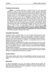
Series 185 Frequently Asked Questions
Service ..................................................................................................................................................................................... 3
How will I know if the controller is non-operational? .......................................................................................................... 3
What should I do if the indicator lights are faulty?............................................................................................................... 3
How do I contact a service technician? ................................................................................................................................ 3
Why won’t the engine exerciser light blink after setting (press and hold the button) the exerciser? ..................................... 3
Why doesn’t the engine exerciser light blink to indicate the remaining number of days until the next exercise period? ...... 3
Why won’t the generator shut down? .................................................................................................................................. 4
Why doesn’t the ATS transfer to emergency?...................................................................................................................... 4
Why won’t the engine start contacts work?.......................................................................................................................... 4
Why does the generator crank up when load is connected to the utility and then shuts down when utility fails? ................. 4
Why won’t the utility acceptable LED light up? .................................................................................................................. 4
Wiring ...................................................................................................................................................................................... 5
Where do I connect the engine start wires? .......................................................................................................................... 5
What generators are compatible with the series 185-transfer switch? .................................................................................. 5
Is the switch supplied with current limiting fuses? ............................................................................................................... 5
What is the DC voltage on the controller? ........................................................................................................................... 5
Features .................................................................................................................................................................................. 6
Are the time delays adjustable?............................................................................................................................................ 6
How do I specify the ATS?.................................................................................................................................................. 6
What is the 14A and 14B feature for? .................................................................................................................................. 7
What auxiliary features does the ATS offer? ....................................................................................................................... 7
Operation ................................................................................................................................................................................ 8
How do I set the engine exerciser?....................................................................................................................................... 8
How does the ATS work? .................................................................................................................................................... 8
How can I exercise with load? ............................................................................................................................................. 9
Why does the generator automatically shut-off? .................................................................................................................. 9
Rev. A
1
How do I perform a transfer test?......................................................................................................................................... 9
How does the engine exerciser work? .................................................................................................................................. 9
What does the engine exerciser light indicate?..................................................................................................................... 9
Will the 185-switch work with a non-generator emergency source? .................................................................................... 9
Product Installation ............................................................................................................................................................. 10
How do I install the ATS? ................................................................................................................................................. 10
Where is the ground bus located? ...................................................................................................................................... 11
Where do I connect the power cables? ............................................................................................................................... 11
Others.................................................................................................................................................................................... 12
Parts Inquiry ...................................................................................................................................................................... 12
Pricing Inquiry ................................................................................................................................................................... 12
Rev. A
2
Service
How will I know if the controller is non-operational?
1. The indicator lights are not showing proper indications.
2. The switch transfers even if there is no loss of utility power and no transfer test operation or exercise with transfer
is confirmed.
3. The relays are not operating according to the normal sequence (no voltage from the board socket to supply the
relay coils).
4. The engine exerciser has malfunctioned even if the battery is new, or exercises at a random schedule, or does
not function.
5. The generator would not start even when a start signal is verified or does not shut down.
6. The command buttons, DIP switches or potentiometers are non operational.
7. Discoloration or indication of damaged components visible on the circuit board.
8. Remote control switches are not functioning even though proper values have been set.
9. No power present at inputs from the harness.
Consult technical support group to verify the conditions
What should I do if the indicator lights are not functioning properly?
1. Check to determine if correct voltage is applied across the main contacts. This requires opening the enclosure
door and wearing the appropriate PPE.
2. Check that voltage sensing wires have continuity.
3. If the voltage across the terminals is acceptable, but the lights are not operational, then the controller should be
replaced.
Note: Checking these items requires an ASCO Services technician or a licensed electrician!
How do I contact a service technician?
1. You can contact a local ASI representative by calling the toll free hotline at (1-800-2726) and then go to option 2,
then option 3 on the prompt.
2. Customer service assistants can also transfer you to a technician’s office in your area.
Why won’t the engine exerciser light blink after setting (press and hold the button)
the exerciser?
1. Check engine start contacts to confirm they change position. If it doesn’t, controller may be non-conforming,
replace controller
2. If start contacts change position, generator may have a problem. Contact local generator distributor.
3. Check the 9-volt battery and the S2 dipswitch setting of the battery. It should be ON.
Note: Checking these items requires an ASCO Services technician or a licensed electrician!
Why doesn’t the engine exerciser light blink to indicate the remaining number of
days until the next exercise period?
1. After the exercise period stops, the flashing light will remain on to indicate that the exercise is enabled and another
exercise will be conducted after a week.
Rev. A
3
Why won’t the generator shut down?
1. Generator is still running on cool-down state. Approximately 5 minutes.
2. If the ATS has transferred to the utility source and the generator is still running after 5 minutes, check if generator
has its own cool-down timer/setting. Contact local generator supplier
3. If the generator has no cool-down timer but is still running after 5 minutes, check the engine start contacts on the
transfer switch.
4. If there is continuity on the N.O. contacts (no continuity on the N.C. contacts) and switch is connected to the utility
source, the controller may be non-conforming. Controller should be replaced.
Note: Checking these items requires an ASCO Services technician or a licensed electrician!
Why doesn’t the ATS transfer to emergency?
1. Verify that the generator accepted light is on. The ATS will not transfer load to an unacceptable source.
Check generator breaker. Contact local generator supplier.
2. Voltage across the emergency terminals is not acceptable.
3. The generator frequency is too low or too high.
4. The solenoid operator is non-operational.
5. The controller is non-operational.
Note: Checking these items requires an ASCO Services technician or a licensed electrician!
Why won’t the engine start contacts work?
Conduct a “transfer test.” The engine start contacts should change position. If they don’t, controller may need to be
replaced.
Contact an ASCO Services technician or a licensed electrician!
Why does the generator crank up when load is connected to the utility and then
shuts down when utility fails?
1. Controller does not sense the proper outage of the normal / utility source. May need to be replaced.
Why won’t the utility acceptable LED light up?
1. Normal/utility source is not acceptable. Voltage and/or frequency are not within acceptable parameters.
2. Utility breaker is OFF. Turn the breaker ON.
3. LED has malfunctioned; contact Parts Department or local distributor and replace LED.
Verify if the transfer switch harness is connected properly to the controller.
Note: Checking this item requires an ASCO Services technician or a licensed electrician!
Rev. A
4
Wiring
Where do I connect the engine start wires?
The generator starting contact connections are on the controller terminal block. Connect the generator start wires
to terminal block TB7 (TB7-4 and TB7-5 for normally open contacts, and TB7-5 and TB7-6 for normally closed
contacts)
Caution: Make sure both normal and standby source breakers are in the off position.
What generators are compatible with the series 185-transfer switch?
The Generator must be a 2 wire start and connect to the engine start circuit of the transfer switch.
Is the switch supplied with current limiting fuses?
No, suggested fuse ratings listed in table below:
NOTE: When properly coordinated with current-limiting devices, automatic transfer switches can be used on circuits having
available short-circuit currents greater than their unprotected withstand short-circuit current rating. Modern current limiting fuses,
when properly sized, limit the short-circuit current to within the withstand rating of a transfer switch.
What is the DC voltage on the controller?
24VDC.
Rev. A
5
Features
Are the time delays adjustable?
Refer to table for time delay settings.
How do I specify the ATS?
To specify the switch, just follow the Catalog number format below.
For Service Entrance
1AU
Product
Neutral
Code
Amperes
Phase
Continuous
Poles
Rating
1AUS*
A - Solid
Neutral
2 pole
1ø
Voltage
Code
Controller
200
C
F
400
Enclosure
240
4
M
Type 1
(Standard)
Type 3R
Secured
* Use product code 1APS to specify an optional additional circuit breaker on the emergency source.
Rev. A
6
What is the 14A and 14B feature for?
Transfer switch auxiliary position indicating contacts. One set of contacts to indicate the connection of
the transfer switch to the preferred (utility) source (14A) and one for the alternate (generator) source
(14B).
What auxiliary features does the ATS offer?
K373314 Auxiliary Switch Position Contact Kit 14A/14B, 100 through 230A only
Rev. A
7
Operation
How do I set the engine exerciser?
To set the exerciser:
1. Press and hold (5secs) the set Engine Exerciser button
2. The exercise period occurs immediately and at the same time weekly thereafter.
3. The status light below the button blinks rapidly to indicate that the exerciser has been set.
4. The number of flashes indicates the number of days until the next exercise periods (at approximately the same time
the button was pressed).
To cancel an active exercise period
1. Press the set engine exerciser button to stop an exercising generator. If exercise with load is set, the ATS
retransfers the load to the utility, then stops the generator after cool down
How does the ATS work?
See below ATS sequence of operation
Rev. A
8
How can I exercise with load?
1. Be sure the exerciser is turned on, and then select either exercise with or without load. Refer to the table for the
settings.
Caution: Make sure both normal and standby source breakers are in the off position before opening the
enclosure door to adjust any settings on the controller.
Why does the generator automatically shut-off?
1. Verify proper generator operation; it may have run out of fuel or shut down due to low oil
pressure.
2. Generator may be overloaded. Check if generator circuit breaker tripped. Check sum of load
to be sure it does not exceed the capacity of the generator.
3. Check the engine starting contacts.
Note: Checking these items requires an ASCO Services technician or a licensed electrician!
How do I perform a transfer test?
1. To perform a test, press and hold the transfer test button for at least 15 seconds or until the
generator cranks.
2. Wait for approximately 10 seconds for the transfer to generator time delay.
3. Press the Bypass Time Delay button for immediate load transfer to the generator.
How does the engine exerciser work?
1.
The engine exerciser works by closing the engine start contacts and keeps it closed in order to
crank and run the generator for approximately 20 minutes; after time expires, the controller
signals the engine start contacts to open up and shut the generator d o w n (after the 5
minute engine cool down period).
What does the engine exerciser light indicate?
1.
The status light below the set engine exerciser button blinks rapidly to indicate that the
exerciser has been set. The number of flashes indicates the number of days until the next
exercise period (at approximately the same time the button was pressed
Will the 185-switch work with a non-generator emergency source?
1.
Rev. A
YES, it will work with a non-generator emergency source. As long as you have provided
the necessary power cables to the transfer switch.
9
Product Installation
How do I install the ATS?
1. Mounting
Refer to the enclosure outline drawing. Mount the ATS according to details and instructions shown on this
diagram. Mount the ATS vertically to a rigid supporting structure. Level all mounting points by using flat
washers behind the holes to avoid distortion of the enclosure.
A
CAUTION
MALFUNCTI ON or SHORTENED LIFE
Protect the ATS from construction grit and metal chips to
prevent malfunction or shortened life.
Transfer switches rated 260 and 400 amperes are mounted on an insulator backing piece (installed behind
the transfer switch). If the transfer switch is removed from the enclosure and then reinstalled, this
insulator must be placed behind the transfer switch.. See Figure l.
A
WARNING
FLASH HAZARD- DAMAGE
Be sure that the insulator piece is installed behind the 260
and 400 ampere transfer switches.
0
0
0
Figure 1. Insulator for 260 and 400 A.
Rev. A
10
Where is the ground bus located?
1. Upon opening the enclosure door of the transfer switch, the ground bus / lugs are located on the right side of the
enclosure.
Caution: Do not open the enclosure door
Where do I connect the power cables?
Rev. A
11
Others
Parts Inquiry
1.
For parts inquiries, note the BOM number, Serial number. and Catalog number of the product and call 1-800-8002726 (ASCO) option 22. You may also visit: http://store.ascoparts.com/series165parts.html for more information.
Pricing Inquiry
1. To get pricing on the product, call 1-800-800-2726 (ASCO) option 31.
2. To check pricing and availability of a part, call 1-800-800-2726 (ASCO) option 2.
Rev. A
12