1
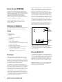
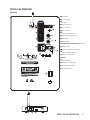
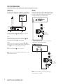
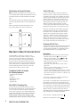
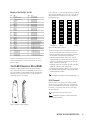
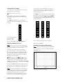
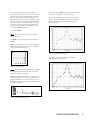
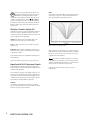
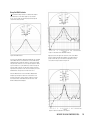
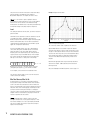
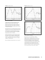
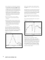
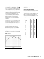
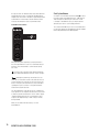
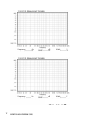
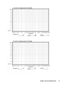
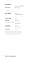
INFINITY CLASSIA
CoMPACT POWERED SUBWOOFER
™
OWNER’S GUIDE
PSW310W (120V)
IMPORTANT SAFETY PRECAUTIONS
READ FIRST!
1. Read these instructions.
2. Keep these instructions.
3. Heed all warnings.
4. Follow all instructions.
5. Do not use this apparatus near water.
6. Clean only with a dry cloth.
7. Do not block any ventilation openings. Install in
accordance with the manufacturer’s instructions.
8. Do not install near any heat sources such as radiators,
heat registers, stoves or other apparatus (including
amplifiers) that produce heat.
9. Do not defeat the safety purpose of the polarized or
grounding-type plug. A polarized plug has two blades with
one wider than the other. A grounding-type plug has two
blades and a third grounding prong. The wide blade or the
third prong is provided for your safety. If the provided plug
does not fit into your outlet, consult an electrician for
replacement of the obsolete outlet.
10. Protect the power cord from being walked on or
pinched, particularly at plugs, convenience receptacles
and the point where they exit from the apparatus.
11. Only use attachments/accessories specified by the
manufacturer.
12. Use only with the cart, stand, tripod,
bracket or table specified by the
manufacturer or sold with the apparatus.
When a cart is used, use caution when
moving the cart/apparatus combination to avoid injury from
tip-over.
13. Unplug this apparatus during lightning storms or when
unused for long periods of time.
14. Refer all servicing to qualified service personnel.
Servicing is required when the apparatus has been
damaged in any way, such as power supply cord or plug
is damaged, liquid has been spilled or objects have fallen
into the apparatus, or the apparatus has been exposed to
rain or moisture, does not operate normally or has been
dropped.
15. Do not expose this apparatus to dripping or splashing
and ensure that no objects filled with liquids, such as
vases, are placed on the apparatus.
16. To completely disconnect this apparatus from the
AC Mains, disconnect the power supply cord plug from
the AC receptacle.
17. The mains plug of the power supply cord shall remain
readily operable.
18. Do not expose batteries to excessive heat such as
sunshine, fire or the like.
The lightning flash with arrowhead symbol,
within an equilateral triangle, is intended to
alert the user to the presence of uninsulated
“dangerous voltage” within the product’s
enclosure that may be of sufficient magnitude to constitute
a risk of electric shock to persons.
The exclamation point within an equilateral
triangle is intended to alert the user to
the presence of important operating and
maintenance (servicing) instructions in
the literature accompanying the product.
WARNING: To reduce the risk of fire or electric shock,
do not expose this apparatus to rain or moisture.
FEDERAL COMMUNICATIONS COMMISSION
INTERFERENCE STATEMENT
This equipment has been tested and found to comply with
the limits for a Class B digital device, pursuant to Part 15
of the FCC Rules. These limits are designed to provide
reasonable protection against harmful interference in
a residential installation.
This equipment generates, uses and can radiate radio
frequency energy and, if not installed and used in
accordance with the instructions, may cause harmful
interference to radio communications. However, there
is no guarantee that interference will not occur in a
particular installation. If this equipment does cause harmful
interference to radio or television reception, which can
be determined by turning the equipment off and on, the
user is encouraged to try to correct the interference by
one of the following measures:
• Reorient or relocate the receiving antenna.
• Increase the separation between the equipment
and receiver.
• Connect the equipment into an outlet on a circuit
different from that to which the receiver is connected.
• Consult the dealer or an experienced radio/TV
technician for help.
ii
INFINITY CLASSIA PSW310W (120V)
FCC Caution: To assure continued compliance, any
changes or modifications not expressly approved by the
party responsible for compliance could void the user’s
authority to operate this equipment. (Example – use only
shielded interface cables when connecting to computer
or peripheral devices.)
FCC Radiation Exposure Statement
This equipment complies with FCC RF radiation exposure limits
set forth for an uncontrolled environment. This equipment
should be installed and operated with a minimum distance
of 20 centimeters between the radiator and your body.
This device complies with Part 15 of the FCC Rules.
Operation is subject to the following two conditions:
(1) This device may not cause harmful interference, and
(2) This device must accept any interference received,
including interference that may cause undesired operation.
INFINITY CLASSIA PSW310W OWNER’S GUIDE
™
Table of Contents
ii
Important Safety Precautions
1
Unpacking the Subwoofer
1
Placement
2
Controls and Connections
3
System Connections
4
Operation
5
Room Adaptive Bass Optimization System (R.A.B.O.S.)
6
Contents of the R.A.B.O.S.Test CD
6
The R.A.B.O.S. Sound-Level Meter (RSLM)
6
RSLM Placement
7
Initial System-Level Setting
7
Setting the Subwoofer Test Level
7
Performing Low-Frequency Measurements
9
What Does a Parametric Equalizer Do?
9
Completing the R.A.B.O.S. Measurement Template
10
Using the Width Selector
11
Level
11
What You Measure, What to Do
14
Adjusting the R.A.B.O.S. Equalizer
15
Final System Balance
16 Maintenance and Service
17 R.A.B.O.S. Measurement Templates
19 Specifications
INFINITY CLASSIA PSW310W (120V)
iii
INFINITY CLASSIA PSW310W
™
The Infinity Classia PSW310W continues the legendary Infinity®
dedication to accurate sound reproduction.The patented Ceramic
Metal Matrix Diaphragm (CMMD®) drivers, high-powered amplifier
and proprietary Room Adaptive Bass Optimization System™
(R.A.B.O.S.™) technology, along with a rigid, well-braced
enclosure, combine to deliver uncompromised bass performance
in any stereo or multichannel home theater.
In addition, the PSW310W’s compact enclosure and
wireless capability allow for easy integration into any
residential environment.
UNPACKING THE SUBWOOFER
Here are several additional facts on installation that may prove
useful. It is generally believed by most audio authorities that low
frequencies (below 125Hz) are nondirectional and, therefore,
placement of a subwoofer within any listening room is not
critical. While in theory it is true that the larger wavelengths of
extremely low frequencies are basically nondirectional, the fact
is that, when installing a subwoofer within the limited confines
of a room, reflections, standing waves and absorptions generated
within the room will strongly influence the performance of any
subwoofer system. As a result, the specific location of the
subwoofer becomes important, and it is strongly recommended that
you experiment with placement before choosing a final location.
Placement will depend upon your room and the amount and
quality of bass required (for example, whether or not your room
permits placement of the subwoofer near either satellite).
SUB
If you suspect damage from transit, report it immediately to your
dealer. Keep the shipping carton and packing materials for
future use.
RIGHTCHANNEL
SPEAKER
Included
1 x Owner’s manual
1 x USA warranty sheet
1 x Subwoofer
1 x 15' (4.5m) Audio cable, RCA-RCA
4 x Spiked feet
1 x Transmitter module
1 x Power supply for transmitter
1 x 120V two-prong AC power cord for transmitter power supply
1 x 6' Audio cable, RCA-RCA
1 x Wall-mount bracket for transmitter
2 x With two panhead M3 x 4 machine screws for attaching
wall-mount bracket to transmitter
4 x Small, round, self-adhesive feet – to be attached on
transmitter’s left-side panel if transmitter is to be
used vertically
PLACEMENT
Since the installation of a subwoofer can be somewhat more
complicated than installing full-range speakers, it is essential
that you read this section very carefully prior to connecting the
subwoofer to your system. Should you have questions relating to
your installation, it is advisable to call either your dealer or the
Infinity Customer Service Department for advice.
The performance of the subwoofer is directly related to its
placement in the listening room and how you align the subwoofer
with its satellite speakers.The PSW310W’s wireless capability
makes it even easier to properly locate the subwoofer in your
room. Setting the volume of the subwoofer in relation to the left
and right speakers is also of critical importance because it is
essential that the subwoofer integrate smoothly with the entire
system. Setting the subwoofer’s volume level too high will result
in an overpowering, boomy bass. Setting the volume level too low
will negate the benefits of the subwoofer.
1
INFINITY CLASSIA PSW310W (120V)
PRIMARY
LISTENING
AREA
Figure 1.This example shows the subwoofer positioned behind
the right-channel satellite speaker to re-create the actual
location of bass instruments in an orchestra and/or add impact
to movie soundtracks.
INSTALLING SPIKED FEET
Four metal spikes are supplied for use when the subwoofer is to
be placed on a carpeted surface to decouple the subwoofer from
the floor and prevent unwanted damping.To insert the spikes, gently
lay the subwoofer on its back (not on its front or side) on a soft,
nonabrasive surface. Each spike screws into the threaded insert.
Make sure all four spikes are screwed in completely for stability.
NEVER drag the subwoofer to move it, as this will damage the spikes,
the feet, the wood cabinet itself and/or the floor. Always lift the
subwoofer and carry it to its new location.
CONTROLS AND CONNECTIONS
Rear Panel
¡ Power Switch
™ Line-Level Inputs
£ LFE Input
‚
A nte nna
¤
Frequency
¢ Power Indicator LED
⁄
Off
On
∞ Low-Pass Selector
Phase
ª
C
§ ID-Code Selector
Level
¶ Crossover Adjustment Control
Width
•
• Subwoofer-Level (Volume) Control
D
ª Phase Switch
Level
Crossover
[Hz]
¶
‚ Wireless Antenna
Room Adaptive Bass Optimization Controls (see page 5)
Wireless
§
O ff
ID Code
A R.A.B.O.S. Selector
∞
On
Low-Pass
Green: Sub On
Red: Standby
Orange: Sub On and
Wireless Link Active
¢
™
L
R
LFE
£
Sub In
¤ R.A.B.O.S. Center-Frequency Adjustment
C R.A.B.O.S. Bandwidth Adjustment
D R.A.B.O.S. Level Adjustment
Transmitter
PSW310W
E Transmitter Antenna
F Transmitter Power-Supply Input
G Transmitter ID-Code Selector
Power
H Transmitter Sub Input
On
¡
Off
AC 120V~60Hz
2A
ID
CODE
DC18V
1 2 3 4
E
F
G
Sub In
H
INFINITY CLASSIA PSW310W (120V)
2
SYSTEM CONNECTIONS
Choose either Wireless or Wired connection, then follow the appropriate instructions.
WIRELESS
WIRED
Connecting the Subwoofer for Wireless Applications
Connecting the Subwoofer for Wired Applications
If you have a Dolby® Digital or DTS® receiver/processor with
a low-frequency effects (LFE) or subwoofer output:
Level
Crossover
[Hz]
ID
CODE
DC18V
1 2 3 4
Sub In
Wireless
Offff
O
ID Code
Step 1.
Connect a subwoofer cable from the subwoofer or LFE output of
your receiver to the Sub In H on the transmitter.
OOnn
Low-Pass
Low-Pass
L
Sub In
R
LFE
Green: Sub On
Red: Standby
Orange: Sub On and
Wireless Link Active
Line In
Step 2.
Plug the transmitter module into the wall outlet, and connect the
included power supply and power cord to the transmitter F. Make
sure the Transmitter Antenna E is extended upward.
Step 3.
Set the ID code on the transmitter and subwoofer (G and §) to
the same position, as described on page 4. When connected properly,
the LED ¢ on the rear of the subwoofer will be orange.
If your receiver/processor does not contain a Dolby Digital
or DTS processor but has subwoofer outputs:
Step 4.
Set the Low-Pass Selector ∞ to the “Off” position.
Level
NOTE: Some receivers have two subwoofer outputs. In that case, use
either one of the connectors.
Crossover
[Hz]
Wireless
Off
ID Code
On
Low-Pass
L
Sub In
R
Green: Sub On
Red: Standby
Orange: Sub On and
Wireless Link Active
LFE
Line In
NOTE: If your receiver/processor has only one sub out, you
may use either the L or R input.
3
INFINITY CLASSIA PSW310W (120V)
OPERATION
Power On
Connect your signal source (such as an A/V receiver or preamplifier)
to the transmitter (if using wireless connection) or to the subwoofer
(if using wired connection).Two single-RCA cords are provided. While
you would ordinarily use the short cable to connect to the transmitter
or the long one to connect to the subwoofer, either cable can be
used, depending on proximity to the signal source.There is no need
or benefit gained from connecting the same source to both the
transmitter and the subwoofer. However, you could connect two
separate sources to this subwoofer by utilizing both its wired and
wireless connections. Both signals will essentially be mixed and
outputted by the subwoofer. Plug your transmitter’s (if using wireless
connection) and subwoofer’s AC cord into a wall outlet. Do not use the
outlets on the back of the receiver for the subwoofer.
Initially set the Subwoofer-Level Control • to the “Min” position.
Turn on your sub by pressing the Power Switch ¡ on the rear panel.
Turn on your entire audio system and start a CD or movie soundtrack
at a moderate level.
Auto On/Standby
Transmitter (wireless connection only):The Power Indicator LED
(not shown) will be lit in red when the unit is in standby. When the
transmitter receives an audio signal from the source, it will immediately
turn on and the LED will turn to blinking green or solid green:
RED = STANDBY (No signal detected, transmitter off)
GREEN (BLINKING) = Transmitter is on but has not established a link
with the wireless sub.
GREEN (SOLID) = Transmitter is on and has already established a link
with the wireless sub.
The transmitter will automatically enter Standby mode after approximately
10 minutes when no signal is detected from your system.
Subwoofer: With the Power Switch ¡ in the “On” position, the Power
Indicator LED ¢ on the back panel will remain lit to indicate the
On/Standby mode of the subwoofer.
RED = STANDBY (No signal detected, amp off)
GREEN = SUB ON (Wired signal detected, amp on)
ORANGE = SUB ON (Wireless link with transmitter active)
The subwoofer will automatically enter Standby mode after
approximately 10 minutes when no signal is detected from your
system.The subwoofer will then power on instantly when a signal is
detected. During periods of normal use, the Power Switch ¡ can be
left on.You may turn off the Power Switch ¡ for extended periods of
nonoperation, e.g., when you are away on vacation.
Getting Started
Confirm that the Status LED on the transmitter (not shown) is on (red
or green) and the Status (Power Indicator) LED ¢ on the subwoofer
is on (red, orange or green) and that an RCA cable is connected
from a source unit to either the LFE Input £ of the subwoofer or
transmitter H or L and R inputs ™ on the subwoofer. Play a CD or
video. Use a selection that has ample bass information. If using a
wireless connection, the Status LED on the transmitter should be lit
in solid green, and the Status LED ¢ on the subwoofer should turn
orange if connected wirelessly. If the LED on the transmitter is blinking
in green and the LED on the subwoofer is in red or green, a wireless
link has not been established between the transmitter and the
subwoofer. If connecting directly to the subwoofer without using the
wireless link, the Status LED ¢ on the subwoofer should be lit green.
If the LED on the subwoofer remains red, check that the RCA cable from
the source to the subwoofer (wired connection) or transmitter (wireless
connection) is functioning properly (wired connection) and that it is
fully inserted at both ends, or that the Transmitter ID-Code Selector G
and the Subwoofer ID-Code Selector § are set to the same channel.
Once you have a green or orange LED on the subwoofer, turn your
Subwoofer-Level Control • up halfway so that the knob indicator
points up.You should now be hearing bass information coming from
the subwoofer.
Adjust Level
Set the overall volume control of the preamplifier or stereo to a
comfortable level. Adjust the Subwoofer-Level Control • until you
obtain a pleasing blend of bass. Bass response should not overpower
the room but rather be adjusted so there is a harmonious blend across
the entire musical range. Many users have a tendency to set the
subwoofer volume too loud, adhering to the belief that a subwoofer
is there to produce lots of bass.This is not entirely true. A subwoofer
should enhance bass, extending the response of the entire system
so the bass can be felt as well as heard. However, overall balance
must be maintained or the music will not sound natural. An experienced
listener will set the volume of the subwoofer so its impact on bass
response is always there but is never obtrusive.
Phase Control
The Phase Switch ª determines whether the subwoofer driver’s
piston-like action moves in and out with the main speakers, 0˚, or
opposite the main speakers, 180˚. Proper phase adjustment depends
on several variables such as room size, subwoofer placement and
listener position. Adjust the Phase Switch ª to maximize bass output
at the listening position.
Crossover Adjustment
The Crossover Adjustment Control ¶ determines the highest frequency
at which the subwoofer reproduces sounds. If your main speakers can
comfortably reproduce some low-frequency sounds, set this control
to a lower frequency setting, between 50Hz and 100Hz.This will
concentrate the subwoofer’s efforts on the ultradeep bass sounds required
by today’s films and music. If you are using smaller bookshelf speakers
that do not extend to the lower bass frequencies, set the Crossover
Adjustment Control ¶ to a higher setting, between 120Hz and 150Hz.
NOTE: This control will have no effect if the LFE Input £ is used
(wired connection) or if the Low-Pass Selector ∞ is in the “OFF”position
(wireless connection). If you have a Dolby Digital or DTS processor/
receiver, the low-pass frequency is set by the processor/receiver. Consult
your owner’s manual to learn how to view or change this setting.
ID Codes
In the unlikely event that you experience interference when operating
the system, or if you have more than one set of subwoofer transmitters
and receivers in operation, you may change the channel in which the
system operates. On the transmitter module and the subwoofer, there is
a four-position ID-Code Selector (G and §). Simply set the selectors
to one of the other positions.The transmitter and subwoofer (G and §)
selectors must be set to the same position for the system to function
correctly.You can also set up a maximum of two subwoofers to be
receiving from the same transmitter by setting the channel selector
on the transmitter and both of the subwoofers to the same channel.
A Word About Wireless Products
The Infinity Classia PSW310W wireless subwoofer utilizes advanced
wireless transceivers operating in the 2.4GHz frequency band.This is
the same frequency band that is used for wireless home networks and
high-quality cordless phones. It also allows for the transmission of highperformance, full-spectrum sound to remote locations, wirelessly.
Like all wireless devices, the Infinity PSW310W wireless subwoofer’s
operating range may vary, depending upon variables such as building
construction methods and materials, atmospheric conditions and other
sources of interference. Please consult your Infinity dealer or distributor,
or visit www.infinitysystems.com, for further information or assistance.
INFINITY CLASSIA PSW310W (120V)
4
Wall-Mounting the Transmitter Module
The R.A.B.O.S. Goal
NOTE: The customer is responsible for the correct selection and
use of mounting hardware (available through hardware stores) that
will ensure the proper and safe wall-mounting of the transmitter.
It is a fact of audio that what we hear at low frequencies is
determined as much or more by the listening room than by the
loudspeaker itself. Placement of the loudspeakers and listeners
and the acoustical characteristics of the room surfaces are all
important determinants of bass quantity and quality. In most
practical situations, there is little that can be done about this,
except for patient trial-and-error repositioning of the loudspeakers and listeners. Usually, the practical constraints
of a living space and the impracticality of massive acoustical
treatment mean that equalization is the only practical solution.
Step 1.
Insert the two M3 x 4 machine screws through the wall bracket and
into the rear of the transmitter module, as shown in the figure below.
Step 2.
Attach the transmitter module with wall bracket to the wall,
using suitable hardware and, if necessary, wall anchors.
Professional sound engineers routinely employ sophisticated
measurement systems and equalizers to optimize speakers to
the installation.This has never been practical for the home
audiophile.This is why R.A.B.O.S. technology was created. It
enables you to identify the dominant low-frequency response
characteristic of your room. Once you know the problem, the
R.A.B.O.S. system provides the tools needed to optimize the
low-frequency characteristics of the speakers to the room they
are in, exactly as the professional sound engineers do it.
Performing R.A.B.O.S.Tests
These instructions assume you have already installed your subwoofer
according to the information provided in the owner’s guide. It is
also assumed that all equipment in your entertainment system is
interconnected properly and is in good operating condition.
ROOM ADAPTIVE BASS OPTIMIZATION SYSTEM
™
™
The Infinity R.A.B.O.S. technology is a simple-to-use, yet
sophisticated, low-frequency calibration system. It is designed
to work in conjunction with the Infinity Classia PSW310W
powered sub.The subwoofer contains a parametric equalizer
that you will adjust as indicated by the R.A.B.O.S. test results.
By following these instructions, you will optimize the subwoofer’s
response characteristics to complement the sub’s environment.
This will dramatically improve the sound of your system.The
optimization process takes less than 30 minutes.
The Optional R.A.B.O.S. Kit Includes
the Following Components:
• Specialized Sound-Level Meter
• Test CD
• Instructions
• Measurement Templates
• Width Selector
• Adjustment “Key”
What R.A.B.O.S.Technology Does
The Test CD provides specially designed signals you will use
while performing measurements.The sound-level meter provided
is used to “acquire” the information needed for adjustments.
You will create a response plot on the R.A.B.O.S. Measurement
Template. Using the Width Selector, you will then determine the
appropriate equalizer settings.The Adjustment “Key”is used to
adjust the parametric equalizer built into the PSW310W.After
adjustment, the test sequence is repeated to confirm your settings.
5
INFINITY CLASSIA PSW310W (120V)
Preparations
Before beginning R.A.B.O.S. tests, please check the following:
• Set R.A.B.O.S. System Selector ⁄ to the “On” position.
• Make sure all three R.A.B.O.S. controls (¤, C and D)
on the subwoofer are turned fully clockwise.
• Make sure the loudness contour (if any) on your receiver/
processor/preamp is turned off.
• Set the tone controls (Bass and Treble) to their center or
flat positions.
• Bypass all surround and effects features of your receiver/
processor/preamp or set to “Stereo Bypass.”
• If you are using a multichannel surround processor or receiver,
make sure all bass-management features are properly set.The
Audio channels should all be set to “Small” or “High-Pass” and
the subwoofer set to “On.”
You must have a CD player in the system. A CD player remote
control is quite convenient but not essential.
For best results, it is recommended that all major furnishings are in
place and that all doors and windows in the listening area are in
their normal positions.That is, if you normally listen to music with all
doors closed, then this is how they should be during this procedure.
Try to minimize ambient noise while running tests.Turn off all major
appliances and any air conditioning or furnace fans.These can
create significant subsonic noise that may be barely perceptible but
which can wreak havoc on low-frequency measurements.
Critical information is highlighted with this mark:
Helpful hints are marked with this symbol:
Contents of the R.A.B.O.S. Test CD
Track
1
2
3
4
5
6
7
8
9
10
11
12
13
14
15
16
17
18
19
20
21
22
23
24
25
26
27
28
29
30
31
Title
Welcome
Set System Test Level
Set Subwoofer Test Level
100Hz Test
95Hz Test
90Hz Test
85Hz Test
80Hz Test
77Hz Test
72Hz Test
66Hz Test
63Hz Test
56Hz Test
52Hz Test
49Hz Test
46Hz Test
43Hz Test
40Hz Test
38Hz Test
35Hz Test
30Hz Test
26Hz Test
24Hz Test
22Hz Test
21Hz Test
20Hz Test
Intro to Quick Retest
Quick Retest 100Hz
Quick Retest 95Hz
Quick Retest 90Hz
Quick Retest 85Hz
Track
32
33
34
35
36
37
38
39
40
41
42
43
44
45
46
47
48
49
50
51
52
53
54
55
56
57
58
59
60
61
62
Title
Quick Retest 80Hz
Quick Retest 77Hz
Quick Retest 72Hz
Quick Retest 66Hz
Quick Retest 63Hz
Quick Retest 56Hz
Quick Retest 52Hz
Quick Retest 49Hz
Quick Retest 46Hz
Quick Retest 43Hz
Quick Retest 40Hz
Quick Retest 38Hz
Quick Retest 35Hz
Quick Retest 30Hz
Quick Retest 26Hz
Quick Retest 24Hz
Quick Retest 22Hz
Quick Retest 21Hz
Quick Retest 20Hz
Final System-Level Adjustment
Final Subwoofer-Level Adjustment
Wide Band Pink Noise, Left
Wide Band Pink Noise, L+R
Wide Band Pink Noise, Right
Wide Band Pink Noise, L-R
Wide Band Pink Noise, Uncorrelated
1 to 4kHz Pink Noise, Left
1 to 4kHz Pink Noise, L+R
1 to 4kHz Pink Noise, Right
1 to 4kHz Pink Noise, Left-R
1 to 4kHz Pink Noise, Uncorrelated
Tracks 53–62 of the R.A.B.O.S.Test CD are test tones that can be
used for general diagnostics of your system.They are not used for
R.A.B.O.S. settings.
THE R.A.B.O.S. SOUND-LEVEL METER (RSLM)
The RSLM is a battery-operated, handheld, acoustic measurement
device specifically designed for the Infinity R.A.B.O.S. system. On the
face of the instrument is a light-emitting diode (LED) bar graph that
indicates relative sound level.There are also indicators for power-on,
out-of-range signals and a low battery.
Power is switched on or off by pressing the button directly below
the bar-graph window. When the unit is on, one or more LEDs will
always be illuminated.The function of the LEDs is described in
the following section.
0dB
-1
-2
-3
-4
-5
-6
-7
-8
-9
-10
-12
-14
-16
ON
Batt
0dB
-1
-2
-3
-4
-5
-6
-7
-8
-9
-10
-12
-14
-16
ON
Batt
0dB
-1
-2
-3
-4
-5
-6
-7
-8
-9
-10
-12
-14
-16
ON
Batt
0dB
-1
-2
-3
-4
-5
-6
-7
-8
-9
-10
-12
-14
-16
ON
Batt
On
Under-Range
Measurement
In-Range
Over-Range
Low
Battery
Figure 3. RSLM bar-graph indications
• Power-On/Low Signal: This is indicated by the illumination of
any LED on the bar graph. If the sound level in the room is
below the measurement range of the instrument, a green LED
near the bottom of the bar graph will be illuminated.
• Normal Measurements: When the sound level is within the
range of the RSLM, the green LED will be off and one of the
red LEDs in the bar graph will be illuminated, indicating the
relative sound level, in decibels (dB).
• Over-Range: If the sound level exceeds the range of the meter,
0dB through –5dB will all light simultaneously.
• Low Battery: When the battery voltage is too low for accurate
measurements, an LED at the bottom of the bar graph will be
illuminated. Replace the battery.
Do not attempt measurements when the Low Battery light is on.
RSLM Placement
-1
-2
-3
-4
-5
-6
-7
-8
-9
-10
-11
-13
-15
-18
U-R
Batt
Power
Determine where in the room you are most likely to sit when
listening to music or watching a movie.This is where you will
want to hold the RSLM during measurements.The RSLM should
be oriented so it can be easily read and held at your seated
ear level during tests.
You must use this same position for all tests.
The RSLM can be mounted on a standard camera tripod.
This will ensure the best results.
Figure 2. R.A.B.O.S. Sound-Level Meter
INFINITY CLASSIA PSW310W (120V)
6
Initial System-Level Setting
The following steps will set the playback level of the system to
the correct level for all tests that follow.
Turn the system volume to minimum.
Cue the R.A.B.O.S.Test CD to Track 2 and press Pause II.This
track will produce band-limited pink noise in both the left and
right channels.
Press Play ›. With the RSLM positioned as described above,
increase the system volume until the RSLM display indicates –10dB.
See Figure 4.
Figure 4. RSLM indicating the
correct system level to
begin tests (–10dB)
0dB
-1
-2
-3
-4
-5
-6
-7
-8
-9
-10
-12
-14
-16
ON
Batt
sound bad; they can cause measurement errors. If you hear a
buzz or rattle during this test, it is highly recommended that you
locate the source and eliminate its effects.This is actually a
valuable room-diagnostic tool.
Press Play ›. As Track 3 plays, watch the RSLM carefully. Watch
for peak readings.The peak reading may be no more than a brief
flash. Readjust the subwoofer’s Subwoofer-Level Control • until
the peak level observed is 0dB without triggering the over-range
indication. See Figure 5.
0dB
-1
-2
-3
-4
-5
-6
-7
-8
-9
-10
-12
-14
-16
ON
Batt
0dB
-1
-2
-3
-4
-5
-6
-7
-8
-9
-10
-12
-14
-16
ON
Batt
Too Low
Correct
Level
0dB
-1
-2
-3
-4
-5
-6
-7
-8
-9
-10
-12
-14
-16
ON
Batt
Too High
Figure 5. Adjusting the subwoofer levels for a 0dB peak
When you have completed this adjustment, press Pause II.
Setting the Subwoofer Test Level
When finished, press Pause II.
Each of the following test tracks is about one minute
long.This is normally much longer than required. Press Pause II
or advance to the next test as soon as you are ready.
Performing Low-Frequency Measurements
This step will set the subwoofer levels for measurement
purposes.The objective is to scale the subwoofer’s output to
make full use of the RSLM indicator range. Scaling is optimum
when a 0dB reading is observed on the highest peak without
triggering the over-range indication. Later, you will rebalance
the subwoofer to the main speakers.
Read the following instructions fully before beginning tests.
For the following steps, you will need a R.A.B.O.S. Measurement
Template and a pencil.
The three R.A.B.O.S. controls, ¤, C and D, should be
set to fully clockwise positions, and all measurements should be
conducted with their level controls in this position. Confirm this
setting before you begin this test.The Subwoofer-Level Control •
should be set to the mid position.
Cue Track 3 and Pause II.Track 3 continuously steps through all
subwoofer test tones for approximately one minute. Each tone will
play just long enough for the RSLM to give a stable reading.
To get accurate measurements, it is necessary to play
the subwoofer quite loud.The 0dB indication is about 94dB. At
this level, frequencies below 100Hz can cause doors, windows,
furnishings and other objects in the room to vibrate.This
frequently results in clearly audible buzzes and/or rattles that
come and go as each test tone plays. Strong buzzes not only
7
INFINITY CLASSIA PSW310W (120V)
Figure 6. R.A.B.O.S. Measurement Template
Each of the following tracks produces a low-frequency test
tone.The range of these tests is from 100Hz down to 20Hz.The
frequency of each test is announced before it begins.The first
test is the highest frequency (100Hz); therefore, you will be
marking the template from right to left. Each frequency point is
listed across the bottom of the R.A.B.O.S. Measurement Template
(this is called the X-axis). See Figure 6 on the previous page.
The vertical scale on the left side of the template indicates
relative level, in dBs (the Y-axis).The template’s vertical scale
matches that of the RSLM bar graph.
When finished, press Skip ››I to advance to the next test. Repeat
the process described above for Tracks 5 through 26.
When you have completed the 23 measurements, you are ready to
analyze the data and make corrective adjustments.The completed
R.A.B.O.S. Measurement Template will look something like the
example in Figure 9.
Cue Track 4 and Pause II.
From now on, you will want to keep your CD player’s
remote control handy.
Press Play ›. As Track 4 plays, observe the level indicated on
the RSLM.
EXAMPLE:The test frequency is 100Hz and the level indicated is
–2dB. Find the intersection of 100Hz (X-axis) and –2dB (Y-axis).
Place a dot at that point. See Figure 7.
Figure 9. Completed R.A.B.O.S. template
Now connect the dots as shown in Figure 10.This will make
interpretation of the data much easier.
Figure 7. Locating a test point
It takes a few seconds for the RSLM reading to stabilize,
especially at very low frequencies. Don’t rush. Give each test
adequate time for the meter to stabilize.
At the bottom of the bar graph is a green “On” LED.This LED is
illuminated whenever the sound level is below the measuring
range of the RSLM. If this occurs during a test, place a dot at
the intersection of the test frequency and the bottom frame of
the template. See Figure 8.
Figure 10.Test example with dots connected
2
Figure 8. Indicating an under-range test
INFINITY CLASSIA PSW310W (120V)
8
At this point, you may simply enter the data you just
measured into the R.A.B.O.S. calculator, found on the
Infinity Web site at www.infinitysystems.com. After
entering the data, this R.A.B.O.S. wizard will return the correct
settings for all three R.A.B.O.S. controls: ¤, C and D. Skip
to page 14 and adjust these controls as described, and finish
the R.A.B.O.S. setup. If you would like to manually calculate the
R.A.B.O.S. settings, simply continue following the instructions
from this point.
STOP
Width
The frequency range of the R.A.B.O.S. equalizer may be set from
5% to 50% of an octave in 21 steps.This setting defines how
much of the PSW310W’s output will be equalized.
What Does a Parametric Equalizer Do?
The R.A.B.O.S. system uses one band of parametric equalization
for response correction. Parametric equalizers are the most
versatile class of filters.The effect an equalizer will have on the
signal is dependent on three parameters.
Frequency: The equalizer will have maximum effect at one
frequency, usually described as the center frequency.
Level: This refers to the amount of cut (in dBs) for which the
equalizer is set.
Bandwidth: Defines the range of frequencies over which the
equalizer will have an effect. On the PSW310W, this adjustment
is abbreviated as “Width.”
Only parametric equalizers allow independent adjustment of all
three parameters.
Width is expressed as a percentage of an octave. For example, a
width setting of 25% means the equalizer will affect a frequency
band of 1/4 of an octave; 1/8 of an octave above and 1/8 of an
octave below the center frequency.
Completing the R.A.B.O.S. Measurement Template
The octave is a logarithmic expression. From any point
in the spectrum, one octave above or below that point is always
double or half the frequency.Therefore, one octave above 100Hz
would be 200Hz. One octave below 100Hz is 50Hz.
Along the bottom of the R.A.B.O.S. Measurement Template are
three fields where you will enter the equalizer settings needed to
complete system optimization.
In the section that follows, we will discuss the use of the
Width Selector.
These will be explained more fully in the sections that follow.
These instructions are based on the example in Figure 11. Use
this tutorial to become familiar with the process. Strategies for
several other test results will be presented later. After you have
completed these three entry fields, you will be ready to perform
the adjustments, completing R.A.B.O.S. optimization.
Frequency
The frequency of the R.A.B.O.S. equalizer may be adjusted to
any one of nineteen frequencies from 20Hz to 80Hz.This defines
where you are going to apply equalization.
9
Figure 11. Effect of adjustable width
INFINITY CLASSIA PSW310W (120V)
Using the Width Selector
Read the following instructions carefully.The example
presented may not look like the graph you just created.
Focus on the concepts and techniques presented. Specific
cases will be discussed later.
Figure 13. Placement of the Bandwidth Selector
Figure 12. Width Selector
You will use the R.A.B.O.S. Measurement Template just completed
and the Width Selector to determine the correct width setting.
The Width Selector graphically depicts a single resonant peak.
The peak looks similar to a slice of a pie. See Figure 12. At the
top of the Selector is a pull tab. When you slide the tab up and
down, the width of the pie slice becomes narrower and wider,
respectively.The pointers on the sides of the button point to the
bandwidth that corresponds to the width of the slice.
Apply pressure to the upper and lower left corners of the Width
Selector using the thumb and forefinger of your left hand. Now
gently slide the tab up or down until the adjustable slice most
closely fits the response data. See Figure 14.
Place the Width Selector over the R.A.B.O.S. Measurement
Template, positioning the center rivet of the Selector over
the response peak, as shown in Figure 13. Be sure to align
the horizontal lines of the Width Selector with those of the
R.A.B.O.S. Measurement Template.
Figure 14. Selector adjusted for the “best fit”
INFINITY CLASSIA PSW310W (120V)
10
The pointer on the slider will indicate the correct width setting.
Enter this number in the Width field of the R.A.B.O.S.
Measurement Template. In our example, the width is 12.5%.
Example 1. Single Dominant Peak:
It is not realistic to expect a perfect fit. Acoustic
measurements encompass the behavior of not only the speakers
but of the room and its contents as well. Reflected energy,
standing waves and ambient noise all add their part. Determining
the best width setting nearly always requires compromise.
Level
This setting will define the amount (level) you want to reduce the
peak, in decibels.
The R.A.B.O.S. level adjustment is limited to attenuation only, and
is adjustable from 0dB to –14dB. After optimization, the
R.A.B.O.S. equalizer will eliminate the largest low-frequency peak;
therefore, the broadband bass level can be increased without
overpowering the midrange frequencies.The R.A.B.O.S. system
applies this compensation automatically.
This is the most common result of speaker/room interaction.
You will use the Width Selector as an aid in determining the
correct level setting. Place the Width Selector as described
above and adjust it to the correct width. Observe the first
frequency point on the high-frequency side of the peak that no
longer follows the slope of the Width Selector. In this example,
this is 56Hz. Calculate the average level of the readings from
56Hz up to 100Hz; that is, 10 data points in this example.
Apply the Width Selector as described in Figure 13. Align the
center-line of the Selector over the center of the peak, as shown
in Figure 14. Now adjust the Selector until you have achieved the
“best fit.”The slider now points to the correct bandwidth setting.
In this example, the frequency is 43Hz and the best-fit width is
12.5%. Fill in the Width and Frequency fields provided on the
template.
56Hz 63Hz 66Hz
–9 –10 –8
72Hz 77Hz 80Hz 85Hz 90Hz 95Hz 100Hz
–9 –10
–9
–8 –10 –10
–9
– 92 ÷ 10 = –9.2
Whenever your answer has a remainder, always round down
(disregarding the negative [–]) to the next whole number.
In our example, you would enter 9 in the attenuation field.
This may not be the best method in all cases.The next section
contains several other examples.
What You Measure, What to Do
As stated earlier, it is not possible to anticipate the effect of
every possible listening environment. However, most residential
sound rooms share many characteristics, and their dimensions
fall into a range that make some response irregularities far more
likely than others. On the following pages are examples of what
you may encounter. Following each example is a strategy for
correction. Compare your measurement results with the following
examples. Find the one that best fits your graph and follow the
instructions presented for that scenario.
Remember, when looking for a match, look at the
descriptive characteristics, not any specific frequency or level.
Each of these examples can occur at any frequency, bandwidth
and level. It is unlikely that your test results will be exactly as
depicted in these examples.
11
INFINITY CLASSIA PSW310W (120V)
Figure 15. Single dominant peak
Determine the appropriate level using the technique described
earlier. In this example, –9dB would be best. Enter the level in
the field provided.
Skip to the “Adjusting the R.A.B.O.S. Equalizer” section on page 14.
Example 2. Two Response Peaks:
Example 3. Peak Adjacent to a Dip:
Figure 16.Two response peaks
Characterized by two response peaks, approximately equal in
amplitude and width.This requires that you make a choice
between the two peaks. In situations like this, the higher
frequency peak will always be more audible and objectionable.
Response peaks below 45Hz, unless extreme, can actually be
beneficial toward achieving visceral impact. Perform corrections
on the upper frequency peak.
Apply the Width Selector as described above. Align the center-line
of the Selector over the center of the higher frequency peak. Now
adjust the Selector until you have achieved the “best fit.”The
slider now points to the correct width setting. In this example,
this is at 52Hz.The best-fit width is 28%. Fill in the Width and
Frequency fields provided on the template.
Determine the appropriate level using the technique described
earlier.This calculation will indicate a –8dB setting. However,
this peak does not reach the 0dB level as the lower peak does.
Therefore, a –8dB setting would be excessive.The 52Hz peak
stops at –2dB. Subtracting 2 from 8 yields the correct setting,
–6dB. Enter –6 in the Level field.
Skip to the “Adjusting the R.A.B.O.S. Equalizer”section on page 14.
Figure 17. Dip above or below peak
Response dips can occur at any frequency, sometimes
immediately adjacent to the peak you want to correct.Two
examples are shown, one immediately above and one immediately
below the peak. Deep response dips such as these are caused
by destructive wave interference. Destructive interference dips
occur only in one spot within the room. It is not uncommon to
completely eliminate the effect by moving the RSLM to a different
location. Note that this does not eliminate the dips; you have
simply moved away from them. Sometimes only a few inches are
required. Do not attempt to correct this condition with equalization.
If you encounter dips like this, follow the steps on page 13:
INFINITY CLASSIA PSW310W (120V)
12
1. Select a new test position: Cue the test track corresponding to
the center frequency of the dip. In the first example in Figure
18, you would play Track 13 (56Hz). Press Play ›.You will see
a reading very close to what you had before. Now, slowly move
the RSLM around the area, if possible remaining within about a
foot of the original test point. As you move the RSLM, watch the
bar graph.You will observe large level fluctuations. Find a
position that restores the level to approximately that of the
adjacent test points.You may find it helpful to move the RSLM
vertically. Dips can be oriented in any axis.The position that
restores the level to about that of the adjacent test points is
your new test position.
2. Reset the test level: Return to the section “Setting the
Subwoofer Test Level” on page 7. Perform the procedure
as described.
3. Repeat the measurements: Now that you are familiar with the
measurement process, you can go much faster by using Tracks
27–50.These tracks contain all the test tones necessary for
measurement. However, each test is only about three seconds,
and there is no frequency announcement.The first test is
100Hz. Just place each test mark in order until finished.
Connect the dots.
Although it looks as though this system is quite bass-deficient,
this is actually indicative of a single, very narrow peak in excess
of 10dB high.
Apply the Width Selector as described above. Align the center-line
of the Selector over the center of the peak, as shown in Figure
13. Now adjust the Selector until you have achieved the “best fit.”
The slider now points to the correct width setting. In this example,
the frequency is 40Hz and the best-fit width is 10%. Fill in the
Width and Frequency fields provided on the template.
Determine the appropriate level using the technique described
earlier. In this example, –13dB is indicated. Enter 13 in the field
provided.
Skip to the “Adjusting the R.A.B.O.S. Equalizer”section on page 14.
Example 5. One or More Narrow Dips:
Your second measurement will no longer exhibit the deep
response dip. However, the peak will still be evident. Without the
influence of the response dip, the amplitude and center of the
peak may have changed. Compare your new data to the examples
given in this section of the manual. Follow the instructions for the
example that most closely matches your new measurement.
Example 4. Narrow Response:
Figure 19. Example of two narrow dips
Response dips can occur at any frequency, sometimes
immediately adjacent to the peak you want to correct. In this
example, there are two such dips on either side of the peak. Deep
response dips such as these are caused by destructive wave
interference. Destructive interference dips occur only in one spot
within the room. It is not uncommon to completely eliminate their
effect by moving the RSLM to a different location. Note that this
does not eliminate the dips; you have simply moved away from
them. Sometimes only a few inches are required. Do not attempt
to correct this condition with equalization. If you encounter dips
like this, follow the steps on page 14:
Figure 18. Narrow Response
13
INFINITY CLASSIA PSW310W (120V)
1. Select a new test position: Cue the test track corresponding to
the center frequency of the dip. In the example in Figure 19
you would play Tracks 14 (52Hz) and 18 (40Hz). Press Play ›.
You will see a reading very close to what you had before. Now,
slowly move the RSLM around the area, if possible remaining
within about a foot of the original test point. As you move the
RSLM, watch the bar graph.You will observe large level
fluctuations. Find a location for the subwoofer or a test
location that raises the response at these frequencies.You may
find it helpful to move the RSLM vertically. Dips can be
oriented in any axis.The position that restores the level to
about that of the adjacent test points is your new test position.
2. Reset the test level: Return to the section “Setting the
Subwoofer Test Level” on page 7. Perform the procedure
as described.
If your test data looks similar to the example in Figure 21, you
have a very favorable setup. Skip to the “Final System Balance”
section, page 15.
Adjusting the R.A.B.O.S. Equalizer
Now that you have performed the measurements and interpreted
the data, you have the information needed to adjust the
subwoofer’s equalizer.
There are three equalizer adjustments on the subwoofer. Left
to right, they are marked Frequency, Level and Width. Each
control has 21 positions.These are numbered from left to right.
Therefore, Position 1 is the full counterclockwise position.The
following table illustrates all switch positions.
Position
3. Repeat the measurements: Now that you are familiar with the
measurement process, you can go much faster by using Tracks
27–50.These tracks contain all the test tones necessary for
measurement. However, each test is only about three seconds,
and there is no frequency announcement.The first test is
100Hz. Just place each test mark in order until finished.
Connect the dots.
Your second measurement will no longer exhibit the deep
response dips. However, the peak will still be evident. Without
the influence of the response dips, the amplitude and center
of the peak may have changed.
4. Interpret the new data: Compare your new data to the examples
given in this section of the manual. Follow the instructions for
the example that most closely matches your new measurement.
Example 6. Ideal Response:
1 CCW
2
3
4
5
6
7
8
9
10
11
12
13
14
15
16
17
18
19
20
21 CW80
F (Hz)
L (dB)
W
20
20
20
21
22
24
26
30
35
38
40
43
46
49
52
56
63
66
72
77
0.0
–14.1
4.5%
5%
7.5%
10%
12.5%
16.5%
20.5%
23%
26%
28%
29.5%
31%
34%
39%
41.5%
43.5%
45%
46.5%
48%
49%
–13.9
–13.5
–13.1
–12.7
–11.7
–11.0
–10.2
–9.5
–8.9
–8.3
–7.9
–6.4
–4.4
–2.9
–1.9
–1.1
–0.5
0.0
0.0
49.5%
Figure 20. Ideal response, no EQ needed
INFINITY CLASSIA PSW310W (120V)
14
If using more than one subwoofer, always adjust both subwoofers
together. Adjust the controls as indicated by the Measurement
Template. Each value shown in the table is represented by detents
in the R.A.B.O.S. controls. Simply count the number of detents
necessary, indicated by the results of your R.A.B.O.S.Test.
Final System Balance
Cue Track 51 of the R.A.B.O.S.Test CD. Press Play ›. Increase
the system volume until the RSLM indicates –10dB. Now play
Track 52. Adjust the subwoofer gain control until –10dB
is indicated on the RSLM. Of course, you may fine-tune the
subwoofer gain control to your listening preference.
PSW310W R.A.B.O.S. Controls
This concludes the R.A.B.O.S. process. It is recommended that
you remove the battery from the RSLM. Store the Test CD, Width
Selector, Adjustment Key and the RSLM together.
On
Off
Frequency
Width
Level
After performing these adjustments, you may skip forward to
the “Final System Balance” section. It is recommended that you
perform a second measurement to confirm that the settings
are correct.
If you are going to retest the system after EQ adjustments,
repeat the “Setting the Subwoofer Test Level” section on page 7.
Retesting the system will go much faster if you use
Tracks 27–50.These tracks contain all the same test tones you
just used. However, each tone plays for only a few seconds and
there is no frequency announcement. If you are uncomfortable
operating at this pace, you may, of course, perform measurements with the original test tracks.
Your first interpretation of the data and choice of settings may
not be optimum.You can repeat the test-adjust-test cycle as often
as needed to get the desired results.To do this, return to page 7,
“Setting the Subwoofer Test Level.” You may prefer to retest
using the same template. Doing so makes it easy to evaluate
the improvement.
When you are satisfied with the results, go to “Final
System Balance.”
15
INFINITY CLASSIA PSW310W (120V)
MAINTENANCE AND SERVICE
The enclosure and grille may be cleaned using a soft cloth to
remove fingerprints or to wipe off dust.
All wiring connections should be inspected and cleaned or
remade periodically.The frequency of maintenance depends on
the metals involved in the connections, atmospheric conditions,
and other factors, but once per year is the minimum.
If a problem occurs, make sure that all connections are properly
made and clean. If a problem exists in one loudspeaker, reverse
the connection wires to the left and right system. If the problem
remains in the same speaker, then the fault is with the loudspeaker.
If the problem appears in the opposite speaker, the cause is in
another component or cable. In the event that your subwoofer ever
needs service, contact your local Infinity dealer or distributor or
visit www.infinitysystems.com for a service center near you.
IMPORTANT: Please attach your sales receipt to this manual
and store in a safe place. In the event that your Infinity speaker
requires warranty service, you’ll need to provide your sales receipt.
INFINITY CLASSIA PSW310W (120V)
16
17
Frequency
Hz
dB
Width
%
Frequency
Hz
dB
Width
%
INFINITY CLASSIA PSW310W (120V)
Frequency
Hz
dB
Width
%
Frequency
Hz
dB
Width
%
INFINITY CLASSIA PSW310W (120V)
18
SPECIFICATIONS
Infinity Classia™ PSW310W
Frequency Response:
32Hz – 150Hz (–3dB)
28Hz – 150Hz (–6dB)
Amplifier RMS Power:
400 Watts RMS
Amplifier Peak Dynamic Power †:
700 Watts
Crossover Frequencies:
50Hz – 150Hz,
continuously adjustable when activated
Driver:
10" (250mm) CMMD
Dual 10" (250mm) CMMD passive radiators
RF Operating Frequency:
2.4GHz
Operating Range:
Up to 75' (22m),
depending upon conditions
Subwoofer Dimensions (H x W x D):
17-1/2" x 14" x 16-3/4"
(445mm x 356mm x 426mm)
Subwoofer Weight:
49.8 lb (22.6kg)
Transmitter Dimensions:
3-3/4" x 4-7/8" x 3-15/16"
(95mm x 124mm x 100mm)
Transmitter Weight:
0.5 lb (0.2kg)
†
®
The peak dynamic power is measured by recording the highest center-to-peak
voltage measured across the output of a resistive load equal to minimum impedance
of the transducer, using a 50Hz sine wave burst, 3 cycles on, 17 cycles off.
Features, specifications and appearance are subject to change without notice.
19
INFINITY CLASSIA PSW310W (120V)
NOTES
Harman Consumer Group, Inc., 250 Crossways Park Drive, Woodbury, NY 11797 USA 516.674.4463 (USA only)
www.infinitysystems.com
Infinity and CMMD (patent nos. 6,327,372 and 6,404,897) are trademarks of Harman International Industries, Incorporated, registered in the United States and or/other countries. Infinity Classia,
Room Adaptive Bass Optimization System and R.A.B.O.S. are trademarks of Harman International Industries, Incorporated.
Dolby is a registered trademark of Dolby Laboratories. DTS is a registered trademark of DTS, Inc.
Part No. 406-000-05338-E 6/08
© 2008 Harman International Industries, Incorporated. All rights reserved.