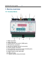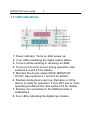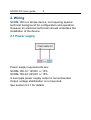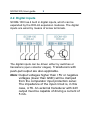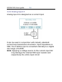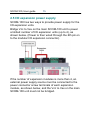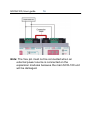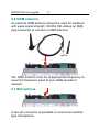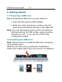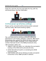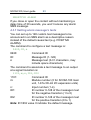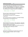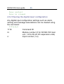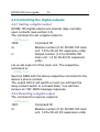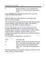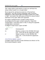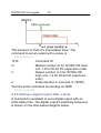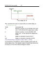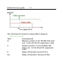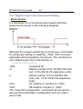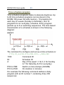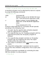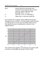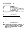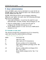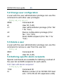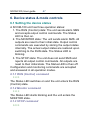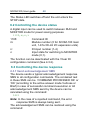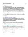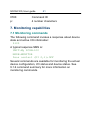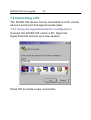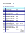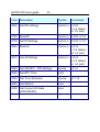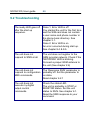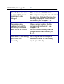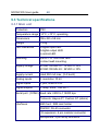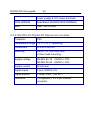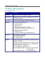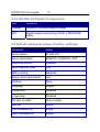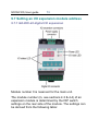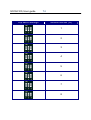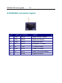
1
SCOM-100, User guide
2
SCOM-100
Alarming & remote control unit
User guide
Manual version: 1.04, 2/2007
Firmware version: 1.04
Disclaimer
While every effort has been made to ensure that the
information included in this guide is accurate and
complete, no liability can be accepted for any errors
or omissions.
Infinite Ltd reserves the right to change the
specifications of the hardware and software
described in this guide at any time without prior
notice.
No part of this guide may be reproduced,
transmitted, stored in fixed or removable media or
translated into any language in any form without the
prior written permission of Infinite Ltd.
Infinite makes no warranties for damages resulting
from device operation, corrupted or lost data, or any
loss caused by malfunction of the hardware or the
software.
Copyright © 2006, 2007 – Infinite Ltd
All rights reserved.
SCOM-100, User guide
3
Contents
1. Device overview
1.1 Connections
1.2 LED indications
2. Wiring
2.1 Power supply
2.2 Digital inputs
2.3 Digital outputs
2.4 Analog inputs
2.4.1 Analog input 1
2.4.2 Analog input 2
2.5 I/O expansion power supply
2.6 GSM antenna
2.7 Microphone
3. Getting started
3.1 Preparing a SIM card
3.2 Installing the SIM card
3.3 First power up & factory settings
4. Device operation
4.1 SMS commands
4.2 Naming the unit
4.3 Configuring a digital input for alarming
4.3.1 Setting alarm message’s texts
4.3.2 Clearing the digital input configuration
4.4 Controlling the digital outputs
4.4.1 Setting a digital output
4.4.2 Resetting a digital output
4.4.3 Configuring a digital output as a closed contact
4.4.4 Pulse digital output
SCOM-100, User guide
4
4.4.5 Setting a digital output after a delay
4.4.6 Resetting a digital output after a delay
4.4.7 Digital output time based scheduling
4.4.8 Clearing the digital output configuration
4.5 Analog signal alarming
4.5.1 Analog input configuration
4.5.2 Setting alarm message’s texts for analog inputs
4.5.3 Clearing the analog input configuration
4.6 Special I/O Functions
4.6.1 ON/OFF and PID control
5. User administration
5.1 Create a new user
5.2 Change user configuration
5.3 Remove a user
5.4 Defining specific alarm recipients
5.4.1 Set a DI alarm recipient
5.4.2 Set an AI alarm recipient
5.4.3 Clear DI alarm recipients
5.4.4 Clear AI alarm recipients
6. Device status & mode controls
6.1 Setting the device status
6.1.1 RUN (Control) command
6.1.2 Monitor command
6.1.3 Stop command
6.2 Controlling the device status
6.3 Setting the device response
6.3.1 Send response SMS
6.3.2 Response format
6.3.3 Merge concurrent alarms
6.4 Setting up a SMS counter
SCOM-100, User guide
5
6.5 Setting date & time
6.6 Setting a GSM PIN
7. Monitoring capabilities
7.1 Monitoring commands
7.2.1 Using the HyperTerminal for configuration
7.2.2 Using the SCOM-100 Configurator for configuration
8. Using the microphone input
9. Appendix
9.1 Command reference
9.1.1 General parameter settings
9.1.2 User configuration
9.1.3 Output control & configuration
9.1.4 Input configuration
9.1.5 I/O Functions
9.1.6 RTC & Time scheduling
9.1.7 Monitoring commands
9.2 Troubleshooting
9.3 Technical specifications
9.4 Error handling
9.5 Status LED indications
9.6 Default parameter values
9.7 Setting an I/O expansion module address
9.7.1 GE-DIO-42 digital I/O expansion
9.8 RS232C connector layout
SCOM-100, User guide
6
1. Device overview
1.1 Connections
1: Start up button
2: SIM cardholder
3: GSM antenna connector (SMA jack)
4. Microphone connector
5: Serial port RS232 (RJ-42 connector)
6: Power supply connector
7: I/O expansion connector (6 pin modular jack)
8: Analog inputs screw terminals
9: Digital inputs screw terminals
10: DIN rail snap
11: Digital outputs screw terminals
SCOM-100, User guide
7
1.2 LED indications
1: Power indicator: Turns on after power up.
2: Four LEDs indicating the digital output states.
3: Turns on while sending or receiving an SMS.
4: Turns on if an error occurs during operation. See
sections 9.4 and 9.5 for details.
5: Monitors the device status (RUN/ MONITOR/
STOP). See sections 6.1 and 9.5 for details.
6. Flashes during device start up. Remains on if the
device is ready for operation. Turns off if one or more
operating conditions fail. See section 9.5 for details.
7. Flashes if a connection to the GSM provider is
established.
8. Four LEDs indicating the digital input states.
SCOM-100, User guide
8
2. Wiring
SCOM-100 is a simple device, not requiring special
technical background for configuration and operation.
However an electrical technician should undertake the
installation of the device.
2.1 Power supply
Power supply requirements are:
SCOM-100-12: 12VDC +/-15%
SCOM-100-24: 24VDC +/-15%
A low ripple power supply output is recommended.
Output voltage stabilization is not required.
See section 9.3.1 for details.
SCOM-100, User guide
9
2.2. Digital inputs
SCOM-100 has 4 built in digital inputs, which can be
expanded by the DIO-42 expansion modules. The digital
inputs are wired by means of screw terminals.
The digital inputs can be driven either by switches or
transistors (open collector stages). Transducers with
push-pull output are also applicable.
Note: Output voltages higher than +5V or negative
voltages (lower than GND) will be clamped
from the comparator input protection zener.
The impedance of the input circuit is, in this
case, 4.7K. An external transducer with 24V
output must be capable of driving a current of
5 mA.
SCOM-100, User guide
10
2.3 Digital outputs
SCOM-100 has 4 built in digital outputs, which can be
expanded by the DIO-42 expansion modules. The digital
outputs are wired by means of screw terminals. Each
output has a normally open contact power relay.
Voltage
Current
Mode
250VAC
10A
AC1
250VAC
1A
AC2,3
150VDC
0.5A
DC
It is recommended to use external power relays to drive
inductive or capacitive loads demanding more than 0.5A.
SCOM-100, User guide
11
2.4 Analog inputs
SCOM-100 has 2 built in analog inputs (AI1, AI2). A1 is
designed for voltage input and A2 for current input.
2.4.1 Analog input 1
Analog input 1 is a voltage input with two wiring options.
Wiring option: A1A
The input voltage range for this wiring option is 0-1VDC.
The input resistance is 2K. The input voltage range is
converted internally to a digital raw range of 0-4095.
The circuit displayed on the left side of the page uses a
monolithic semiconductor sensor (AD592) for
temperature measurement. This sensor acts as a high
impedance temperature dependent current source of
1µA/K. The nominal current output is 298µA at 25°C. The
voltage drop on the analog input resistor (2K) is 496mV
at -25°C and 756mV at 105°C. The SCOM-100 power
supply (Vcc) can be used for the sensor’s excitation.
SCOM-100, User guide
12
The circuit displayed on the center uses an external
shunt resistor (~51.3 Ω) wired parallel to the input in
order to measure current signals (e.g. 0-20/4-20mA).
The circuit displayed on the right side of the page uses
an external resistor (Rx) to measure DC voltage (Vx). Rx
and Rin (2K) form a voltage divider. The following table
illustrates the applicable resistor Rx values for different
DC voltages:
Vx
0..1V
0..5V
0..30V
0..60V
0..100V
Rx
0
8K, 1/4W
58K, 1/4W
118K, 1/4W
198K, 1/4W
Vin
0 -1V
0 -1V
0 -1V
0 -1V
0 -1V
Note: In case of low voltage measurements, use short
and shielded wiring to avoid 50Hz (60Hz) line noise
inteference.
SCOM-100, User guide
13
Wiring option: A1B
Wiring option A1B is designed for 0..10VDC signal input
through an internal 18K & 2K voltage divider. The input
resistance is 20K.
SCOM-100, User guide
14
2.4.2 Analog input 2
Analog input 2 is designed as a current input.
It can be used in conjunction with industry standard
current loop transducers & sensors. Input impedance is
50Ω. The 0-20mA input is converted internally to a digital
raw range of 0-4095.
Note: Applying a voltage source to the current input AI2
may damage the internal 50Ω input resistor and
respectively the entire input circuit.
SCOM-100, User guide
15
2.5 I/O expansion power supply
SCOM-100 has two ways to provide power supply for the
I/O expansion units.
Bridge Vcc to Vex on the main SCOM-100 unit to power
a limited number of I/O expansion units (up to 4), as
shown below. (Power is then wired through the 6th pin on
to the modular I/O expansion connector).
If the number of expansion modules is more than 4, an
external power supply source must be connected to the
power connector screw terminals of each expansion
module, as shown below, and the Vcc to Vex on the main
SCOM-100 unit must not be bridged.
SCOM-100, User guide
16
Note: The Vex pin must not be connected when an
external power source is connected on the
expansion modules because the main SCO-100 unit
will be damaged.
SCOM-100, User guide
17
2.6 GSM antenna
An external GSM antenna should be used for locations
with weak signal strength. SCOM-100 utilizes an SMA
plug connector to connect a GSM antenna.
The GSM antenna must be of appropriate frequency to
cover the frequency band of your GSM provider’s
network.
2.7 Microphone
A two-pin connector is provided to connect an electret
type microphone.
SCOM-100, User guide
18
3. Getting started
3.1 Preparing a SIM card
Before installing the SIM card, use your phone to:
1. Clear the PIN code (no PIN needed).
2. Enter your name and phone number in the first
place of the phonebook directory of the SIM card.
Note: You can alternatively power up the unit without a
SIM card and set the PIN number using a terminal
program on a PC, or you can set a PIN in later
configuration stages.
3.2 Installing the SIM card
Note: Always remove or install the SIM card, having the
unit powered down!
Slide the card tray out by pressing the cardholder’s
button with a spiky object such as a pencil or screwdriver.
SCOM-100, User guide
19
Insert the card into the tray and slide the tray with the
card faced down into the cardholder.
3.3 First power up & factory settings
Power up the unit and hold the startup button pressed
until the ready LED starts blinking rapidly.
The unit executes the startup procedure setting all
parameters to the factory defaults, reads the SIM card’s
phonebook entry, enters the RUN (Control) mode and
sends a HELLO SMS message to the mobile phone
number that was found in the SIM phonebook entry.
LED indication states are:
1. READY LED will switch on indicating the successful
reading of the SIM card’s phonebook entry.
2. STATUS LED will switch on indicating the RUN
(Control) mode.
3. NETWORK LED will be blinking to state successful
connection to the GSM provider’s network.
SCOM-100, User guide
20
4. Device operation
4.1 SMS commands
The SCOM-100 unit accepts text SMS commands to
configure operational parameters, control the unit’s
operation modes, and control the unit’s outputs. Several
commands can be packed in one SMS message.
An SMS command has the following structure:
XXXX,A..A,..,..,Z..Z
XXXX:
Command identification number 00009999
A..A, Z..Z:
Command parameters
The comma character (‘,’) is used as a separator in the
command structure. The semicolon character (‘;’) is used
to separate more than one commands packed in a single
SMS.
4.2 Naming the unit
You can specify a unit name for identification purposes.
The unit name will be used in several device’s SMS
transmissions and responses. The command to name the
unit is:
0300,My SCOM-100
0300:
Command ID
My SCOM-100: Device name
Use your mobile phone to edit an SMS containing the
above command. Type in the characters without any
SCOM-100, User guide
21
spaces between except in text strings (eg. The name ‘My
SCOM-100’ may contain spaces). Send the SMS to the
SCOM-100 mobile phone number of the SIM. You will
receive an SMS with the following response:
COMMAND PROCESSED OK
indicating that the device’s name is configured.
4.3 Configuring a digital input for alarming
A digital input can be configured to initiate an alarm SMS
transmission after a signal change. The following
selections can be made:
1. Give a name to the digital input. This name will be
attached to the alarm SMS if the unit answer mode is
verbose.
2. Configure the signal transition desired to initiate the
alarm SMS by selecting between a positive (0 to 1), a
negative (1 to 0) or any transition.
3. Specifying a delay time for alarm annunciation. The
signal change must persist during this delay period in
order to initiate an alarm SMS.
The DI configuration command structure is:
1100,m,n,s,a,d
1100:
Command ID
m:
Module number (0 for SCOM-100 main
unit, 1-8 for DI-42 I/O expansion units)
n:
Input number (1-4)
SCOM-100, User guide
s:
a:
d:
22
Input signal name (Text: 0-15
characters, may include space
characters)
Transition selection (0: No alarm, 1:
positive 2: negative 3: both transitions)
Delay time in seconds (0-65535)
The following example illustrates how to configure digital
input 1 to initiate an alarm SMS after any signal
transition, a delay time of 30 seconds and a signal name
configured to “Door contact”.
The configuration command would be:
1100,0,1,Door contact,3,30
Send an SMS to the SCOM-100 unit with the respective
command.
Connect a contact or a loop wire to digital input 1
according to the wiring diagram in section 2.2. Close the
contact/loop and leave it closed for more than 30
seconds. The S/R SMS LED will blink and you will
receive an alarm SMS message and the following
contents:
My SCOM-100
Door contact
POSITIVE ALARM
Now open the input contact/loop for 30 seconds. You will
receive an alarm SMS message with the following
contents:
My SCOM-100
Door contact
SCOM-100, User guide
23
NEGATIVE ALARM
If you close or open the contact without maintaining a
delay time of 30 seconds, you won’t receive any alarm
SMS message.
4.3.1 Setting alarm message’s texts
You can set up to 128 custom text messages to be
announced in an SMS alarm as a descriptive reason
instead of the default causal text (e.g. POSITIVE
ALARM).
The command to configure a text message is:
0630,ID,s
0630:
Command ID
ID:
Message ID (1-128)
s:
Message text (0-31 characters, may
include space characters)
The command to associate a text message to an output
at a signal transition is:
1101,m,n,ID1,ID2
1101:
Command ID
m:
Module number (0 for SCOM-100 main
unit, 1-8 for DI-42 I/O expansion units)
n:
Input number (1-4)
ID1:
ID number 0-128 of the message’s text
for the negative transition (1 to 0)
ID2:
ID number 0-128 of the message’s text
for the positive transition (0 to 1)
Note: ID1/ID2 value 0 indicate the default message.
SCOM-100, User guide
24
Let us specify alarm text messages for the previous
example. The message for the positive (0 to 1) transition
should be ‘Door is opened’. The respective message for
the negative transition should be ‘Door is closed’.
The commands to configure these text messages are:
0630,1,Door is opened;
0630,2,Door is closed
Now we have to associate the text messages to the
signal transitions of the example.
The respective command for our example is:
1101,0,1,2,1
We can pack all three commands in one SMS message
and send them to the SCOM-100 unit:
0630,1,Door is opened;
0630,2,Door is closed;
1101,0,1,2,1
After sending and receiving an ‘OK’ response, repeat the
signal changes by closing the contact/loop for at least 30
seconds and then open it again.
Closing of the input for at least 30 seconds will issue an
alarm SMS with the following contents:
My SCOM-100
Door contact
Door is opened
Opening the contact/loop for at least 30 seconds will
issue the negative transition alarm message:
My SCOM-100
SCOM-100, User guide
25
Door contact
Door is closed
4.3.2 Clearing the digital input configuration
Any digital input configuration settings such as alarm,
naming and message associations can be cleared using
the command:
1110,m,n
1110:
Command ID
m:
Module number (0 for SCOM-100 main
unit, 1-8 for DI-42 I/O expansion units)
n:
Input number (1-4)
SCOM-100, User guide
26
4.4 Controlling the digital outputs
4.4.1 Setting a digital output
SCOM-100 digital outputs are internal relay normally
open contacts (see section 2.3).
The command to set a digital output is:
1000,m,n
1000:
Command ID
m:
Module number (0 for SCOM-100 main
unit, 1-8 for DI-42 I/O expansion units)
n:
Output number (1-4 for SCOM-100
main unit, 1-2 for DI-42 I/O expansion
units)
Let us set output 2 of the main unit. The respective
command is:
1000,0,2
Send an SMS with the above respective command to the
device’s phone number.
The output LED 2 will switch on and you will hear the
relay contact switch to a closed state. You will then
receive an “OK’ SMS message response.
4.4.2 Resetting a digital output
The command to reset an output is:
1001,m,n
1001:
Command ID
m:
Module number (0 for SCOM-100 main
unit, 1-8 for DI-42 I/O expansion units)
SCOM-100, User guide
n:
27
Output number (1-4 for SCOM-100
main unit, 1-2 for DI-42 I/O expansion
units)
In our example the respective command to reset the
output 2 of the main unit is:
1001,0,2
Send an SMS with the respective command to the
device’s phone number.
The output LED will switch off and you will hear the relay
contact switch to the initial open state. You will then
receive an “OK’ SMS message response.
4.4.3 Configuring an output as a closed contact
SCOM-100 digital outputs, as mentioned above, are
normally open contacts. In some cases an initial closed
contact state is required. In those cases, you can
configure the respective output to be a closed contact in
its initial state.
The respective configuration command is:
1071,m,n
1071:
Command ID
m:
Module number (0 for SCOM-100 main
unit, 1-8 for DI-42 I/O expansion units)
n:
Output number (1-4 for SCOM-100
main unit, 1-2 for DI-42 I/O expansion
units)
Send the following command to configure output 2 of the
main unit as a closed contact:
1071,0,2
SCOM-100, User guide
28
The output LED 2 will switch on and you will hear the
relay contact switch to a closed state.
Now repeat the set/reset procedure of the last two
examples. You will receive messages with a reverse
behaviour of the output LED and relay contact. E.g. after
a ‘SET’ command, the LED goes off and the relay contact
switches to the open state and opposite.
An output configured as a closed contact can be
reconfigured to an open contact using the ‘Clear DO
configuration’ command (see 4.4.8) or using the opposite
configuration command.
Configure output as an open contact:
1070,m,n
1071:
Command ID
m:
Module number (0 for SCOM-100 main
unit, 1-8 for DI-42 I/O expansion units)
n:
Output number (1-4 for SCOM-100
main unit, 1-2 for DI-42 I/O expansion
units)
4.4.4 Pulse digital output
A digital output set with a pulse behaves as shown on the
time-based diagram below.
SCOM-100, User guide
29
This behavior is that of a monostable timer. The
command to set an output with a pulse is:
1010,m,n,s
1010:
Command ID
m:
Module number (0 for SCOM-100 main
unit, 1-8 for DI-42 I/O expansion units)
n:
Output number (1-4 for SCOM-100
main unit, 1-2 for DI-42 I/O expansion
units)
s:
Pulse duration in seconds (1-79200)
Test the pulse command by sending an SMS:
1010,0,2,25
4.4.5 Setting a digital output after a delay
A command is available to set a digital output with an
initial delay time. The digital output’s switching behaviour
is shown on the time-based diagram below.
SCOM-100, User guide
30
The command to set an output after an initial delay is:
1020,m,n,h,mn
1020:
Command ID
m:
Module number (0 for SCOM-100 main
unit, 1-8 for DI-42 I/O expansion units)
n:
Output number (1-4 for SCOM-100
main unit, 1-2 for DI-42 I/O expansion
units)
h:
Delay on duration hours (0-21)
mn:
Delay on duration minutes (0-59)
4.4.6 Resetting a digital output after a delay
A command is available to reset a digital output with an
initial delay time. The digital output’s switching behaviour
is shown on the time-based diagram below.
SCOM-100, User guide
31
The command to reset an output after a delay is:
1021,m,n,h,mn
1021:
Command ID
m:
Module number (0 for SCOM-100 main
unit, 1-8 for DI-42 I/O expansion units)
n:
Output number (1-4 for SCOM-100
main unit, 1-2 for DI-42 I/O expansion
units)
h:
Delay off duration hours (0-21)
mn:
Delay off duration minutes (0-59)
SCOM-100, User guide
32
4.4.7 Digital output time based scheduling
Multivibrator
A multivibrator is a continuous time based switching
sequence as shown in the following diagram:
Although the output’s switching is continuous, commands
for temporary setting or resetting (1000, 1001) are also
applicable and accepted by the device. The command to
set a digital output as a multivibrator is:
1040,m,n,mon,moff
1040:
Command ID
m:
Module number (0 for SCOM-100 main
unit, 1-8 for DI-42 I/O expansion units)
n:
Output number (1-4 for SCOM-100
main unit, 1-2 for DI-42 I/O expansion
units)
mon:
On duration in minutes (1-1320)
moff:
Off duration minutes (1-1320)
The ‘Clear DO configuration’ command can be used to
remove the multivibrator configuration from an output
(see 4.4.8).
SCOM-100, User guide
33
Time schedule program
Time schedule programs relate to absolute daytimes. Up
to 80 time schedule programs can be stored in the
SCOM-100 power fail safe memory, 10 programs for
each day of a week (Sunday to Saturday), and 10
programs for an ‘everyday’ schedule. Every program
permits up to 8 on switching sequences. The time based
characteristic of a schedule is shown in the following
diagram:
The command to configure and set up a time schedule is:
1700,ID,d,P1B-P1D,P2B-P2D,…,P8B-P8D
1700:
Command ID
ID:
Schedule ID
d:
Day of the week 1-7 & 0 (1 for Sunday
to 7 for Saturday & 0 for everyday)
P1B to P8B:
Switch on time stamps (HH:MM)
P1D to P8D:
On duration in minutes
For example the following command defines a daily
program with an ID number 1 containing three ON
sequences:
SCOM-100, User guide
34
1700,1,0,8:00-120,11:30-100;16:45-180
A schedule program can be attached the device’s outputs
by using the following command:
1030,m,n,ID
1030:
Command ID
m:
Module number (0 for SCOM-100 main
unit, 1-8 for DI-42 I/O expansion units)
n:
Output number (1-4 for SCOM-100
main unit, 1-2 for DI-42 I/O expansion
units)
ID:
Time schedule ID (1-10)
A device output attached on a schedule ID will operate
according to the following rules:
1. On each day the specific daily schedule program
with the respective ID is followed.
2. If no specific day (e.g. for Tuesday) program with the
respective ID exists, the ‘Everyday’ program is
followed.
3. If no specific day program and also no ‘Everyday’
program with the respective ID exist, the output
remains off for the whole day.
4. The output is activated at the next switch on time
stamp.
The ‘Clear DO configuration’ command can be used to
remove the time schedule configuration of an output (see
4.4.8).
A special command is available for controlling the total
ON time duration in a day program:
1701,ID,P
SCOM-100, User guide
1701:
P:
35
Command ID
Factor in % (0-100%). The ON duration
of each program sequence is
calculated by multiplicating this factor
with the initial sequence duration.
Example:
Reducing the total ON duration of program 3 to the half:
1701,3,50
4.4.8 Clearing the digital output configuration
The command clears any output configurations related
with multivibrator or time schedules:
1090,m,n,ID
1090:
Command ID
m:
Module number (0 for SCOM-100 main
unit, 1-8 for DI-42 I/O expansion units)
n:
Output number (1-4 for SCOM-100
main unit, 1-2 for DI-42 I/O expansion
units)
SCOM-100, User guide
36
4.5 Analog signal alarming
4.5.1 Analog input configuration
The SCOM-100 analog inputs can be configured to
initiate alarm SMS messages when preset alarm limit
conditions (low & high alarm limits) are met. A user
configurable scale can be defined to associate an analog
input signal to physical units. The configuration command
is:
1200,m,n,s,SSL,SSH,SCL,SCH,ALL,ALH,u,d
1200:
Command ID
m:
Module number (0 for SCOM-100 main
unit, 1-4 for AI-4 expansion units)
n:
Input number (1-2 for SCOM-100 main
unit, 1-4 for AI-4 expansion units)
s:
Input signal name (Text: 0-15
characters, may include space
characters)
SSL:
Raw value reading for scale low (04095)
SSH:
Raw value reading for scale high (04095)
SCL:
Scale low in physical units (-100,000 to
100,000)
SCH:
Scale high in physical units (-100,000
to 100,000)
ALL:
Alarm low limit in physical units
(Number in the range of SCL to SCH
with one optional decimal digit.
Example: ALL = 52.3)
SCOM-100, User guide
ALH:
u:
d:
37
Alarm high limit in physical units
(number in the range of SCL to SCH
with one optional decimal digit.
Example: ALH = 121.5)
Physical unit (0-15 characters)
Delay time in seconds (0-65535)
For example let us explain all the different parameter
settings to use a 4-20mA, 0-10 bar pressure sensor wired
on analog input 2 on the main unit (See section 2.4.2).
The pressure sensor characteristic is shown in the
diagram below:
The 4-20mA input signal is converted by the internal A/D
converter in the digital raw range of 819 to 4095.
SCOM-100, User guide
38
The following diagram illustrates the conversion
characteristic:
The conversion values are given by the formula:
Raw digital value:=4095 * Ix/20
Ix: Input current value (mA)
According to the formula, a 4mA input is converted to:
Raw digital value=4095*4/20 = 819
This is the value setting for SSL.
A 20mA input is converted to a raw reading of 4095.
This is the value setting for SSH.
SCOM-100 physical scale values are limited to integer
values between -100,000 and 100,000. It is reasonable to
select the physical scale in the range of 0 to 10,000 mBar
to gain a better resolution.
The configuration command would then be:
SCOM-100, User guide
39
1200,0,2,Pressure,819,4095,0,10000,2500,
8500,mBar,15
The low alarm limit is set to 2.5 Bar, the high alarm limit
to 9.5 Bar. A 15 second delay is also set so that the input
signal must persist in value and exceed alarm limits (low
or high) for 15 seconds. If these clauses are met then an
alarm SMS will be initiated.
Note: Alarm annunciation is cancelled if the respective
Scale (low or high) and limit alarm values (low or
high) are equal.
4.5.2 Setting alarm message’s texts for analog inputs
A similar command to the one for digital inputs is
available to associate low and high alarm events with
respective SMS messages (1-128 messages, see 4.3.1).
The configuration command is:
1201,m,n,ID1,ID2
1201:
Command ID
m:
Module number (0 for SCOM-100 main
unit, 1-4 for AI-4 expansion units)
n:
Input number (1-2 for SCOM-100 main
unit, 1-4 for AI-4 expansion units)
ID1:
ID number 0-128 of the message’s text
for exceeding the low limit
ID2:
ID number 0-128 of the message’s text
for exceeding the high limit
Note: ID1/ID2 value 0 means no message.
SCOM-100, User guide
40
4.5.3 Clearing the analog input configuration
Any analog input configuration settings such as alarm,
naming, messaging and scaling can be cleared using the
command:
1210,m,n
1210:
Command ID
m:
Module number (0 for SCOM-100 main
unit, 1-4 for AI-4 expansion units)
n:
Input number (1-2 for SCOM-100 main
unit, 1-4 for AI-4 expansion units)
4.5.4 Setting the analog inputs alarm deadband
A special command is available to configure alarm
deadband (hysteresis) for all analog inputs. Alarm
deadband is a small range in the total scale of the input
signal where alarm states remain indifferent, holding on
their last value - in order to avoid frequent SMS
transmissions.
The Alarm deadband is given as a percent of the total
scale.
1800,d
1800:
Command ID
d:
Alarm deadband value in % up to 5% of
the total scale (0-5% in 0.1 steps).
Example: d =2.3%
SCOM-100, User guide
41
4.6 Special I/O Functions
4.6.1 ON/OFF and PID control
Up to four ON/OFF or PID control function blocks are
available. Each block uses an analog input for measuring
the process value and a digital output for control.
Function block configuration
1250,id,m,n,m1,n1,sp,g,it,dt,ct,h
1250:
Command ID.
id:
Function block ID (1-4).
m:
Module number (0 for SCOM-100 main
unit, 1-4 for AI-4 expansion units).
n:
Input number (1-2 for SCOM-100 main
unit, 1-4 for AI-4 expansion units).
m1:
Module number (0 for SCOM-100 main
unit, 1-8 for DI-42 I/O expansion units).
n1:
Output number (1-4 for SCOM-100
main unit, 1-2 for DI-42 I/O expansion
units).
sp:
Set point value in the range of the
analog input scale.
g:
‘Gain’ value (P) between 1 and 100%.
The block function depends on the
‘Gain’ value: A zero value selects the
ON/OFF control function. A non zero
value selects the PID function.
it:
‘Integral time’ (I) value between 1-1000
sec. A zero value disables the integral
part (not relevant for ON/OFF control).
SCOM-100, User guide
dt:
42
‘Derivative time’ (D) value between 1200 sec. A zero value disables the
drivative part (not relevant for ON/OFF
control)..
ct:
‘Cycle time’ value between 1 and 15
minutes, representing the pulse width
modulation period of the digital output
(not relevant for ON/OFF control).
h:
‘Hysteresis’ value in [%] of the analog
input scale (0-20%) for ON/OFF control
(not relevant for PID control).
Changing the set point value
1255,id,sp
1255:
Command ID.
id:
Function block ID (1-4).
sp:
Set point value in the range of the
analog input scale.
Setting the Function block state
The ON/OFF or PID control function block can be
enabled or disabled with this SMS command:
1251,id,s
1251:
Command ID.
id:
Function block ID (1-4).
s:
1: enable, 0:disable
Controlling the Function block state
A digital input can be configured to control the
Enabled/Disabled status of the function block.
The following command selects the digital input.
SCOM-100, User guide
43
1252,id,m,n
1252:
Command ID.
id:
Function block ID (1-4).
m:
Module number (0 for SCOM-100 main
unit, 1-8 for DI-42 I/O expansion units)
n:
DI input number (1-4)
The following command clears the digital input function.
1253,id
1253:
Command ID.
id:
Function block ID (1-4).
Clearing the Function block configuration
The command erases the function block configuration
and frees the function block instance and the respective
I/O.
1260,id
1260:
Command ID.
id:
Function block ID (1-4).
Note: Analog or digital inputs involved in ON/OFF or PID
control function blocks can be used for alarming,
while involved digital outputs are dedicated to
control and cannot be remotely controlled through
SMS commands.
SCOM-100, User guide
44
5. User administration
Up to 20 SMS users can be declared in a user list for an
SCOM-100 unit. Only declared users can interact (send,
receive SMS) with the unit.
SCOM-100 features three user privileges reflecting
different user rights. For each user the following privilege
flag can be configured:
1. User administration. A user has the right for user
administration (Create, Delete, Set privileges) or not.
2. Device configuration. A user has the right to
configure the SCOM-100 device or not.
3. Alarm SMS recipient. A user can be an SMS alarm
recipient or not.
5.1 Create a new user
The device accepts the command only if it is issued by
users who have the administration privilege.
0500,id,n,p,c1,c2,c3
0500:
Command ID
id:
User ID (1-20)
n:
User name (0-15 characters)
p:
Phone number (3-15 characters)
c1:
User administration privilege (0 for ‘No’
1 for ‘Yes’)
c2:
Device configuration privilege (0 for
‘No’ 1 for ‘Yes’)
c3:
Alarm SMS recipient (0 for ‘No’ 1 for
‘Yes’)
SCOM-100, User guide
45
5.2 Change user configuration
A user with the user administration privilege can use this
command to edit other user privileges.
0502,id,c1,c2,c3
0502:
Command ID
id:
User ID (1-20)
c1:
User administration privilege (0 for ‘No’
1 for ‘Yes’)
c2:
Device configuration privilege (0 for
‘No’ 1 for ‘Yes’)
c3:
Alarm SMS recipient (0 for ‘No’ 1 for
‘Yes’)
5.3 Delete a user
A user with the user administration privilege can use this
command to remove a user from the user list.
0501,id
0501:
Command ID
id:
User ID (1-20)
5.4 Defining specific alarm recipients
Special commands are available for defining a subset of
the user list as SMS recipients for each alarm.
5.4.1 Set a DI alarm recipient
1102,m,n,id
1102:
Command ID
m:
Module number (0 for SCOM-100 main
unit, 1-8 for DI-42 I/O expansion units)
SCOM-100, User guide
46
n:
DI input number (1-4)
id:
User ID (1-20)
5.4.2 Set an AI alarm recipient
1202,m,n,id
1202:
Command ID
m:
Module number (0 for SCOM-100 main
unit, 1-4 for AI-4 expansion units)
n:
AI input number (1-2 for SCOM-100
main unit, 1-4 for AI-4 expansion units)
id:
User ID (1-20)
5.4.3 Clear DI alarm recipients
The command removes all recipients for a specific DI
alarm.
1109,m,n
1109:
Command ID
m:
Module number (0 for SCOM-100 main
unit, 1-8 for DI-42 I/O expansion units)
n:
DI input number (1-4)
5.4.4 Clear AI alarm recipients
The command removes all recipients for a specific AI
alarm.
1209,m,n
1209:
Command ID
m:
Module number (0 for SCOM-100 main
unit, 1-4 for AI-4 expansion units)
n:
AI input number (1-2 for SCOM-100
main unit, 1-4 for AI-4 expansion units)
SCOM-100, User guide
47
6. Device status & mode controls
6.1 Setting the device status
A SCOM-100 unit has three operation states:
1. The RUN (Control) state: The unit sends alarm SMS
and accepts output control commands. The Status
LED is then on.
2. The MONITOR state: The unit sends alarm SMS. All
outputs are reset to their initial state. Output control
commands are executed by storing the output states
internally. The actual output states are restored upon
switching to the RUN state. The Status LED is
blinking.
3. The STOP state: The unit does not send SMS and
rejects all output control commands. All outputs are
reset to their initial state. The Status LED is then off.
Configuration and monitoring commands are accepted
and answered in all operation modes.
6.1.1 RUN (Control) command
0100
The Status LED switches on and the unit enters the RUN
(Control) state.
6.1.2 Monitor command
0110
The Status LED starts blinking and the unit enters the
MONITOR state.
6.1.3 STOP command
0000
SCOM-100, User guide
48
The Status LED switches off and the unit enters the
STOP state.
6.2 Controlling the device status
A digital input can be used to switch between RUN and
MONITOR mode for power saving purposes.
1105,m,n,v
1105:
Command ID
m:
Module number (0 for SCOM-100 main
unit, 1-8 for DI-42 I/O expansion units)
n:
DI input number (1-4)
v:
Input state for switching to MONITOR
mode (0,1).
The function can be deactivated with the ‘Clear DI
configuration command (See 4.3.2).
6.3 Controlling the device response
6.3.1 Send acknowledgement SMS
The device sends a typical acknowledgement response
SMS to all configuration commands. The contained text
in these SMS can be ‘COMMAND PROCESSED OK’ or
‘OK’ (according to the active answer mode Verbose or
Brief) in case of successful command execution or All
acknowledgement SMS send by the device can be
cancelled using the command:
0621
Note: In the case of a rejected command, the error
response SMS is always being sent.
The acknowledgement SMS can be restored using the
command:
SCOM-100, User guide
49
0620
6.3.2 Response format
The device acknowledgement SMS can be in verbose or
brief format. The verbose format is informative text and is
recommended for man to machine applications. Brief
format is a briefly coded format for use in machine-tomachine applications. Verbose acknowledgement can be
cancelled using the command:
0611
The verbose acknowledgement can be restored using the
command:
0610
6.3.3 Merge concurrent alarms
The device can send a separate SMS for each alarm or
merge concurrent alarms in one SMS. Alarm merging can
be applied using by the command:
0660
Alarm unmerging can be applied using the command:
0661
6.4 Setting up an SMS counter
An SMS counter can be activated for counting down
available SMS transmissions. A preset limit can be set for
user alarming when the limit is reached.
The counter can be set to a number of remaining SMS
messages using command:.
0650,v
0650:
Command ID
SCOM-100, User guide
50
v:
Remaining SMS number (04294967295)
Remaining SMS messages limit reach will be
acknowledged to users if a limit is set using command:
0600,l
0600:
Command ID
l:
Remaining SMS alarm limit (04294967295)
Remaining SMS alarm annunciation can be cancelled
using the command:
0601
6.5 Setting date and time
The device real time clock (RTC) can be set through the
following command:
1600,d,m,y,h,m,s
1600:
Command ID
d:
Day of the month (1-31)
m:
Month of the year (1-12)
y:
Year
h:
Hour
m:
Minutes
s
Seconds
6.6 Setting a GSM PIN
An optional SIM card PIN can be set through the
following command:
0783,p
SCOM-100, User guide
0783:
p:
51
Command ID
4 number characters
7. Monitoring capabilities
7.1 Monitoring commands
The following command invokes a response about device
state and active I/O information:
5100
A typical response SMS is:
UNIT:My SCOM-100
MODE:MONITOR
Door contact (DI 0,1):OFF
Several commands are available for monitoring the actual
device configuration, I/O status and device status. See
9.1.6 command summary for more information on
monitoring commands.
SCOM-100, User guide
52
7.2 Connecting a PC
The SCOM-100 device can be connected to a PC via the
device’s serial port and special serial cable.
7.2.1 Using the Hyperterminal for configuration
Connect the SCOM-100 unit to a PC. Open the
HyperTerminal and set up a new session.
Press OK to create a new connection.
SCOM-100, User guide
53
Select a serial connection, choose the appropriate serial
port and press ‘OK’. Select the following settings for the
serial port:
SCOM-100, User guide
54
Open the ‘Properties’ menu and press the ‘ASCII Set up’
button.
Check the option ‘Append line feeds to incoming line
ends’ and press ‘OK’ to leave the Properties dialog.
Type in:
at
and press <ENTER>.
SCOM-100, User guide
55
If a connection is established the answer is ‘OK’. If you
don’t see your typed characters, give the following
command to enable character echoing:
Ate1
All configuration commands can be passed to the unit
from the Windows HyperTerminal. The command
structure is the same to that of the SMS commands,
except the fact that they are embedded in an overall
‘atsms’ command.
Example:
The SMS command:
1100,0,1,Door contact,3,30
for digital input configuration can be given via the terminal
as:
atsms=”1100,0,1,Door contact,3,30”
All device responses are routed to the terminal’s screen.
7.2.2 Using the SCOM Configurator for configuration
The SCOM Configurator is a Windows application for
convenient configuring and commissioning the SCOM100 unit. See the SCOM Configurator’s manual for more
information.
SCOM-100, User guide
56
8. Using the microphone input
A microphone input is provided for the temporary auditive
room observation in a remote SCOM-100 site installation.
An electret microphone must be connected to the
respective input for using this option.
SCOM-100 answers incoming voice calls from users with
the administration priviledge. All remote control and
alarming capabilities are temporary suspended during
the auditive session. Any occuring alarms are
transmitted after the session termination.
The auditive session is terminated automatically after 10
minutes by the SCOM GSM modem or can be anytime
terminated by a user hang up.
SCOM-100, User guide
57
9. Appendix
9.1 Command reference
9.1.1 General parameter settings
Cmd
Description
Syntax
Comments
0000
Set Unit Mode:
Stop
cmd
0100
Set Unit Mode:
Control
cmd
0110
Set Unit Mode:
Monitor
cmd
0150
Get Last Error
Report
cmd
0171
Reset Device
cmd
0183
Set Factory
Defaults
cmd,cm
d
0200
Clear Error Led
cmd
0300
Set Device Name
cmd,s
s:0-15
0310
Set Device
Description
cmd,s
s:0-60
0600
Set Remaining
SMS Alarm Limit
cmd,l
l:0-4294967295
0601
Cancel Remaining
SMS Alarm
cmd
0610
Set Verbose
Responses
cmd
SCOM-100, User guide
58
Cmd
Description
Syntax
0611
Cancel Verbose
Responses
cmd
0620
Set
acknowledgement
SMS
cmd
0621
Cancel
acknowledgement
SMS
cmd
0630
Set Alarm
Message Text
cmd,id,s id:1-128, s:0-31
0650
Set Remaining
SMS Counter
cmd,v
0660
Merge Concurrent
Alarms
cmd
0661
Unmerge
cmd
Concurrent Alarms
0783
Set GSM PIN
cmd,p
Comments
v:0-4294967295
p:4
SCOM-100, User guide
59
9.1.2 User configuration
Cmd
Description
Syntax
Comments
Id:1-20, n:0-15,
p:3-15,
c1-c3: 0-1
(config users, config
device, receive alarm
SMS)
0500
Create User
cmd,id,n,p,
c1,c2,c3
0501
Delete User
cmd,id
0502
Set User
cmd,id,c1,c id:1-20,
Configuration 2,c3
c1-c3: 0-1
(config users, config
device, receive alarm
SMS)
1102
Set DI Alarm
Recipient
cmd,m,n,id
m:0-8, n:1-4, id:1-20
1202
Set AI Alarm
Recipient
cmd,m,n,id
m:0-4, n:1-2 (base) or 1-4
(ext), id:1-20
1109
Clear DI
Alarm
Recipients
cmd,m,n
m:0-8, n:1-4
1209
Clear AI
Alarm
Recipients
cmd,m,n
m:0-4, n:1-2 (base) or 1-4
(ext)
id:1-20
SCOM-100, User guide
60
9.1.3 Output control & configuration
Cmd
Description
Syntax
Comments
1000
Set DO
cmd,m,n
m:0-8, n:1-4 (base)
or 1-2 (ext)
1001
Reset DO
cmd,m,n
m:0-8, n:1-4 (base)
or 1-2 (ext)
1010
Pulse DO
cmd,m,n,s
m:0-8, n:1-4 (base)
or 1-2 (ext), s:1-79200
seconds
1020
Set DO After
Delay
cmd,m,n,h,mn m:0-8, n:1-4 (base)
or 1-2 (ext),
h:0-21 hours,
mn:0-59 minutes
1021
Reset DO
After Delay
cmd,m,n,h,mn m:0-8, n:1-4 (base)
or 1-2 (ext),
h:0-21 hours,
mn:0-59 minutes
1030
Attach DO to cmd,m,n,id
Time
Schedule
1040
Set DO as
Multivibrator
cmd,m,n,mon, m:0-8, n:1-4 (base)
moff
or 1-2 (ext),
mon:1-1320 minutes,
moff:1-1320 minutes
1050
Set DO
Name
cmd,m,n,s
m:0-8, n:1-4 (base)
or 1-2 (ext), id:1-10
m:0-8, n:1-4 (base)
or 1-2 (ext), s:0-15
SCOM-100, User guide
61
Cmd
Description
Syntax
Comments
1070
Init DO as
Open
Contact
cmd,m,n
m:0-8, n:1-4 (base)
or 1-2 (ext)
1071
Init DO as
Closed
Contact
cmd,m,n
m:0-8, n:1-4 (base)
or 1-2 (ext)
1090
Clear DO
cmd,m,n
Configuration
m:0-8, n:1-4 (base)
or 1-2 (ext)
9.1.4 Input configuration
Cmd
Description
Syntax
Comments
1100 Set DI
Configuration
cmd,m,n,s,a,d
m:0-8, n:1-4, s:0-15,
a:0-3, d:0-65535
1101 Set DI Alarm
Messages
cmd,m,n,id1,id2
m:0-8, n:1-4,
id1/id2:0-128
1110 Clear DI
Configuration
cmd,m,n
m:0-8, n:1-4
1200 Set AI
Configuration
cmd,m,n,s,ssl,ss m:0-4, n:1-2 (base)
h,scl,sch,all,alh, or 1-4 (ext), s:0-15,
u,d
ssl/ssh:0-4095
scl/sch/all/alh:
-100000…100000,
u:0-15, d:0-65535
SCOM-100, User guide
Cmd
Description
62
Syntax
Comments
1201 Set AI Alarm
Messages
cmd,m,n,id1,id2
m:0-4, n:1-2 (base)
or 1-4 (ext),
id1/id2:0-128
1210 Clear AI
Configuration
cmd,m,n
m:0-4, n:1-2 (base)
or 1-4 (ext)
1800 Set analog IN
deadband
Cmd,d
D:0-5% of the total
scale with 0.1 steps
9.1.5 I/O Functions
Cmd
Description
Syntax
Comments
1250
Set ON/OFF cmd,id,m,n,m id:1-4, m,n:AI,
- PID Control 1,n1,sp,g,it,dt, m1,n1:DO,
Configuration ct,h
sp:-100000-100000,
g:0.0-100.0,
it:0-1000 sec,
dt:0-200 sec,
ct:1-15 min,
h:0.0-20.0 %
1251
Set ON/OFF cmd,id,s
- PID Control
state
id:1-4, s:0-1
1252
Set PID
Control DI
cmd,id,m,n
id:1-4, m:0-8, n:1-4
1253
Clear PID
Control DI
cmd,id
id:1-4
SCOM-100, User guide
63
Cmd
Description
Syntax
Comments
1255
Set PID
Control Set
Point
cmd,id,sp
id:1-4, sp:-100000100000
1260
Clear PID
cmd,id
Control
Configuration
id:1-4
1105
Set DI for
device
Status
control
m:0-8, n:1-4, v:0-1
cmd,m,n,v
9.1.6 RTC & Time scheduling
Cmd
Description
Syntax
Comments
1600 Set RTC Time
cmd,d,m,y,h,m,
s
d: Day of month (131), m: Month of
year (1-12), y:Year,
h:Hour, m:Minutes,
s:Seconds
1700 Set Time
Schedule Day
cmd,id,d,
p1b-p1d,
p2b-p2d,…,
p8b-p8d
id:1-10,
d:1-7
(1:Sun, 2:Mon, etc)
1701 Set Time
Schedule
Duration Percent
cmd,id,p
id:1-10, p:0-100
1710 Clear Time
Schedule
cmd,id
id:1-10
SCOM-100, User guide
64
9.1.7 Monitoring commands
Cmd
Description
Syntax
Comments
2000 Get Device Status
cmd
2006 Get Device Software Version
cmd
2300 Get Device Name
cmd
2310 Get Device Description
cmd
2500 Get User Info
cmd
2600 Get Remaining SMS Alarm
Limit
cmd
2601 Get Remaining SMS Alarm
Status
cmd
2610 Get Verbose Responses
cmd
2620 Get Acknowledge Status
cmd
2630 Get Alarm Message Text
cmd,id
2650 Get Remaining SMS Counter
cmd
2660 Get Alarm Merge Status
cmd
2710 Get Available Alarm Message
ID
cmd
3000 Read DO
cmd,m,n m:0-8,
n:1-4 (base)
or 1-2 (ext)
id:1-128
SCOM-100, User guide
Cmd
65
Description
Syntax
Comments
3050 Get DO settings
cmd,m,n m:0-8,
n:1-4 (base)
or 1-2 (ext)
3100 Read DI
cmd,m,n m:0-8, n:1-4
3110 Get DI Settings
cmd,m,n m:0-8, n:1-4
3200 Read AI
cmd,m,n m:0-4,
n:1-2 (base)
or 1-4 (ext)
3210 Get AI Settings
cmd,m,n m:0-4,
n:1-2 (base)
or 1-4 (ext)
3250 Get ON/OFF - PID Settings
cmd,id
3600 Get RTC Time
cmd
3700 Get Time Schedule
cmd,id
5000 Get HELLO
cmd
5100 Get Current IO State
(AI/DI/AO/DO)
cmd
id:1-4
id:1-10
SCOM-100, User guide
66
9.2 Troubleshooting
The ready LED goes off
after the start up
sequence.
Case 1: Error LED is off
You started the unit for the first time
and the SIM card does not contain
a user name and phone number in
the phone book directory. See
chapter 3.1.
Case 2: Error LED is on
An error occurred during start up.
See chapter 9.4 & 9.5.
The unit does not
respond to SMS at all.
The unit does not register to the
GSM provider network. Check if the
‘NETWORK’ LED is blinking.
Connect a proper GSM antenna to
the unit (See chapter 2.6)
The unit does not
respond to configuration
SMS commands.
The ‘Response SMS’ parameter is
probably off. Set the parameter to
on state.
Read chapter 6.2.1
The unit does not
execute my digital
output control
commands.
Check the status LED.
The unit is probably in STOP or
MONITOR status. Set the unit
status to RUN. See chapter 6.1.
Read the SMS response to your
command.
SCOM-100, User guide
67
The unit does not send
an alarm SMS after a
digital input state
changes.
The device is in STOP mode.
The respective input is not activated
for alarming. Activate the input by
sending the proper configuration
command (See chapter 4.3).
The analog value
readings through the
monitoring command
seem not to be correct.
Check sensor cabling for the
corresponding channel (see
chapter 2.4)
Set the correct analog channel
measurement parameters (see
4.5.1).
Alarm SMS of an analog Set a higher alarm delay or a
input come too
deadband value for the analog
frequently.
inputs (see 4.5.4)
SCOM-100, User guide
68
9.3 Technical specifications
9.3.1 Main unit
Protection
IP20
Temperature range -10°C, +70°C, operating
Dimensions
106 x 90 x 58 mm
Weight
0.3 kg
LED indications
4 digital input LED
4 digital output LED
6 control LED
Mounting
EN 60 715 TH35 DIN rails
or direct wall mounting.
Supply voltage
SCOM-100-MU-12 : 12VDC+/-10%
SCOM-100-MU-24 : 24VDC+/-10%
Supply current
rated 250 mA max, (2 A burst)
Analog inputs
2, resolution 10 bit
Digital inputs
4, pull, GND to Vcc
Digital outputs
4, relay, 250V, 10A AC1
Serial port (COM2) Baud rate: 2400 to 115200 bps
Protocols: Hayes AT, Custom AT (atsms)
Interfaces
SIM Card : SIM card holder
RS232C: RJ-45 connector
I/O expansion: 6 pin modular connector
Microphone: 2 pin array connector
SCOM-100, User guide
69
Power supply & I/O: screw terminals
GSM MODEM
Quad Band (850/900/1800/1900MHz)
SMS
GSM Text Format
9.3.2 GE-DIO-42 Digital I/O Expansion module
Protection
IP20
Temperature range -10°C, +70°C, operating
Dimensions
53 x 90 x 58 mm
Mounting
EN 60 715 TH35 DIN rails
or direct wall mounting.
Supply voltage
GE-DIO-42-12 : 12VDC+/-10%
GE-DIO-42-24 : 24VDC+/-10%
Supply current
80 mA max
Digital inputs
4, pull, GND to Vcc
Digital outputs
2, relay, 250V, 10A AC1
Interfaces
I/O expansion: 2 x 6 pin modular
connector
SCOM-100, User guide
9.4 Error handling
70
SCOM-100, User guide
71
9.5 Status LED indications
9.5.1 Main unit
LED
Indication
POWER
Presence of power supply voltage
NETWORK
Blinking upon successful registration the GSM
provider’s network
S/R SMS
Turns on during SMS receive or transmit
ERROR
• Turns on after start up:
SIM card error
Modem error
Missing I/O expansion module
Excessive EM noise or hardware error
• Turns on during operation
Modem error
Excessive EM noise or hardware error
STATUS
ON: RUN (Control) state
Blink: MONITOR state
OFF: STOP state
READY
Blinking slowly: The unit starts up after power up
(approx. 1 minute)
Blinking fast: The unit starts after holding the start
up button pressed during power up: Initialization
process (approx. 1 minute)
On: Unit start up completed OK
Off with ERROR LED off: No user administrator
found in SIM
Off with ERROR LED on: See ERROR LED
SCOM-100, User guide
72
9.5.2 GE-DIO-42 Digital I/O expansion
LED
Indication
POWER
Presence of power supply voltage
RST
Digital output reset during STOP or MONITOR
status
9.6 Default parameter values (Factory settings)
Parameter
Value
Device Name
SCOM-100
Device description
REMOTE CONTROL UNIT
Response format
Verbose
Send response SMS
Yes
SMS counting
Disabled
Merge concurrent alarms
Yes
GSM pin
None
Language
English
DI alarming
Disabled
AI alarming
Disabled
DO start up state
Open contact
User list
Empty
Time schedule list
Empty
Alarm message list
Empty
SCOM-100, User guide
73
9.7 Setting an I/O expansion module address
9.7.1 GE-DIO-42 digital I/O expansion
Module number 0 is reserved for the main unit.
The module number (m, see sections 4.3 & 4.4) of an
expansion module is determined by the DIP switch
settings on the rear side of the module. The settings can
be derived from the following table:
SCOM-100, User guide
Dip switch settings
74
Module number (m)
1
2
3
4
5
6
7
8
SCOM-100, User guide
75
9.8 RS232C connector layout
PIN
1
2
3
4
5
Type
Out
Out
Out
In
In
Acronym
DCD
DSR
RXD
RTS
TXD
Signal
Data Carrier Detect
Data Set Ready
Receive Data
Request To Send
Transmit Data
6
7
8
Out
In
-
CTS
DTR
GND
Clear To Send
Data Terminal Ready
Signal Ground