1
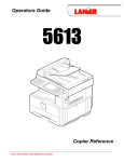
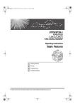
INSTRUCTION MANUAL
HF/50 MHz ALL BAND
1 kW LINEAR AMPLIFIER
iPW1
iPW1EURO
IMPORTANT
READ THIS INSTRUCTION MANUAL
CAREFULLY before attempting to operate the linear amplifier.
SAVE THIS INSTRUCTION MANUAL. This
instruction manual contains important safety and operating instructions for the IC-PW1/IC-PW1EURO.
PRECAUTION
RWARNING HIGH VOLTAGE! NEVER
attach an antenna or internal antenna connector during transmission. This may result in an electrical
shock or burn.
RWARNING! NEVER carry the linear amplifier
by yourself. At least two persons must carry the linear
amplifier since it weights approx. 25 kg (55 lb).
RWARNING! NEVER apply AC voltage until the
linear amplifier is grounded. Touching the linear amplifier may result in an electrical shock.
AVOID using or placing the linear amplifier or remote
controller in areas with temperatures below –10°C
(+14°F) or above +40°C (+104°F).
AVOID placing the linear amplifier or remote controller
in excessively dusty environments or in direct sunlight.
AVOID placing the linear amplifier against walls or
putting anything on top of the linear amplifier. This will
obstruct heat dissipation.
BE CAREFUL! The linear amplifier will become hot
when operating if continuously for long periods.
RNEVER apply AC voltage that exceeds the suggested voltage. This could cause a fire or ruin the
IC-PW1/EURO.
BE CAREFUL! Set the transceiver’s (exciter’s) RF
output power to less than 100 W, otherwise, the ICPW1/EURO will be damaged.
RNEVER use an extension cord with the AC power
cable. Extension cords may cause fire or electrical
shock.
RNEVER let metal, wire or other objects touch any
internal part or connectors on the panel of the linear
amplifier. This will cause electric shock.
During maritime mobile operation, keep the linear
amplifier, remote controller and microphone as far
away as possible from the magnetic navigation compass to prevent erroneous indications.
The IC-PW1/EURO cannot be used with the AH-2
AUTOMATIC ANTENNA TUNER.
HF
RNEVER expose the linear amplifier or remote controller to rain, snow or any liquids.
NEVER allow children to play with the linear amplifier or remote controller.
For U.S.A. only
CAUTION: Changes or modifications to this device,
not expressly approved by Icom Inc., could void your
authority to operate this device under FCC regulations.
DO NOT operate the IC-PW1/EURO before adjusting
the [ALC adj1] and [ALC adj2] pots properly on the
rear panel of the linear amplifier.
Icom, Icom Inc. and the
are registered trademarks of Icom Incorporated (Japan) in the United States, the
United Kingdom, Germany, France, Spain, Russia and/or other countries.
i
EXPLICIT DEFINITIONS
The explicit definitions described at left apply to this instruction manual.
WORD
DEFINITION
RWARNING
Personal injury, fire hazard or electric shock may occur.
CAUTION
Equipment damage may occur.
If disregarded, inconvenience only.
No risk of personal injury, fire or
electric shock.
NOTE
TABLE OF CONTENTS
IMPORTANT ...................................................... i
PRECAUTION ................................................... i
EXPLICIT DEFINITIONS ................................. ii
TABLE OF CONTENTS .................................. ii
SUPPLIED ACCESSORIES ............................ ii
1 PANEL DESCRIPTION ............................ 1–4
■ Front panel and remote controller ..................... 1
■ Rear panel ....................................................... 3
2 INSTALLATION AND CONNECTIONS 5–10
■ Unpacking ........................................................ 5
■ Ferrite core installation .................................... 5
■ OPC-853 AC cable with line filter .................... 5
■ Selecting a location ......................................... 5
■ AC power cable connection .............................. 5
■ Grounding ........................................................ 6
■ Antenna ........................................................... 6
■ System interconnections .................................. 7
■ Separating the remote controller ................... 11
3 OPERATION ......................................... 12–17
■ When first applying power (CPU resetting) ... 12
■ Setting the ALC levels ................................... 12
■ Programming the CI-V address ..................... 13
■ Initial settings for CI-V remote control operation
....................................................................... 14
■ Operation ....................................................... 16
■ Antenna tuner operation ................................ 17
■ Protection circuit ............................................ 17
4 MAINTENANCE ......................................... 18
■ Troubleshooting ............................................. 18
5 SPECIFICATIONS ..................................... 19
ABOUT CE ................................................ 20
SUPPLIED ACCESSORIES
q
w
e
r
t
y
i
o
u
Accessories included with the IC-PW1/EURO: Qty.
q Accessory cable (OPC-104B) .............................. 1
w Coaxial cable (OPC-125B) .................................. 1
e Separation cable (OPC-730) ............................... 1
r Remote control (CI-V) cable (OPC-718) .............. 1
t Remote controller feet ......................................... 2
y Grounding lug ...................................................... 1
u Dummy panel screws .......................................... 2
i Dummy panel ...................................................... 1
o Cable ties ............................................................. 2
ii
1
PANEL DESCRIPTION
■ Front panel and remote controller
!4
!5
!3
!2
!1
HF/50MHz ALL BAND 1kW LINEAR AMPLIFIER
POWER
q
w
100
250
10
20 30 40
Po
500
1K
1.5K
0
TRANSMIT
Po
0
ID
50
VD
0
ID
SWR
TEMP
ALC
W
60
1.5
1
SWR
A
HOT
VD
TEMP
2
40
50
1
2
60
3
∞
ALC ad j
INPUT
METER-2
1
TUNER
2
AMP/
PROTECT
DOWN AUTO
1.8
3.5
7
10
14
18
21
24
28
50
3
UP
4
t
ANT
y
u
i
o
HF/50MHz ALL BAND 1kW LINEAR AMPLIFIER
POWER
100
250
10
20 30 40
500
1K
0
TRANSMIT
Po
0
ID
50
Po
VD
ID
SWR
1.5K
0
W
60
HOT
VD
TEMP
1.5
2
40
50
1
2
60
3
∞
ALC ad j
ALC
TEMP
30
20
10
1
SWR
A
V
INPUT
ALC
METER-1
METER-2
1
TUNER
2
AMP/
PROTECT
DOWN
AUTO
1.8
3.5
7
10
14
18
21
24
28
50
UP
3
4
ANT
1
V
ALC
METER-1
e
r
30
20
10
!0
PANEL DESCRIPTION
q POWER SWITCH [POWER] (p. 12)
Push momentarily to turn power ON.
w TRANSMIT INDICATOR [TRANSMIT] (p. 16)
Lights green while transmitting.
During transmission, a humming may sound
depending on the output power. This is caused
by the large current produced by the power supply and does not indicate equipment malfunction.
e ANTENNA TUNER INDICATOR [TUNER] (p. 16)
• Lights while the antenna tuner is activated.
• Blinks while tuning and the SWR becomes 1.5:1
or greater on the 50 MHz band.
• Goes out after slow blinking when antenna turner
cannot tune the selected antenna (SWR 1.5:1 or
greater).
r ANTENNA TUNER SWITCH [TUNER] (p. 17)
• Turns the antenna tuner ON and OFF (bypass)
when pushed momentarily.
- The [TUNER] indicator lights while the antenna tuner is
activated; blinks while tuning.
- While operating in the 50 MHz band, the antenna
tuner does not start automatically. Push [TUNER] for
2 sec. to tune the antenna manually.
• Starts to tune the antenna manually when pushed
for 2 sec.
- When the tuner cannot tune the antenna (SWR 1.5:1
or greater), the tuning circuit is bypassed automatically after 20 sec.
t LINEAR AMPLIFIER SWITCH [AMP/PROTECT]
Turns the linear amplifier ON and OFF.
1
u AUTOMATIC INDICATOR [AUTO] (p. 16)
Indicates that automatic band selection is activated. (When an Icom CI-V transceiver is connected.)
i BAND INDICATORS (p. 16)
Indicate the selected operating band.
o UPPER BAND SELECTOR [UP] (p. 16)
Selects the higher operating band when pushed.
!0 OUTPUT ANTENNA SELECTOR [ANT] (p. 16)
Selects one of 4 output antenna connectors.
!1 INPUT ANTENNA SELECTOR [INPUT] (p. 16)
Selects one of 2 input antenna connectors.
!2 TRANSMIT METER-2 [METER-2]
Shows the final FET’s voltage (VD), SWR (Standing
Wave Ratio) or ALC (Automatic Level Control)
level.
!3 TRANSMIT METER-2 SELECTOR
Selects the final FET’s voltage (VD), SWR
(Standing Wave Ratio) or ALC (Automatic Level
Control) level for transmit meter-2.
!4 TRANSMIT METER-1 SELECTOR
Selects the RF output power (PO), final FET’s current (ID) or heatsink temperature (TEMP) for transmit meter-1.
!5 TRANSMIT METER-1 [METER-1]
Shows the RF output power (PO), final FET’s current (ID) or heatsink temperature (TEMP).
- The [AMP/PROTECT] indicator lights green when the
linear amplifier is ON. (p. 16)
- The [AMP/PROTECT] indicator lights red when the protector circuit is activated. (p. 17)
- When the linear amplifier is OFF, the [AMP/PROTECT]
does not light and the exciter’s signal is applied to one
of the output connectors or the IC-PW1/EURO’s antenna tuner.
y LOWER BAND SELECTOR [DOWN] (p. 16)
Selects the lower operating band when pushed.
2
1
PANEL DESCRIPTION
■ Rear panel
q
ANT4
w
ACC-2
ANT3
ANT2
ALC2 SEND2
ACC-1
INPUT1
ANT1
INPUT2
ALC1 SEND1
!1
EXCITER
1
CONTROLLER
e
r
t
y
u
REMOTE
ALC adj2
REMOTE
1&2
!0
ALC adj1
L
i
N
o
q OUTPUT ANTENNA CONNECTORS
[ANT1] – [ANT4] (p. 6)
Accept a 50 Ω antenna with a PL-259 connector.
w ACCESSORY SOCKET-1 [ACC-1]
ACCESSORY SOCKET-2 [ACC-2]
Enable connection to Icom exciters (transceivers).
- See the page at right for socket information.
- The [ACC-2] socket is connected in parallel with [ACC1] by default and can be used for connecting external
equipment such as the EX-627 AUTOMATIC ANTENNA
SELECTOR, etc. These sockets can be separated by the
[EXCITER] switch. (!0)
e REMOTE CONTROLLER CABLE HOLE [CONTROLLER] (p. 11)
Used for separation of the remote controller and linear amplifier.
r ALC OUTPUT JACKS [ALC1]/[ALC2] (p. 12)
Connect to the ALC input jack of a non-Icom exciter
(transceiver).
- Control voltage: –10 to 0 V DC
t SEND CONTROL JACKS [SEND1]/[SEND2]
(p. 9)
Input terminals for transmit control. Go to ground
while transmitting.
- Max. control level: 5.0 V DC/0.1 A
- Ground level: –0.5 to 0.8 V DC
y CI-V REMOTE CONTROL JACKS [REMOTE]
(pgs. 7–9)
Used for band control with an Icom CI-V exciter
(transceiver).
u ALC LEVEL ADJUSTMENT POTS
[ALC adj1]/[ALC adj2] (p. 12)
Adjust the ALC levels.
RCAUTION! DO NOT operate the ICPW1/EURO before adjusting the [ALC adj1] and
[ALC adj2] pots properly. This may damage the final
FETs.
i CIRCUIT BREAKERS (p. 17)
Cut off the AC input when over current occurs.
- Circuit breaker capacity: 20 A (U.S.A. version)
15 A (Europe version)
o GROUND TERMINAL (p. 6)
Connect this terminal to a ground to prevent electrical shocks, TVI, BCI and other problems.
3
PANEL DESCRIPTION
!0 EXCITER SELECTOR [EXCITER] (pgs. 7–9)
Sets the connected exciter number.
- Select [1] when 1 exciter is connected. [ACC-2] outputs
the received [ACC-1] signal to another Icom option
such as the EX-627 AUTOMATIC ANTENNA SELECTOR.
- Select [1&2] when 2 exciters or 1 exciter with 2 specified band antenna connectors is connected.
1
!1 INPUT ANTENNA CONNECTORS
[INPUT1]/[INPUT2] (p. 6)
Accept a 50 Ω antenna with a PL-259 connector.
D ACC-1 SOCKET
ACC-1
7
6
PIN NO. PIN NAME
Regulated reference 8 V DC input
for band control.
Input voltage
Input current
: 8 V ±0.3 V
: Less than 10 mA
8V
2
GND
3
SEND
Input/output pin.
Goes to ground when transmitting.
When grounded, transmits.
Ground level
Output current
Input current
: –0.5 V to 0.8 V
: Less than 20 mA
: Less than 200 mA
4
BAND
Band voltage input.
(Varies with amateur band)
Input voltage
: 0 to 8.0 V
5
ALC
ALC voltage output.
Control voltage
: –10 to 0 V
Output impedance : 10 kΩ
6
NC
7
13.8 V
5 2 4
Rear panel
view
SPECIFICATIONS
1
1
3
DESCRIPTION
Connects to ground.
No connection.
13.8 V DC input terminal.
Input current
: Less than 1 A
D ACC-2 SOCKET (w/[EXCITER] is “1”)
The following descriptions are applied when the
[EXCITER] switch is set to “1” (default). When
[EXCITER] is set to “1&2,” [ACC-2] functions the
same as [ACC-1] above for the 2nd exciter.
ACC-2
7
PIN NO. PIN NAME
Rear panel
view
Regulated reference 8 V DC output
from the [ACC-1] socket.
Output voltage
Output current
: 8 V ±0.3 V
: Less than 10 mA
8V
2
GND
3
SEND
Input/output pin.
Goes to ground when transmitting.
When grounded, transmits.
Ground level
Output current
Input current
: –0.5 V to 0.8 V
: Less than 20 mA
: Less than 200 mA
4
BAND
Band voltage output from the
[ACC-1] socket.
(Varies with amateur band)
Output voltage
: 0 to 8.0 V
5
ALC
ALC voltage output.
Control voltage
: –10 to 0 V
Output impedance : 10 kΩ
6
NC
7
13.8 V
1
5 2 4
SPECIFICATIONS
1
6
3
DESCRIPTION
Connects to ground.
No connection.
13.8 V DC output terminal from the
[ACC-1] socket.
Output current
: Less than 1 A
4
2
INSTALLATION AND CONNECTIONS
■ Unpacking
■ AC power cable connection
After unpacking, immediately report any damage to the
delivering carrier or dealer. Keep the shipping cartons.
A suitable AC power plug must be connected to the
AC power cable end. See the diagram below for connection procedures. AC input voltage is automatically
selected.
For a description and a diagram of accessory equipment included with the IC-PW1/EURO, see SUPPLIED ACCESSORIES on p. ii of this manual.
■ Ferrite core installation
The supplied cable ties (o in SUPPLIED ACCESSORIES) should be attached to the AC cable of the
IC-PW1/EURO as illustrated below.
Attach and position
the cable ties to
the AC cable
as illustrated.
The IC-PW1/EURO can accept either 100–120 V AC
or 200–240 V AC power.* However, we recommend
using 200–240 V AC rather than 100–120 V AC for
better power supply efficiency and longer periods of
transmission.
* Europe version: 230 V AC only
D Single-phase 3-wire line (200–240 V AC)
q The green wire from the AC power cable must be
connected to the protective earth.
w The black and white wires from the AC power cable
can be connected to either terminal.
*Use the appropriate AC plug if required.
Ferrite core
AC cable
Cut the cable ties
so that enough
length remains to
secure the ferrite
core in place.
*
white
black
green
NOTE: Only one ferrite core is attached with the ICPW1EURO.
■ OPC-853 AC cable with line filter
The IC-PW1EURO must be used with the OPC-853
AC cable to satisfy European R&TTE requirements.
D Single-phase 2-wire line (100–120 V AC)
q The green wire from the AC power cable must be
connected to the protective earth.
w The black wire from the AC power cable must be
connected to the hot (live) wire.
e The white wire from the AC power cable must be
connected to the return wire.
■ Selecting a location
Select a location for the linear amplifier that allows
adequate air circulation, free from extreme heat, cold,
or vibrations, and away from TV sets, TV antenna elements, radios and other electro-magnetic sources.
The linear amplifier and remote controller sections of
the IC-PW1/EURO can be separated. The remote
controller can be placed near the operator for easy
monitoring of linear amplifier conditions at any time.
See p. 10 for separation instructions.
The linear amplifier must be placed on a solid foundation since it is very heavy.
white
black
green
GND
D Three-phase 3-wire line (200–240 V AC)
q The green wire from the AC power cable must be
connected to the protective earth.
w The black and white wires from the AC power cable
can be connected to 2 of 3 wires.
white
black
green
5
INSTALLATION AND CONNECTIONS
2
■ Grounding
To prevent electrical shock, television interference
(TVI), broadcast interference (BCI) and other problems, ground the linear amplifier through the
GROUND terminal on the rear panel.
For best results, connect a heavy gauge wire or strap
to a long earth-sunk copper rod. Make the distance
between the GROUND terminal and ground as short
as possible.
R WARNING: NEVER
connect the
GROUND terminal to a gas or electric pipe, since
the connection could cause an explosion or electric
shock.
■ Antenna
For radio communications, the antenna is of critical
importance, along with output power and sensitivity.
Select antenna(s), such as a well-matched 50 Ω
antenna with more than 2 kW power rating, and feedline. 1.5:1 of Voltage Standing Wave Ratio (VSWR) is
recommended for a desired band. Of course, the
transmission line should be a coaxial cable.
When using 1 antenna, use the [ANT1] connector.
CAUTION: Protect your linear amplifier from
Antenna SWR
Each antenna is tuned for a specified frequency
range and SWR may be increased out-of-range.
When the SWR is higher than approx. 2.0:1, the linear amplifier’s power drops to protect the final FET.
In this case, an antenna tuner is useful to match the
linear amplifier and antenna. Low SWR allows full
power for transmitting even when using the antenna
tuner. The IC-PW1/EURO has an SWR meter to
monitor the antenna SWR continuously.
lightning by using a lightning arrestor.
PL-259 CONNECTOR INSTALLATION
30 mm
Coupling ring
10 mm (soft solder)
10 mm
Soft
solder
1–2 mm
q Slide the coupling ring down. Strip the cable jacket and soft solder.
w Strip the cable as shown at left. Soft solder the
center conductor.
Solder Solder
e Slide the connector body on and solder it.
r Screw the coupling ring onto the connector body.
30 mm ≈ 9⁄8 in 10 mm ≈ 3⁄8 in 1–2 mm ≈ 1⁄16 in
6
2
INSTALLATION AND CONNECTIONS
■ System interconnections
1 or 2 Icom 100 W HF transceivers can be connected
as exciters to the IC-PW1/EURO. Non-Icom transceivers can be used, however, band selection will not
be synchronized for each exciter.
See the following diagrams for making connections
between the IC-PW1/EURO and an exciter (transceiver). See p. 5 for AC power cable connection.
CAUTION!: When connecting the supplied ACC
cable to an Icom transceiver, be sure to connect the
cable to the 7-pin [ACC(2)] jack on the exciter
(transceiver) side.
Icom standard 8 and 7-pin accessory jacks
(transceiver side)
If the ACC cable is connected to the 8-pin [ACC(1)]
jack, the protector circuit in the IC-PW1/EURO will
not able to read the ALC signal. If operation continues using this setup, damage (including the possibility of explosion) to the connected transceiver and/or
IC-PW1/EURO will occur.
[ACC(1)]
[ACC(2)]
2
4
5
1
8 3
6
7
4
1
6
2
5
3
7
• Using 1 Icom exciter (transceiver)
To an
antenna
ANT
Remote control cable (supplied)
ACC cable (supplied)
ACC-1
Be sure to connect the cable
to the 7-pin ACC(2) jack.
REMOTE
INPUT1
Coaxial cable (supplied)
INPUT2
Coaxial cable
(optional)
ANT2
EXCITER
1
1&2
Connect
[INPUT2]
if necessary.
ANT1 ACC(2)
GND
GND
IC-PW1/EURO
AC outlet
(IC-PW1
: 100–120/220–240 V
IC-PW1EURO : 230 V)
7
Ground
IC-756
REMOTE
INSTALLATION AND CONNECTIONS
2
• Using a 13-pin ACC socket (IC-706 series)
Remote control cable (supplied)
To an
antenna
OPC-599 (optional)
ACC-1
ACC cable (supplied)
REMOTE
ANT
ACC (13 pins)
INPUT1
REMOTE
ANT1
Coaxial cable
(supplied)
GND
IC-706 series
EXCITER
1
1&2
GND
IC-PW1/EURO
Ground
AC outlet
(IC-PW1
: 100–120/220–240 V
IC-PW1EURO : 230 V)
The following connections also apply to transceivers having multiple antenna connectors for
specified bands (e.g. IC-726, IC-729, etc.)
• Using 2 Icom exciters (transceivers)
Remote control cable (supplied)
To an
antenna ACC-1
OPC-599 (optional)
ACC cable (supplied)
ACC
ANT
REMOTE
Coaxial cable (supplied)
REMOTE
ANT1
INPUT1
ACC-2
INPUT2
GND
OPK-5
(optional)
REMOTE
ANT1 or 2
EXCITER
1
1&2
IC-706 series
IC-756
GND
GND
Ground
IC-PW1/EURO
AC outlet
ACC(2)
(IC-PW1
: 100–120/220–240 V
IC-PW1EURO : 230 V)
Optional ACC cable (includedn in the OPK-5)
REMOTE
Optional remote control cable (includedn in the OPK-5)
Be sure to connect the cable to the 7-pin ACC(2) jack.
8
2
INSTALLATION AND CONNECTIONS
• Using a non-Icom exciter (transceiver)
NOTE: The specifications for the SEND relay are
5 V DC 0.1 A. If this level is exceeded, a large
external relay must be used.
Set the [EXCITER] switch to [1] when 1 exciter is connected; set to [1&2] when 2 exciters are connected.
To an antenna
ALC1
RCA plug
ALC
SEND1
ANT
SEND
INPUT1
SEND
DC power
Relay
EXCITER
1
1&2
GND Coaxial cable
(supplied)
RF OUT
DC OUT SEND ALC
GND
IC-PW1/EURO
AC outlet
(IC-PW1
: 100–120/220–240 V
IC-PW1EURO : 230 V)
Ground
NOTE: The specifications for the SEND relay are
5 V DC 0.1 A. If this level is exceeded, a large
external relay must be used.
• Using 1 Icom and 1 non-Icom exciters
(transceivers)
To an
antenna
ACC-1
Non-Icom exciter
ACC cable (supplied)
Be sure to connect the cable to the 7-pin ACC(2) jack.
Remote control cable (supplied)
ACC(2)
ANT
REMOTE
REMOTE
Coaxial cable (supplied)
Connect
ANT1 or
ANT2
INPUT1
INPUT2
GND
IC-756
EXCITER
1
1&2
GND
IC-PW1/EURO
AC outlet
(IC-PW1
: 100–120/220–240 V
IC-PW1EURO : 230 V)
SEND2
Ground
Coaxial cable
(optional)
SEND
SEND
Relay
ALC2
DC power
RCA plug
ALC
9
Non-Icom exciter
ANT
RF OUT
SEND DC OUT ALC
GND
INSTALLATION AND CONNECTIONS
2
• Using non-Icom exciters (transceivers) when the IC-PW1/EURO’s power is OFF
To use the antenna selector of the IC-PW1/EURO
while the power is OFF, follow 1 of 2 methods.
(1) Supply the antenna selector power to the
ACC-1 socket
Supply the 13.8 V DC, 0.5 A to pin 7 of the [ACC-1]/
[ACC-2] socket.
- Use [ACC-1] when the exciter is connected to [INPUT1].
- Use [ACC-2] when the exciter is connected to [INPUT2].
to IC-PW1/EURO [INPUT1]
[ACC-1]
13.8 V DC
to IC-PW1/EURO [GND]
6
1
3
GND
RF
5 2 4
(2) Use the auxiliary power supply
Set the jumper to ‘2’ to use the auxiliary power supply as shown at right.
- The antenna selector functions even when the ICPW1/EURO power is OFF
In addition set the jumper on the IC-PW1/EURO controller to ‘2’ to turn the controller’s LEDs OFF as
shown at right.
When the jumper is set to ‘2,’ the CI-V control does
not function even if an Icom exciter is connected.
•Jumper location of linear amplifier
DC SEND ALC
IC-PW1/EURO (DIN)
Non-Icom exciter
J3
S3
J4
2
1
• Jumper location of controller
1 2
These diagrams show the factory defaults.
NOTE: When using the antenna selector of the IC-PW1/EURO while the power is OFF, as above, tuner intialization of the IC-PW1/EURO may not be performed correctly if the applied voltage is insufficient.
Check that the applied voltage to pin 7 of [ACC-1]/[ACC-2] socket is 13.8 V DC.
10
2
INSTALLATION AND CONNECTIONS
■ Separating the remote controller
The control section of the linear amplifier can be separated from the main body, doubling as a remote controller. It can be placed on the exciter or in another
convenient place.
y Replace the control cable with the supplied separation cable through the cable hole. Use the shorter end (from the bushing) to connect to the remote
controller.
Control cable
q Disconnect the AC power cable.
w Remove 8 screws from the sides of the linear
amplifier, then lift up the top cover.
JACK unit
Separation cable
MAIN unit
u Remove 2 screws from the cable hole cover on
the linear amplifier rear panel. Insert the separation cable into the cable hole. Keep the hole cover
and screws for future use.
(Fig. 1)
Longer end
(from the bushing)
Control cable
(step i)
OLLER
CONTR
J3
Control cable (step e)
(Fig. 2)
e Unplug the control cable from J3 on the MAIN unit.
r Remove 2 screws from the front panel of the linear amplifier, then detach the remote controller.
(Fig. 1) Attach the dummy panel onto the space
left by the controller using the 2 screws.
i Plug the other longer end (from the bushing) of the
separation cable into J10 on the JACK unit
through the cable hole. Connect the grounding
wire as shown below. Connect the control cable to
J11.
Control cable
J11
To J3
(MAIN)
t Remove 5 screws from the rear panel of the
remote controller, then remove the rear panel.
Separation cable
J10
JACK unit
o Plug the other end of the control cable into J3 on
the MAIN unit. (Fig. 2)
!0 Replace the top cover and 8 screws.
11
OPERATION
3
■ When first applying power (CPU resetting)
Before first applying power, make sure all connections required for your system are complete by referring to chapter 2. Then, reset the linear amplifier
using the following procedure.
NOTE: Resetting CLEARS all programmed settings to default values.
If the controller’s power is supplied from non-Icom
exciters or auxiliary power supply (p. 10), turn the
exciter or auxiliary power supply ON while pushing
[UP] and [DOWN] to reset the CPU.
[POWER]
q Make sure the linear amplifier, exciter and auxiliary power supply (p. 10) powers are OFF.
w While pushing [UP] and [DOWN], push [POWER]
to turn power ON.
- The internal CPU is reset.
- The remote controller shows its initial condition when
resetting is complete.
e Reset the exciter’s CI-V settings after resetting.
(pgs. 13, 14)
[DOWN]
[UP]
■ Setting the ALC levels
R CAUTION: Final FETs may be damaged if
the ALC level adjustment is set incorrectly.
y Push the transmit meter-2 switch one or more
times to select the ALC level meter.
- The [ALC] indicator lights.
NOTE: Re-adjustment is necessary when replacing the exciter.
q Select an antenna which has an SWR of 1.5:1 or
better.
w Set the 1st exciter’s RF output power for the minimum output.
e Be sure that the [ALC adj1] and [ALC adj2] pots on
the rear panel max. counterclockwise. (default)
[ALC adj2] [ALC adj1]
u Push [TUNER] to turn the antenna tuner ON.
- The [TUNER] light lights.
i While adjusting the 1st exciter’s RF output power,
transmit a 100 W output power of the selected
band signal using CW or RTTY mode.
o Adjust the [ALC adj1] pot to the ALC adjustment
point as shown below.
VD
1
30
20
10
0
2
1.5
SWR
40
50
ALC adjustment
point
60
3
V
∞
ALC adj
ALC
METER-2
!0 Check that the Po meter shows 1 kW output
power.
100
250
10
20 30 40
500
1K
0
Po
0
ID
50
HOT
Output power
1.5K
W
60
A
TEMP
METER-1
r Push [POWER] to turn the linear amplifier power
ON.
t Push [UP] or [DOWN] to select an operating band
except 50 MHz band.
!1 Adjust the [ALC adj2] pot in the same manner
when a 2nd exciter is connected.
- Select a band which uses a well-matched 50 Ω antenna.
12
3
OPERATION
■ Programming the CI-V address
The IC-PW1/EURO uses CI-V frequency data for
automatic selection of the operating band. Program
the exciter’s address to use this capability as follows:
For non-Icom exciters, the IC-PW1/EURO cannot
be controlled using the CI-V function, so this setting is not necessary.
D When using 1 Icom exciter
q While pushing [INPUT], push [POWER] to enter
the CI-V address programming mode.
- [INPUT z] blinks.
HF/50MHz ALL BAND 1kW LINEAR AMPLIFIER
z
TRANSMIT
For transceivers which have multiple antenna connectors for specified bands (e.g. IC-726, IC-729,
etc.), set the same as for 2 Icom exciters.
iPW1
POWER
Po
VD
ID
SWR
TEMP
ALC
x
INPUT
METER-1
METER-2
z
TUNER
AMP/
PROTECT
x
DOWN
AUTO
1.8
3.5
7
10
14
18
21
24
28
50
UP
c
v
ANT
D Setting the Icom exciters
When connecting 2 or more CI-V devices:
DO NOT use the “AUTO” baud rate for CI-V
devices. We recommend that all CI-V devices are
set to 9600 bps.
• When using the same baud rate, the exciters’ frequencies are synchronized.
• When using different baud rates (i.e. 4800 and
9600 bps, etc.), the exciters’ frequencies are not
synchronized.
q Confirm that the exciter’s CI-V transceive function
is ON.
w When connecting 2 exciters, connect the 1st and
2nd exciter to [INPUT1] and [INPUT2], respectively.
e When connecting 2 Icom exciters, set [EXCITER]
to the [1&2] position.
r When connecting 2 or more CI-V devices, DO
NOT set to “AUTO” baud rate.
- Refer to the instruction manual for details.
- When using the same baud rate, the exciters’ frequencies are synchronized.
- When using different baud rates (i.e. 4800 and 9600
bps, etc.), the exciters’ frequencies are not synchronized. [INPUT z] and [INPUT x] selection is automatically selected using the exciter’s baud rate.
• DO NOT USE CT-17 CI-V LEVEL CONVERTER to connect the remote control signal line for band control
operation from an Icom exciter, or from the PC.
• Connect the supplied remote cable between the ICPW1/EURO and Icom exciter directly.
Icom transceiver
(e.g. IC-756 etc.)
to REMOTE
PC
CT-17
to REMOTE
13
D When using 2 Icom exciter’s
q When using 2 Icom exciters, be sure that
[EXCITER] is set to the [1&2] position.
w While pushing [INPUT], push [POWER] to enter
the CI-V address programming mode.
- [INPUT z] blinks.
HF/50MHz ALL BAND 1kW LINEAR AMPLIFIER
iPW1
z
POWER
- Refer to the instruction manual for details.
IC-PW1/EURO
w Rotate the Icom exciter’s tuning dial until the
[INPUT z] light continuously lights.
e Push [POWER] to turn the IC-PW1/EURO power
OFF and complete the setting.
TRANSMIT
Po
VD
ID
SWR
TEMP
ALC
x
INPUT
METER-1
METER-2
z
TUNER
AMP/
PROTECT
x
DOWN
AUTO
1.8
3.5
7
10
14
18
21
24
28
50
UP
c
v
ANT
e Push [DOWN].
- The band indicators, [1.8]–[50], light continuously.
r Rotate the 1st Icom exciter’s tuning dial until the
[INPUT z] light continuously lights.
t When 1 Icom exciter and 1 non-Icom exciter are
connected, turn the power OFF to complete the
setting. When 2 Icom exciters are connected,
push [INPUT].
- [INPUT x] blinks when [INPUT] is pushed.
y Rotate the 2nd Icom exciter’s tuning dial until the
[INPUT x] light continuously lights.
u Push [POWER] to complete the setting.
☞Continue to the next page…
OPERATION
3
■ Programming the CI-V address (continued)
D Setting the IC-PW1/EURO’s address
ï Other NOTE:
It is not necessary to change the IC-PW1/EURO’s
default CI-V address of 54H. However, if desired, the
address can be changed using the internal address
switch illustrated below.
• IC-781;
NEVER TURN THE POWER OFF of the IC-781 during the operation when you are using the IC-781 as
one of the exciters, otherwise the CI-V control may
be interrupted.
Icom
exciter
IC-PW1
• Baud rate;
Higher baud rate (e.g. 9600 bps) gives quick operation. When you select an extra Low baud rate (e.g.
300 bps), then the IC-PW1/EURO needs max. 15
sec. to start the operation.
REMOTE
Icom
exciter
IC-PW1
Address switch
It is not necessary to change the IC-PW1/EURO’s
default CI-V address (default S3=5, S4=4). However,
in the case when you will connect two (2) ICPW1/EUROs like as above left1, please set a different address number using the internal address switch
as illustrated as above right.
• “AUTO” baud rate;
When you want to use “AUTO” baud rate, turn the
non-“AUTO” baud rate exciter ON first, then turn the
“AUTO” baud rate exciter ON.
➥ Push [POWER] to turn the linear amplifier ON
then turn the exciter’s power ON.
NOTE: Turn the power OFF when you are going to
change the address setting, then programming the
CI-V address again.
‘ Initial settings for CI-V remote control operation
Before setting the remote control operation, refer to
the following operating procedure.
ï When using one (1) Icom exciter with one (1)
ANT line;
ANT
ï When using two (2) Icom exciters;
ACC -1
ACC (supplied)
OPC -599 (optional)
OPC-599 (optional)
ACC -1
ACC (13 pins)
ANT
REMOTE
ACC cable (supplied)
REMOTE
ACC
REMOTE
ACC -2
INPUT2
INPUT1
ANT1 or 2
GND
GND
REMOTE
ANT1
EXCITER
1
1&2
GND
EXCITER
1
1&2
REMOTE
ANT1
INPUT1
GND
IC-706
GND
IC - PW1/EURO
GND
Optional ACC cable (included in OPK-5)
ACC(2)
Optional remote control cable (included in OPK-5)
REMOTE
IC - PW1/EURO
q Turn OFF both of the IC-PW1/EURO and exciter.
w Set [EXCITER] to [1] position.
e While pushing and holding the [INPUT] switch on
the IC-PW1/EURO controller, turn the exciter’s
power ON.
• LED [INPUT z] over the [INPUT] switch blinks.
r Rotate the exciter’s dial until the LED [INPUT z]
lights continuously.
t Turn the exciter’s power OFF to complete the setting.
q Turn OFF both of the IC-PW1/EURO and exciters.
w Set [EXCITER] to [1&2] position.
e Set the exciter’s CI-V baud rate if required.
• When selecting the different baud rate for each exciter,
“CI-V data” setting may fail depending on the exciter.
In such case, use the same baud rate for each exciter.
Each exciter’s frequencies may be synchronised.
• When connecting the “AUTO” baud rate exciter and
“Non-AUTO” baud rate exciter, the exciters’ frequencies may not synchronize in some cases.
r While pushing and holding the [INPUT] switch on
the IC-PW1/EURO controller, turn the 1st exciter’s
power ON.
• LED [INPUT z] blinks.
☞Continue to the next page
14
3
OPERATION
‘ Initial settings for CI-V remote control operation (continued)
t Push [DOWN] to turn the position memory function
for the [INPUT] select switch ON.
ï When using one (1) Icom and one (1) nonIcom exciter;
• The band indicators, [1.8]–[50], light continuously.
y Rotate the 1st exciter’s dial until the LED [INPUT
z] lights continuously.
u Turn the 2nd exciter’s power ON.
i Push [INPUT].
ACC cable
REMOTE
ANT
ACC(2)
INPUT1
INPUT2
REMOTE
ANT1 or 2
GND
• LED [INPUT x] blinks.
o Rotate the 2nd exciter’s dial until the LED [INPUT
x] lights continuously.
!0 Turn both exciter’s power OFF to complete the
setting.
EXCITER
1
1&2
GND
ANT
RF OUT
IC - PW1/EURO
SEND
ALC
GND
GND
SEND
SEND 2
ï When using one (1) Icom exciter with two (2)
ANT lines (e.g. IC-756PRO etc.);
SEND
DC power
D
Relay
ACC -1
ANT
REMOTE
INPUT1
INPUT2
ACC (2)
ANT2
EXCITER
1
1&2
RCA plug
RC
ALC 2
ACC cable
REMOTE
ANT1
GND
q Turn OFF both the IC-PW1/EURO and exciters.
w Set [EXCITER] to [1&2] position.
e While pushing and holding the [INPUT] switch on
the IC-PW1/EURO controller, turn the 1st exciter’s
power ON.
• LED [INPUT z] over the [INPUT] switch blinks.
GND
IC - PW1/EURO
IC-756
q Turn OFF both the IC-PW1/EURO and exciter.
w Set [EXCITER] to [1] position.
e While pushing and holding the [INPUT] switch on
the IC-PW1/EURO controller, turn the exciter’s
power ON.
• LED [INPUT z] blinks.
r Rotate the exciter’s dial until the LED [INPUT z]
lights continuously.
t Turn the exciter’s power OFF to complete the setting.
ï When using two (2) non-Icom exciters;
ALC
SEND
SEND 1
SEND
ANT
INPUT 1
r Rotate the exciter’s dial until the LED [INPUT z]
lights continuously.
t Push [INPUT].
INPUT 2
• LED [INPUT x] blinks.
DC power
Relay
Non-Icom exciter
ANT
ALC
EXCITER
1
1&2
RF OUT
DC
power SEND ALC
y Rotate the exciter’s dial until the LED [INPUT x]
lights continuously.
GND
Non-Icom exciter
IC-PW1/EURO
RF OUT
DC
SEND power ALC
GND
GND
RCA plug
SEND
SEND 2
SEND
DC power
Relay
ALC 2
➥ Set [EXCITER] to [1&2] position, only.
*No other setting is required.
15
GND
GND
• The band indicators, [1.8]–[50], turn OFF.
• “AUTO” indicator lights continuously.
u Turn the exciter’s power OFF to complete the setting.
RCA plug
ALC 1
OPERATION
3
■ Operation
CAUTION:
DO NOT operate the IC-PW1/EURO before
adjusting the ALC levels properly with the [ALC
adj1] and [ALC adj2] pots. (p. 11)
It takes 15 sec. for CI-V line initial settings when
several CI-V devices (more than 5) are connected
to a CI-V line.
For IC-781 users with other Icom CI-V transceivers:
Turn the IC-781 power ON before turning the ICPW1/EURO and other transceiver power ON and
keep the IC-781 power ON during operation.
q Push [POWER] to turn the linear amplifier ON
then turn the exciter’s power ON.
[POWER]
HF/50MHz ALL BAND 1kW LINEAR AMPLIFIER
iPW1
z
POWER
Po
VD
ID
SWR
TEMP
ALC
TRANSMIT
x
INPUT
METER-1
METER-2
z
TUNER
AMP/
PROTECT
x
DOWN
AUTO
1.8
3.5
7
10
14
18
21
24
28
50
UP
c
v
ANT
w Select the input/output antenna with [INPUT] and
[ANT].
e Set the exciter to CW or RTTY mode with minimum output power.
r Select the temperature and SWR meters with
[METER-1] and [METER-2].
- The [TEMP] and [SWR] indicators light.
HF/50MHz ALL BAND 1kW LINEAR AMPLIFIER
iPW1
z
POWER
TRANSMIT
Po
VD
ID
SWR
TEMP
ALC
x
INPUT
METER-1
METER-2
z
TUNER
AMP/
PROTECT
y Push [UP]/[DOWN] to select [AUTO] for automatic band selection when a CI-V Icom exciter is
used; or push [UP]/[DOWN] to select the desired
band for manual band selection.
u Use the exciter’s antenna tuner to tune the line
between the IC-PW1/EURO and exciter, if you
have an antenna tuner connected to the exciter.
i Transmit with the exciter and adjust the exciter’s
output power to 50 W with the RF output power
control on the exciter.
- [TRANSMIT] indicator lights.
- See the exciter’s instruction manual for transmitting.
o The built-in antenna tuner automatically tunes the
antenna.
- SWR reading on meter-2 should be less than 1.2:1.
- Push [TUNER] for 2 sec. to tune the antenna manually.
- The [TUNER] indicator blinks while tuning.
- The [TUNER] indicator lights while the tuner is activated.
NOTE: The band information is not updated while
scanning. Turn the antenna tuner OFF and use the
manual band selection while scanning.
During split operation:
When changing the frequency more than 100 kHz,
the IC-PW1/EURO’s antenna tuner presets the
tuner to the new frequency. Use manual tuning
during split operation.
!0 When operating for long periods, select the temperature meter with [METER-1] to monitor the linear amplifier’s temperature.
- If the temperature meter reading is in the red “HOT”
zone, the exciter should be returned to receive, otherwise, the protection circuit may be activated and the
linear amplifier may be turned OFF.
x
DOWN
AUTO
1.8
3.5
7
10
14
18
21
24
28
50
UP
c
v
ANT
Temperature
protection range
t Push [TUNER] and [AMP/PROTECT] to turn the
automatic antenna tuner and linear amplifier circuit ON.
HF/50MHz ALL BAND 1kW LINEAR AMPLIFIER
iPW1
z
POWER
TRANSMIT
Po
VD
ID
SWR
TEMP
ALC
x
INPUT
METER-1
METER-2
z
TUNER
AMP/
PROTECT
x
DOWN
AUTO
1.8
3.5
7
10
14
18
21
24
28
50
UP
c
v
ANT
[AMP/PROTECT]
[TUNER]
METER-1
D Band memory
The IC-PW1/EURO stores ON/OFF settings for the
antenna tuner and linear amplifier according to the
operating band when at least 1 Icom exciter is connected to the [INPUT1] connector.
The set conditions may not be stored when the linear amplifier is turned OFF immediately after setting the antenna tuner and linear amplifier.
16
3
OPERATION
■ Antenna tuner operation
The built-in automatic antenna tuner can match the
antenna feed line impedance to 50 Ω when the feed
line impedance is within 16.7 to 150 Ω for HF bands
(VSWR 3:1) or within 20 to 125 Ω for 50 MHz bands
(VSWR 2.5:1).
Once the tuner matches an antenna, the tuning circuit condition is memorized as a preset point for each
frequency range (100 kHz steps, 70 ranges).
Therefore, when you change the frequency range,
the tuning circuit is automatically preset to the memorized point.
This antenna tuner is also used when the linear
amplifier is turned OFF.
➥ Push [TUNER] for 2 sec. to start manual antenna
tuning.
• When the tuner cannot tune the antenna (SWR 1.5:1 or
greater), the tuning circuit is bypassed automatically
after 20 sec.
While operating in the 50 MHz band, the antenna
tuner does not start automatically. Push [TUNER]
for 2 sec. to tune the antenna manually.
■ Protection circuit
This linear amplifier has various protection circuits.
D ALC circuit
The ALC (Automatic Level Control) circuit automatically limits RF output power by controlling the input
level of the exciter. This prevents transmission of distorted signals when the input signal level exceeds the
allowable level.
D Linear amplifier protection circuit
When a protection circuit is activated, a band indicator blinks to show a problem as described below.
➥ [AMP/PROTECT] lights red when a protection circuit is activated.
- Push [AMP/PROTECT] to cancel the protection circuit.
Item
Indication
Possible cause
The ALC activates under the following conditions:
1
[TEMP]
- Output power of the linear amplifier exceeds 1 kW
- Antenna SWR becomes 2:1 or more
- Output power of the exciter exceeds 100 W
The heatsink temperature of the
final FETs exceeds 100°C
(212°F).
2
[AUTO]
Power level of the 4 PA units
becomes unbalanced.
3
[ALC]
ALC control level exceeds the
control range.
4
[VD]
Output voltage of the internal
power supply exceeds 55 V DC.
5
[ID]
Current of the final FETs (ID)
exceeds 50 A.
6
Current band’s
indicator
Gain of the final FETs drops.
7
Selected and
current band’s
indicator
When transmitting with different
band selections between the linear amplifier and exciter.
8
[AMP/PROTECT]
The power supply has a malfunction.
D Cooling fans
• The power supply cooling fans activate when the linear amplifier is activated and while transmitting.
• The antenna tuner cooling fans activate when the
antenna tuner is activated and while transmitting.
• All cooling fans activate when the heatsink temperature of the final FETs reaches 50 °C (122 °F) or
more.
D Circuit breaker
If the circuit breaker activates or the linear amplifier
stops functioning, try to find the source of the problem, then push the circuit breaker button to fill the
white parts.
- Circuit breaker capacity: 20 A (U.S.A. version)
15 A (Europe version)
17
MAINTENANCE
4
■ Troubleshooting
The following chart is designed to help you correct
problems which are not equipment malfunctions.
PROBLEM
If you are unable to locate the cause of a problem or
solve it through the use of this chart, contact your
nearest Icom Dealer or Service Center.
POSSIBLE CAUSE
Power does not come • Cable connection is faulty.
on when the [POWER]
switch is pushed.
• The circuit breaker is turned OFF.
Sensitivity is low.
SOLUTION
REF.
• Check the connection and connection cable pgs.
7–10
pins.
• Check for the cause, then turn the circuit p. 3
breaker ON.
p. 6
• The antenna is not connected properly. • Reconnect the antenna connector.
• The antenna for another band is select- • Select an antenna suitable for the operating p. 16
frequency.
ed.
• Push [TUNER] for 2 sec. to manually tune the p. 17
• The antenna is not properly tuned.
antenna.
• Check the connection and connection cable pgs.
Operating band does • Cable connection is faulty.
7–10
pins.
not change automatip. 13
cally.
• CI-V setting is not properly pro- • Set the CI-V address.
grammed.
pgs.
7–10
p. 12
• Set [ALC adj] properly.
• Push [AMP/PROTECT] to turn the linear p. 16
amplifier ON. (The indicator lights green.)
• Select an antenna suitable for the operating p. 16
frequency.
• Push [TUNER] for 2 sec. to manually tune the p. 16
antenna.
• The protection circuit activates and a • Stop the exciter’s transmission, then push p. 17
[AMP/PROTECT] to deactivate the protection
band indicator blinks.
circuit.
Output power is too • Reverse connection on the antenna
input and output.
low.
• [ALC adj] is not adjusted properly.
• The linear amplifier circuit is turned
OFF.
• The antenna for anther band is selected.
• The antenna is not properly tuned.
• Connect properly.
Protection circuit acti- • Antenna SWR is more than 3:1.
vates during short peri• The antenna tuner is turned OFF.
ods of operation.
• The linear amplifier is located in an area
with bad air circulation.
• [ALC adj] is not adjusted properly.
• Check the antenna SWR. Adjust the antenna, p. 6
if necessary.
• Push [TUNER] to turn the antenna tuner ON. p. 17
• Select a location with good air circulation.
—
• Adjust [ALC adj] to the correct position.
p. 12
18
5
SPECIFICATIONS
■ General
■ Transmitter
• Frequency coverage: 01.800–01.999 MHz
03.500–13.999 MHz
07.000–17.300 MHz
10.100–10.150 MHz
14.000–14.350 MHz
18.068–18.168 MHz
21.000–21.450 MHz
24.890–24.990 MHz*1
28.000–29.700 MHz*1
50.000–54.000 MHz
• Output power
*1 The U.S.A. version can only be
used the antenna tuner on the
24–28 MHz bands.
• Antenna connector
Input
Output
:
PL-239 × 2 (50 Ω)
PL-239 × 4 (50 Ω)
• Usable temperature : –10°C to 40°C (14°F to 104°F)
range
• Power supply requirement:
non-Europe versions 100–120 V AC or
200–240 V AC (±10 %)
Europe version
230 V AC (±10 %)
• Dimensions (W × H × D):
Linear amplifier
350 × 265 × 375 mm
13 25⁄32 × 10 7⁄16 × 14 3⁄4 in
Remote controller 205 × 71 × 68.3 mm
8 1⁄16 × 2 25⁄32 × 2 11⁄16 in
INPUT AC VOLTAGE
MODE
200–240 V AC
100–120 V AC
CW, RTTY
1 kW
500 W
SSB
1 kW PEP
500 W PEP
• Driving power
: Approx. 25 kg (55 lb)
(incl. remote controller)
• CI-V connector
: 2-conductor 3.5(d) mm (1⁄8")
: 100 W max.
• Spurious emissions : –60 dB (HF bands)
–70 dB (50 MHz band)
• SEND connector
: Phono (RCA)
• ALC connector
: Phono (RCA)
■ Antenna tuner
• Matching impedance range:
HF bands*2
16.7 to 150 Ω unbalanced
(Less than VSWR 3:1)
50 MHz band
20 to 125 Ω unbalanced
(Less than VSWR 2.5:1)
*2 The U.S.A. version can only be tuned within
1.80–1.95 MHz of the 1.8 MHz band.
• Minimum operating input power:
60 W
• Tuning accuracy
: VSWR 1.5:1 or less
• Insertion loss
: Less than 1.0 dB
(Projections not included)
• Weight
:
(after tuning)
DECLARATION
OF CONFORMITY
We Icom Inc. Japan
1-1-32, Kamiminami, Hirano-ku
Osaka 547-0003, Japan
Declare on our sole responsibility that this equipment complies with the
essential requirements of the Radio and Telecommunications Terminal
Equipment Directive, 1999/5/EC, and that any applicable Essential Test
Suite measurements have been performed.
Kind of equipment:
HF+50 MHz 1 kW LINEAR AMPLIFIER
Type-designation:
iPW1EURO+ OPC-853
Düsseldorf 1st Dec. 2006
Place and date of issue
Icom (Europe) GmbH
Himmelgeister straße 100
D-40225 Düsseldorf
Authorized representative name
Version (where applicable):
This compliance is based on conformity according to Annex III of the
directive 1999/5/EC using the following harmonised standards:
i) Article 3.1a
H.Ikegami
General Manager
EN 60950-1 (2001)
EN60065:2002 +A1:2006 (Power supply)
EN60065:1998 (Power supply)
ii) Article 3.1b
iii) Article 3.2
EN 301489-1 and EN 301489-15
EN 301 783-2
Signature
19
SPECIFICATIONS
5
INSTALLATION NOTES
For amateur base station installations it is recommended that the forwards clearance in front of the antenna array is calculated relative to the EIRP (Effective
Isotropic Radiated Power). The clearance height below
the antenna array can be determined in most cases
from the RF power at the antenna input terminals.
EIRP clearance heights by frequency band
1 Watts 2.1 m
10 Watts 2.8 m
25 Watts 3.4 m
100 Watts
5m
1000 Watts 12 m
As different exposure limits have been recommended
for different frequencies, a relative table shows a
guideline for installation considerations.
Forward clearance, EIRP by frequency band
100 Watts
2m
1000 Watts 6.5 m
10,000 Watts 20 m
100,000 Watts 65 m
Below 30 MHz, the recommended limits are specified
in terms of V/m or A/m fields as they are likely to fall
within the near-field region. Similarly, the antennas
may be physically short in terms of electrical length
and that the installation will require some antenna
matching device which can create local, high intensity
magnetic fields. Analysis of such MF installations is
best considered in association with published guidance
notes such as the FCC OET Bulletin 65 Edition 97-01
and its annexes relative to amateur transmitter installations. The EC recommended limits are almost identical to the FCC specified ‘uncontrolled’ limits and tables
exist that show pre-calculated safe distances for different antenna types for different frequency bands. Further information can be found at http://www.arrl.org/.
• Typical amateur radio installation
Exposure distance assumes that the predominant radiation pattern is forwards and that radiation vertically
downwards is at unity gain (sidelobe suppression is
equal to main lobe gain). This is true of almost every
gain antenna today. Exposed persons are assumed to
be beneath the antenna array and have a typical
height of 1.8 m.
The figures assume the worst case emission of constant carrier.
For the bands 10 MHz and higher the following power
density limits have been recommended:
10–144 MHz
2 W/sq m
In all cases any possible risk depends on the transmitter being activated for long periods. (actual recommendation limits are specified as an average during 6
minutes) Normally the transmitter is not active for long
periods of time. Some radio licenses will require that a
timer circuit automatically cuts the transmitter after 1–2
minutes etc.
Similarly some types of emission, i.e., SSB, CW, AM
etc. have a lower ‘average’ output power and the assessed risk is even lower.
Versions of the IC-PW1EURO which display
the “CE” symbol on the serial number seal,
comply with the essential requirements of
the European Radio and Telecommunication
Terminal Directive 1999/5/EC.
This warning symbol indicates that this
equipment operates in non-harmonised frequency bands and/or may be subject to licensing conditions in the country of use. Be
sure to check that you have the correct version of this radio or the correct programming
of this radio, to comply with national licensing requirement.
NOTE: To meet European R&TTE regulations, the
OPC-853 AC cable with EMC filter must be connected
to the IC-PW1EURO.
20
A-5449G-1EX-r
Printed in Japan
© 1997–2007 Icom Inc.
Printed on recycled paper with soy ink.
1-1-32 Kamiminami, Hirano-ku, Osaka 547-0003, Japan